US1859962A - Strip registering device - Google Patents
Strip registering device Download PDFInfo
- Publication number
- US1859962A US1859962A US507235A US50723531A US1859962A US 1859962 A US1859962 A US 1859962A US 507235 A US507235 A US 507235A US 50723531 A US50723531 A US 50723531A US 1859962 A US1859962 A US 1859962A
- Authority
- US
- United States
- Prior art keywords
- strip
- printed
- embossed
- portions
- registering device
- Prior art date
- Legal status (The legal status is an assumption and is not a legal conclusion. Google has not performed a legal analysis and makes no representation as to the accuracy of the status listed.)
- Expired - Lifetime
Links
- 239000000463 material Substances 0.000 description 5
- 238000004806 packaging method and process Methods 0.000 description 5
- 238000010276 construction Methods 0.000 description 2
- 238000004049 embossing Methods 0.000 description 2
- 235000008553 Allium fistulosum Nutrition 0.000 description 1
- 244000257727 Allium fistulosum Species 0.000 description 1
- 241001669696 Butis Species 0.000 description 1
- 241001061269 Lestes Species 0.000 description 1
- 230000001154 acute effect Effects 0.000 description 1
- 229940000425 combination drug Drugs 0.000 description 1
- 239000006071 cream Substances 0.000 description 1
- 239000004576 sand Substances 0.000 description 1
- ACWBQPMHZXGDFX-QFIPXVFZSA-N valsartan Chemical class C1=CC(CN(C(=O)CCCC)[C@@H](C(C)C)C(O)=O)=CC=C1C1=CC=CC=C1C1=NN=NN1 ACWBQPMHZXGDFX-QFIPXVFZSA-N 0.000 description 1
Images
Classifications
-
- B—PERFORMING OPERATIONS; TRANSPORTING
- B65—CONVEYING; PACKING; STORING; HANDLING THIN OR FILAMENTARY MATERIAL
- B65B—MACHINES, APPARATUS OR DEVICES FOR, OR METHODS OF, PACKAGING ARTICLES OR MATERIALS; UNPACKING
- B65B41/00—Supplying or feeding container-forming sheets or wrapping material
- B65B41/18—Registering sheets, blanks, or webs
-
- Y—GENERAL TAGGING OF NEW TECHNOLOGICAL DEVELOPMENTS; GENERAL TAGGING OF CROSS-SECTIONAL TECHNOLOGIES SPANNING OVER SEVERAL SECTIONS OF THE IPC; TECHNICAL SUBJECTS COVERED BY FORMER USPC CROSS-REFERENCE ART COLLECTIONS [XRACs] AND DIGESTS
- Y10—TECHNICAL SUBJECTS COVERED BY FORMER USPC
- Y10T—TECHNICAL SUBJECTS COVERED BY FORMER US CLASSIFICATION
- Y10T83/00—Cutting
- Y10T83/444—Tool engages work during dwell of intermittent workfeed
- Y10T83/4564—With means to produce plurality of work-feed increments per tool cycle
- Y10T83/4567—Including supplemental work-feed means
- Y10T83/4572—With stop adapted to engage abutment surface on work
-
- Y—GENERAL TAGGING OF NEW TECHNOLOGICAL DEVELOPMENTS; GENERAL TAGGING OF CROSS-SECTIONAL TECHNOLOGIES SPANNING OVER SEVERAL SECTIONS OF THE IPC; TECHNICAL SUBJECTS COVERED BY FORMER USPC CROSS-REFERENCE ART COLLECTIONS [XRACs] AND DIGESTS
- Y10—TECHNICAL SUBJECTS COVERED BY FORMER USPC
- Y10T—TECHNICAL SUBJECTS COVERED BY FORMER US CLASSIFICATION
- Y10T83/00—Cutting
- Y10T83/444—Tool engages work during dwell of intermittent workfeed
- Y10T83/4587—Dwell initiated by disengagement of surface of moving frictional feed means from work
- Y10T83/4592—Feed means has rotary motion
-
- Y—GENERAL TAGGING OF NEW TECHNOLOGICAL DEVELOPMENTS; GENERAL TAGGING OF CROSS-SECTIONAL TECHNOLOGIES SPANNING OVER SEVERAL SECTIONS OF THE IPC; TECHNICAL SUBJECTS COVERED BY FORMER USPC CROSS-REFERENCE ART COLLECTIONS [XRACs] AND DIGESTS
- Y10—TECHNICAL SUBJECTS COVERED BY FORMER USPC
- Y10T—TECHNICAL SUBJECTS COVERED BY FORMER US CLASSIFICATION
- Y10T83/00—Cutting
- Y10T83/444—Tool engages work during dwell of intermittent workfeed
- Y10T83/461—With abutment to position work being fed with respect to cutter
-
- Y—GENERAL TAGGING OF NEW TECHNOLOGICAL DEVELOPMENTS; GENERAL TAGGING OF CROSS-SECTIONAL TECHNOLOGIES SPANNING OVER SEVERAL SECTIONS OF THE IPC; TECHNICAL SUBJECTS COVERED BY FORMER USPC CROSS-REFERENCE ART COLLECTIONS [XRACs] AND DIGESTS
- Y10—TECHNICAL SUBJECTS COVERED BY FORMER USPC
- Y10T—TECHNICAL SUBJECTS COVERED BY FORMER US CLASSIFICATION
- Y10T83/00—Cutting
- Y10T83/727—With means to guide moving work
- Y10T83/744—Plural guide elements
- Y10T83/745—Opposed
Definitions
- the retracting means preferably consists of a resilient take-up arm which pushes a portion'of the strip out of alignment, the said portion being limited by a? suitable guide, but may be devisedin any other manner.
- the strip feed after having 7 drive mechanism of the packaging machiney 3 the feed-operatingand knife-actuating means i I being timed accordinglyi a
- the feed-operatingand knife-actuating means i I being timed accordinglyi a
- ig. l is aside elevation showiiigthe arrangem'ent ofa'stripiieed e uipped with the fimproved'registering device;
- Flgsi2fand 2a are'ifsectio'nal details' in enis providedineans for intermittently; advancinga strip of wrapping materialhaving a plurality of printed or.'"embossed portions, meansyfor retracting thestrip, means for cutting the strip; and means for frictionally engaging the printed .or embossed surface of one of said portions for stoppingthe re tracting" movement of the strip to bring "it into'predetermined position relative to said cludesadriven feed roller; an "idle'feed roll- 7 er, andcam means for'pressing-the idle feed;
- the means for retracting the Istripfin includessf a yieldingly mounted arm arranged to engage a portion ofthe stripto dis place it with respect to thefstrip; whereby to retract the strip, and a jbrake firi'gerfor frictionally engaging thei printed or embossed-portion oflthe strip tovstojpthe re tracting movement thereof
- the; invention is but" one [of many possible embodiments, ofthe same The inven- 15 tion; therefore is not'to bejrestrictedto' the" 1 been stopped for a suflicient length olftime ermit the above described action of'the registering device and the subsequent cutting of the strip, is automaticallyresumed by the specific construction shownanddescribed V
- the wrapper web or stripWf which has an which also mayh ave 'markingl'ifl M planted or-embossed betweenlabel'a'i f respectively.
- the frame of the packagingmachineand has a V I i 0.1 7 labels L 'printedon 1 it at' regular intervals i 13 held in engagementwith a cam 1 L on shaft 15 by a spring 16.
- the cam shaft 15 is inter connected in timed relation with the drive of the packaging machine, making one revo- I I Fig. 2a. After suflicient time has elapsed for and 3?, .1
- theicombi reel shaft-5i has abrakefwheel 36 en-' I I I I I II natlonwith means fore-intermittentlyadvancgaging with a shoer 3-7 J i VOtedon-shaft 38- a and held against wh'eel 36 r-byethe tension of I I I I I I I v equally spaced printedhoroembossedlportions,
- cuts made by-i the knife .28 are valways v at the same distance from thejlabels and :the latter thereforejcan be made to 'o c'cupyany desired" position .on', the finished. package by suitably: spacing the" knife l28-1from the. edge qof finger 19. r i Y 'L
- the I labels "cu p y: only a comparativplyyismallf portion of L. are 'sonarrow as to 00- ;the width .of the strip and particularly minfcase of 'very thin wrapping materialiwhere the thickness? the A printing relatively large; difficultygmay be encountered in rollvingjuzp ,the: wrappin'ggweb .as then the printed I portion. [of the width. Willgbulg and thus .forina reel of. curved-or unevenisurfabe. 11i
- a strip-registering device the combination with means for intermittently advanc-' ing a strip of material having a plurality of equally spaced printed orembossed portions, of mechanism forretracting the strip, means for subsequently cutting the strip to sever the leading printed or embossed portion therefrom, and yieldable means for frictionally engaging the printed or embossed surface, only of one of said portions for stopping the retracting movement of the strip tobring the leading printed or embossed portion int-o predetermined'position relative to said cutting means, said yieldable means yielding to permit passage of the printedor embossed portions of the strip under'the tension of said strip advancing means, said mechanism including a strip guide arranged above said strip and provided with a recess adjacent said strip, a pivoted arm arranged below said strip, a roller looselymou'nted on said arm therefrom, and means for rrictionally engag-r ing the printed orembossed surface of one of said portions for stopping the retracting movement of'the strip
Landscapes
- Engineering & Computer Science (AREA)
- Mechanical Engineering (AREA)
- Auxiliary Devices For And Details Of Packaging Control (AREA)
Description
May 24, 1932. FERENCI STRIP REGISTERING DEVICE Filed Jan. 7, 1951 'TJNHLNELLMU wmnwm HELENE ATTORNEY Patented 1 May 7 24,; 193? ICESTER FERECN'CI, or BRooKL n, NEW YORK, AssIeNoR TOHINZZE'ERNATIONAL: cream MACHINERY COMPANY, A CORPORATION or ew: RSE 1 1 a 1 s'r tIe,nEGIs'r RiNGInEvron 111 T v f e ip liea tionpfiled a uary tse rairnb fsotaaas p Q This invention relatestto' automatic strip registering devices for-packaging machine'sand the like, its'main object being to provide 'mearisffor registering the continuous-1 web or strip of wrapping material of a packaging machine with respect to theflcuttlng knife so that a label or trade markprintedat equal intervals on the strip appearstln the same position on everypackage wrapped by the individualfsections cut fromfthe strip With this and other objects not specifically mentioned in view, the invention consists certain constructionsan'd combinations which .will be hereinafter fully described and then specifically appended; V I i I L In the presentinvention, which isrpartlcu set forth in theclaims hereunto larly adapted for wrapping material having a very smooth 'sur'face, "suchfascellophane,
glazed'paper, etc., or for anymaterial printed or embossed with a raised mark at regular: intervalsgthis object is achieved by making I V roller against the driven roller to intermit use of the difiter'enceintliickness andfric- :0 length being pulled back by suitablemeansf tion between the printed and unprinted portions of the strip, the strip beingjstopped by a brake fingerengaging with its printed surface. The strip feed is so arrangedthata section of the strip somewhat longer than required for one package is advancedat each cycle of the packaging machine, the excess :until stoppedbythe aforesaid brake finger;
The retracting meansreferred to preferably consists of a resilient take-up arm which pushes a portion'of the strip out of alignment, the said portion being limited by a? suitable guide, but may be devisedin any other manner. The strip feed, after having 7 drive mechanism of the packaging machiney 3 the feed-operatingand knife-actuating means i I being timed accordinglyi a In the accompanying'drawings which form" a part of 'this specificationand in'which like characters of reference indicatethe same or likeparts:
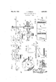
ig. l is aside elevation showiiigthe arrangem'ent ofa'stripiieed e uipped with the fimproved'registering device;
Flgsi2fand 2a are'ifsectio'nal details' in enis providedineans for intermittently; advancinga strip of wrapping materialhaving a plurality of printed or.'"embossed portions, meansyfor retracting thestrip, means for cutting the strip; and means for frictionally engaging the printed .or embossed surface of one of said portions for stoppingthe re tracting" movement of the strip to bring "it into'predetermined position relative to said cludesadriven feed roller; an "idle'feed roll- 7 er, andcam means for'pressing-the idle feed;
tently feed thestrip. In the preferred'form ofconstruCtiOn', the means for retracting the Istripfincludesf a yieldingly mounted arm arranged to engage a portion ofthe stripto dis place it with respect to thefstrip; whereby to retract the strip, and a jbrake firi'gerfor frictionally engaging thei printed or embossed-portion oflthe strip tovstojpthe re tracting movement thereof These various means and parts may be widely varied in construction within (the scope of the claims, for the particular *deviee selectedxto illus trate. the; invention is but" one [of many possible embodiments, ofthe same The inven- 15 tion; therefore is not'to bejrestrictedto' the" 1 been stopped for a suflicient length olftime ermit the above described action of'the registering device and the subsequent cutting of the strip, is automaticallyresumed by the specific construction shownanddescribed V The wrapper web or stripWfwhich has an which also mayh ave 'markingl'ifl M planted or-embossed betweenlabel'a'i f respectively. Shaft Qis'statiOnarily held by a timed intermittent motionfimparted to it from thePdrive of the -machine and shaft 10 7' j S-looselymounted in onecarmief the bell cutting'means. the best const'ructions con- 7 templat'ed, the strip advancing means in;
the frame of the packagingmachineand has a V I i 0.1 7 labels L 'printedon 1 it at' regular intervals i 13 held in engagementwith a cam 1 L on shaft 15 by a spring 16. The cam shaft 15 is inter connected in timed relation with the drive of the packaging machine, making one revo- I I Fig. 2a. After suflicient time has elapsed for and 3?, .1
lution for. each cycle of themachine.
s The" strip 'ibetween arollers a' 6 passes over a roller 17 held in juxtaposition with a suitablerstrip guide 18 which has a' lrece'ss adjacent the; strip, andover a'zbrake finger19 bearing iagainst'fai. support 2031.1 The: roller 17 is carried by an arm 21 pivoted on I stud 22 and held in tension a'gaii1st-th'e=strip* by a spring 23 whichtends to move the arm 21 upwardly butis quite weak so as-to peri mit thearms to beidepressed, the estrip when in tension. during :the operation of the "feedrollersfi -v The zuplwardsmotionof arm; 21 which pushes: a portion of the "strip I into the recess in the strip guide,.when not "otherwise stopped, ;is.-1imited by stop 2% -':lh e =finger-19 which pivoted ona stud-25 v has a fiat end surfaceewitha sharp edge-and =is.-tensioned.by-aspring26 which holds the r; .fingerl against a stop-2'1 while its fiat end (.surfaceigently pressesthe stripwhich at this ,Lspointais vbearing.againsttheadjustable sup f port 20;: The spring .26,is,-so adjusted that i the. finger 19 bears against stop 27. only when v u a-nyunprintedi portion of the; stripfvW "passes ,over thefinger, but ,is:lifted "off the stop by i ,the strip ,-WhGI1; afiprintedsportionr thereof The strip I I ,m-achine, is intermittentlyea'd vanced:throughthe feedrrollers i' and 8-by a length-somethe stripcfeed is stopped turningithe arm 11 I: feed itensionof .thegstrip 'Tahe latter there i upon, loses its potwer to, depress the arm 21 which is thusenabledto. push .out1'o f aligniwment the portioniof the strip limited by the v Q \L guide 18,- therebyaetractin'g. the strip to take up the ,excessively :advanced length, the rey tracting movement of the web being stopped :by the: friction ofithe printing of onegof the labels-L as the latter." passes backwards; over a fingerl9, therebyFjJammin-ggthe-printedpor- Y 'tion of the web-between the-fingerall) and qsupport 20,:as shown in Fig; 2. .aln -ithe case of; separate ma rkingvrlines; M, the take-np 1 I Whatiscl aimedisi II .Y, a :1. lnastriprregistering device, theicombi reel shaft-5ihas abrakefwheel 36 en-' I I I I I I II natlonwith means fore-intermittentlyadvancgaging with a shoer 3-7 J i VOtedon-shaft 38- a and held against wh'eel 36 r-byethe tension of I I I I I I I I v equally spaced printedhoroembossedlportions,
' crank lever 11 on shaft 12 whichhas a roller motion of the web is stopped by the thickness of the mark'registering with the contact edge of finger 19 which by the rearward motion of the web is jammed tightly against the unmarked portion of the latter, as shown in this rearward movement and its stopping to take place, the cam 14 releases arm 11, per- "initting the spring 16 to pull feed roller 8 into engagement with rollerfljwhichtat that time isat'rest,swhereup.on the knife 28 is ac-v tuated by cam 35. The web .VV having been stopped by the engagement of finger 19 with the printing of one of the labels L, or with "the edge of one of the spaced. marks M, the
cuts made by-i the knife .28 are valways v at the same distance from thejlabels and :the latter thereforejcan be made to 'o c'cupyany desired" position .on', the finished. package by suitably: spacing the" knife l28-1from the. edge qof finger 19. r i Y 'L When the I labels "cu p y: only a comparativplyyismallf portion of L. are 'sonarrow as to 00- ;the width .of the strip and particularly minfcase of 'very thin wrapping materialiwhere the thickness? the A printing relatively large; difficultygmay be encountered in rollvingjuzp ,the: wrappin'ggweb .as then the printed I portion. [of the width. Willgbulg and thus .forina reel of. curved-or unevenisurfabe. 11i
this case, it will be eiipe'dient to print or em- I boss raised .marks,M.ial l the 'way acr oss the. passes over the same inlthef -orivarddirections width fl i i ebyi S i l F g-' z The came; knife 28, which at timedlinte'r- I ,35 "vals cuts'sections 'ofthe strip. YV- along the 1 ledgeriplate 29, iscazrried by apivoted-bar swung-bye rod31aactnatedby a GaIH-lGVQP :9 f v32 sfulorumed on shaft vi-lxii' andi having roller, 1 H 4:34 in engagement with a cam35on cam. shaft 11-0 '4 The by securing 'anleven; supportof the web} over a its entire widthbetween therlprinted ,J's'pojts,
These "niarks may.then,bel made use of to" register ,theiweb; in: t he manne11explained above. "4' a ing a jstripofimaterialhaving a plurality of 1 only of onefofs'aid' portions for stopping the retracting movement of; the strip toflbring the leading printed or embfosse'd portioninto predetermined position relative to, said .e u tting means: said 'yieldable' means yielding to permit passage of the printed or embossed per 4. tions of the strip :under} the answer; said strip advancing means;
' In a str p reg1ster1rig device tlie; combination with meansfor intermittently advancing a strip of materialchaving a plural'iityeef equally spacedprint'ed 'oremboss'ed iportions,
of'mechanism.forretracting .thestrip, means 1 for subsequently, cutting the strip.lto;.-sever the leading printed or embossed ,portion therefrom; and; y-i-eldableg meansfifo -rz frictionally engaging the vprinted or embossed surface only of one of said portionsfor stopping the retracting movement of the strip to bring the leading printed or embossed portion into predetermined position relative to said cut-i ting means, said yieldable means yielding to permit passage of theprinted or embossed portions of the strip under the tension of said strip advancing means, saidadvancing means including a V positively driven feed roller above said strip, a lever below said strip, a feed roller loosely mountedon said lever, and cam means for actuating said lever to press said strip between said. rollers, whereby to intermittently advance said strip.
3. In a strip-registering device, the combination with means for intermittently advanc-' ing a strip of material having a plurality of equally spaced printed orembossed portions, of mechanism forretracting the strip, means for subsequently cutting the strip to sever the leading printed or embossed portion therefrom, and yieldable means for frictionally engaging the printed or embossed surface, only of one of said portions for stopping the retracting movement of the strip tobring the leading printed or embossed portion int-o predetermined'position relative to said cutting means, said yieldable means yielding to permit passage of the printedor embossed portions of the strip under'the tension of said strip advancing means, said mechanism including a strip guide arranged above said strip and provided with a recess adjacent said strip, a pivoted arm arranged below said strip, a roller looselymou'nted on said arm therefrom, and means for rrictionally engag-r ing the printed orembossed surface of one of said portions for stopping the retracting movement of'the strip to bring the leading printed or embossedportion into predetermined position relative to said cutting means, said means for frictionally engaging said strip including a brake finger arranged ad:
'jacent the printed or embossed surface of' having a plurality of equally spaced, printed or embossed portions of greater total thick ness than that of the unprinted or unembossed'portion of-the strip, of means for subsequently cutting'the strip to sever thesame between printed portions,' and elements on opposite sides of the strip having opposed strip engaging surfacesspaced apart'a distance greaterthan the thickness of the strip alone, but less than the thickness of the strip plus the additional thickness of the print or of said elements to release the strip when it 7 v is advanced and catch on the printed or em: bos sed 'portion when it'is retracted;
A 6; In a strip registering device, the 'combi nation with means for intermittently advancinga strip of material having a plurality of f of means for subsequently;cutting-rthestrip, i
to sever the same between printed portions, and elements onflopposite sides'ofgthe strip ness of the. strip "alone, but less than the thickness of the strip plus thefadditional thickness of, the print or embossing lto stop the' strip in predetermined 1 positions, means mounting one of said elements for retracting movement'to release the strip,"one of said elements: having an abutment adjacent 'its strip engaging surface, said means "support-v ing said last mentioned element at an acute angle to the length ofthe strip to permit movement of printed or embossed portions past the abutment when moved in one direc tion while causing the same to catch on the embossed or printed portion when moved in the opposite direction, and mechanism for slightly overfeeding the strip in the onedireca tion and then retracting it in said opposite direction.'
name to this specification.
LESTE ERENOI-Q said strip, and a spring urging said finger 1 toward said strip, and a stop holdingsaid finger in position to engage only the printed or embossed portions of the strip, whereby to stop the retracting movement ofsaid strip 'whensaid finger engages the printing or embossing thereon.
5. In a strip registering device, combination with means for intermittentlyadvance 1 I .ing and then retracting a strip of material 9o 7 having opposed strip engaging surfaces g spaced apart a distancegreaterthanthethick- Y r 112, In testimony whereof, Ihave signed my 7
Priority Applications (1)
| Application Number | Priority Date | Filing Date | Title |
|---|---|---|---|
| US507235A US1859962A (en) | 1931-01-07 | 1931-01-07 | Strip registering device |
Applications Claiming Priority (1)
| Application Number | Priority Date | Filing Date | Title |
|---|---|---|---|
| US507235A US1859962A (en) | 1931-01-07 | 1931-01-07 | Strip registering device |
Publications (1)
| Publication Number | Publication Date |
|---|---|
| US1859962A true US1859962A (en) | 1932-05-24 |
Family
ID=24017798
Family Applications (1)
| Application Number | Title | Priority Date | Filing Date |
|---|---|---|---|
| US507235A Expired - Lifetime US1859962A (en) | 1931-01-07 | 1931-01-07 | Strip registering device |
Country Status (1)
| Country | Link |
|---|---|
| US (1) | US1859962A (en) |
Cited By (15)
| Publication number | Priority date | Publication date | Assignee | Title |
|---|---|---|---|---|
| DE743434C (en) * | 1940-05-25 | 1943-12-24 | Efka Werk Fritz Kiehn | Method and device for producing cigar cell bags |
| US2636731A (en) * | 1948-03-30 | 1953-04-28 | Pneumatic Scale Corp | Web feeding means for container forming apparatus |
| US2709587A (en) * | 1952-04-29 | 1955-05-31 | Markem Machine Co | Means for intermittently feeding strip material |
| US2824736A (en) * | 1955-04-21 | 1958-02-25 | Hobart Mfg Co | Ticket printer |
| US2846006A (en) * | 1955-04-21 | 1958-08-05 | Waldes Kohinoor Inc | Cutting slide fasteners to length |
| US2848224A (en) * | 1947-07-01 | 1958-08-19 | American Mach & Foundry | Registration device for wrapping machines |
| US3053150A (en) * | 1957-03-11 | 1962-09-11 | Hudson Pulp & Paper Corp | Apparatus for making paper bags |
| US3183751A (en) * | 1960-10-05 | 1965-05-18 | Dunlop Rubber Co | Apparatus for cutting lengths of rubber or rubber-like material from strips or sheets |
| US3583616A (en) * | 1969-07-29 | 1971-06-08 | American Can Co | Web registration device |
| US3776441A (en) * | 1972-05-10 | 1973-12-04 | Forthmann Label Services Co | Strip material feeding device |
| US4422357A (en) * | 1979-10-15 | 1983-12-27 | Larsen Mogens D | Apparatus for advancing a predetermined length of strip-shaped material |
| US4557169A (en) * | 1982-07-08 | 1985-12-10 | Kabushiki Kaisha Sato | Continuous tag cutting/feeding apparatus |
| US4779781A (en) * | 1983-02-10 | 1988-10-25 | Ab Tetra Pak | Method and an arrangement for the feeding of a material web |
| US5150022A (en) * | 1991-03-05 | 1992-09-22 | Waddington Electronics, Inc. | Press feeder and pilot release using servo control |
| US5937717A (en) * | 1995-08-18 | 1999-08-17 | Iino; Mitsunobu | Device for feeding and discharging a work in an automatic hollow-pipe cutting apparatus |
-
1931
- 1931-01-07 US US507235A patent/US1859962A/en not_active Expired - Lifetime
Cited By (15)
| Publication number | Priority date | Publication date | Assignee | Title |
|---|---|---|---|---|
| DE743434C (en) * | 1940-05-25 | 1943-12-24 | Efka Werk Fritz Kiehn | Method and device for producing cigar cell bags |
| US2848224A (en) * | 1947-07-01 | 1958-08-19 | American Mach & Foundry | Registration device for wrapping machines |
| US2636731A (en) * | 1948-03-30 | 1953-04-28 | Pneumatic Scale Corp | Web feeding means for container forming apparatus |
| US2709587A (en) * | 1952-04-29 | 1955-05-31 | Markem Machine Co | Means for intermittently feeding strip material |
| US2824736A (en) * | 1955-04-21 | 1958-02-25 | Hobart Mfg Co | Ticket printer |
| US2846006A (en) * | 1955-04-21 | 1958-08-05 | Waldes Kohinoor Inc | Cutting slide fasteners to length |
| US3053150A (en) * | 1957-03-11 | 1962-09-11 | Hudson Pulp & Paper Corp | Apparatus for making paper bags |
| US3183751A (en) * | 1960-10-05 | 1965-05-18 | Dunlop Rubber Co | Apparatus for cutting lengths of rubber or rubber-like material from strips or sheets |
| US3583616A (en) * | 1969-07-29 | 1971-06-08 | American Can Co | Web registration device |
| US3776441A (en) * | 1972-05-10 | 1973-12-04 | Forthmann Label Services Co | Strip material feeding device |
| US4422357A (en) * | 1979-10-15 | 1983-12-27 | Larsen Mogens D | Apparatus for advancing a predetermined length of strip-shaped material |
| US4557169A (en) * | 1982-07-08 | 1985-12-10 | Kabushiki Kaisha Sato | Continuous tag cutting/feeding apparatus |
| US4779781A (en) * | 1983-02-10 | 1988-10-25 | Ab Tetra Pak | Method and an arrangement for the feeding of a material web |
| US5150022A (en) * | 1991-03-05 | 1992-09-22 | Waddington Electronics, Inc. | Press feeder and pilot release using servo control |
| US5937717A (en) * | 1995-08-18 | 1999-08-17 | Iino; Mitsunobu | Device for feeding and discharging a work in an automatic hollow-pipe cutting apparatus |
Similar Documents
| Publication | Publication Date | Title |
|---|---|---|
| US1859962A (en) | Strip registering device | |
| US2776068A (en) | Tape applying movement | |
| US3628408A (en) | Stamp dispenser | |
| DE1511873C3 (en) | Device for dispensing labels | |
| US3435717A (en) | Label feed and cutting means | |
| US2518011A (en) | Label feeding mechanism | |
| US2721612A (en) | Machine for feeding flimsy web material | |
| US2482711A (en) | End-labeling attachment | |
| US3065691A (en) | Printing and die cutting machine | |
| US1908291A (en) | Machine for assembling strip sections and box-blanks | |
| US2366971A (en) | Dispenser for tacky tape | |
| US3147673A (en) | Apparatus for attaching handles to paper bags | |
| US1543434A (en) | Card-forming machine | |
| US2569101A (en) | Label severing and applying machine | |
| DE2217032B2 (en) | Equipment placing parts cut off continuously from running band - has periodically nonuniform drive for speeding up and slowing down transferred parts to object | |
| US3158522A (en) | Configured web-cutting apparatus | |
| US2614523A (en) | Gummed tape serving and moistening mechanism | |
| US2194309A (en) | Gummed tape | |
| US3687347A (en) | Quick change labeling head | |
| US2880656A (en) | Window envelope machine | |
| US2164935A (en) | Method and apparatus for forming parcel handles | |
| US1927585A (en) | Paper feeding mechanism | |
| US2816408A (en) | Bottom wrapper feeder | |
| US3303758A (en) | Tear tape applying mechanisms for wrapping machines | |
| US2365757A (en) | Web registering device |