US1859959A - Machine for inserting eyelets in window shades and the like - Google Patents
Machine for inserting eyelets in window shades and the like Download PDFInfo
- Publication number
- US1859959A US1859959A US483416A US48341630A US1859959A US 1859959 A US1859959 A US 1859959A US 483416 A US483416 A US 483416A US 48341630 A US48341630 A US 48341630A US 1859959 A US1859959 A US 1859959A
- Authority
- US
- United States
- Prior art keywords
- drill
- eyelet
- hole
- machine
- clutch
- Prior art date
- Legal status (The legal status is an assumption and is not a legal conclusion. Google has not performed a legal analysis and makes no representation as to the accuracy of the status listed.)
- Expired - Lifetime
Links
- 238000005553 drilling Methods 0.000 description 9
- 238000010276 construction Methods 0.000 description 2
- 238000003780 insertion Methods 0.000 description 2
- 230000037431 insertion Effects 0.000 description 2
- 101150078000 arid3a gene Proteins 0.000 description 1
- 238000012937 correction Methods 0.000 description 1
- 230000008878 coupling Effects 0.000 description 1
- 238000010168 coupling process Methods 0.000 description 1
- 238000005859 coupling reaction Methods 0.000 description 1
- 230000000994 depressogenic effect Effects 0.000 description 1
- 238000007599 discharging Methods 0.000 description 1
- 238000004519 manufacturing process Methods 0.000 description 1
- 239000002184 metal Substances 0.000 description 1
- 229920000136 polysorbate Polymers 0.000 description 1
Images


Classifications
-
- A—HUMAN NECESSITIES
- A43—FOOTWEAR
- A43D—MACHINES, TOOLS, EQUIPMENT OR METHODS FOR MANUFACTURING OR REPAIRING FOOTWEAR
- A43D100/00—Setting or removing eyelets, buttons, lacing-hooks, or elastic gussets in shoes
- A43D100/02—Punching and eyelet-setting machines or tools
-
- Y—GENERAL TAGGING OF NEW TECHNOLOGICAL DEVELOPMENTS; GENERAL TAGGING OF CROSS-SECTIONAL TECHNOLOGIES SPANNING OVER SEVERAL SECTIONS OF THE IPC; TECHNICAL SUBJECTS COVERED BY FORMER USPC CROSS-REFERENCE ART COLLECTIONS [XRACs] AND DIGESTS
- Y10—TECHNICAL SUBJECTS COVERED BY FORMER USPC
- Y10T—TECHNICAL SUBJECTS COVERED BY FORMER US CLASSIFICATION
- Y10T29/00—Metal working
- Y10T29/51—Plural diverse manufacturing apparatus including means for metal shaping or assembling
- Y10T29/5104—Type of machine
- Y10T29/5105—Drill press
- Y10T29/5107—Drilling and other
Definitions
- Fig. 2 is-a section'substantially on the line -2-2Fig. 1.
- e V Fig. 3 is a fragmentary sectional view illustrating the means for Withdrawingthe let therefrom.
- i i v Fig. 4 is an enlarged sectional view show ingth e op'eration of settingthe eyelet.
- 7 Fig. 5 is-a fragmentary sectional view of the end of the curtain :showing the eyelet therein a i Fig. 6 shows eyelet-delivery chute for. discharging an eye.-
- Fig 7 is a fragmentary sectionalviewshow-' ing the clutch mechanism for driving-the dril1; w, Fig. 8 is a similar View showing the way in which the clutch is disengaged while the eyelet isbeingseh V f Fig. 9 is a fragmentaryview partly broken outshowing, the positioning gauge for the curtain
- the invention includes a combined drilling F is an enlarged section tn the line 10 10 Fig. 9..
- Fig. 5 lindicates. suchlan eyelet, it having the usual head 5-atone end Fig. 5, 1 indicates awin:
- a drill member 12 which is adapted to drill the hole throughthe stick 3 and a setting I member 13 mounted on the stem of the drill and adaptedto co-operate with an anvil meme ber 14 carried by the bed 8 forsetting the eyelet.
- the anvil member 14 is made hollow or tubular to permit the drill to pass therethrough as the eyelet'is' being-set. 4 x
- the setting member 13 is loosely mounted on the spindle of the drill and a suitable ball 7 bearing 15 is provided for said member.
- Means are also provided for unclutching the drill shaft from its driving means while the eyelet is being set so that at this time the drill will not berotating.
- the drill spindle 10 may be given its rotary and'vertieal movement in any approved way. As herein shown it is op-erated from adr-ive shaft 16 which is mounted in bearings on the frame and is driven from any suitable source of power. This shaft has a belt pulley 17 thereon over which runs a belt 18 for rotat- I ing'the drill spindle. This belt passes over I, two direction pulleys 19 and around .a' pulley at 71.- r
- the drill spindle 11 extends through the sleeve 7 0 and'is adapted to be clutched there'- to bya suitable clutch indicated generally 21 indicates anotherdirection pulley engaging one run of the belt and operating to maintain said run in proper alignment with one of the pulleys 1'9.
- acam member-22 which is mounted on stud'or shaft -23carried by the frame, saldcam member having a cam groove 24 in which is received a follower 25 carried by a lever 26, said lever being pivotally mounted at 27 and havingat its free end a forked portion 28 which embraces the spin- 3 dle 10 and is received between two'collars 29 i on the spindle.
- the cam 22 derives its-rotation fro'm't'he shaft 16 andmeans areprovided whereby the operative connectionbev tween the shaft 1-6 and the cam 22 willbe dis-' rupted after each complete excursion of the drill spindle.
- the shaft 16 has a pinion 30' fast thereto which meshes witha-large gear 31 whichis fast on the hub of a ratchet member 32which in turn is keyed to the shaft 23
- the cam member '22 has pivoted thereto at'34 a pawl member 33 which is adapted to co-operate with the ratchet teeth 36fori-ned'on the ratchet member 32. Said pawl is acted on by a spring which tends to throw it into engagement with said ratchet teeth and when said pawl is in engagement with the ratchet teeth the gear '31 willbe coupled to the cam.
- pin 37 which is slidably mounted in the frame and which, when in its operative position, w ll engage the under face 38 of the rear end of the pawl as the cam is rotated thereby to swing said pawl out of engagement with the.
- The'pin 3.7 may be controlledmanually in any approved way. As'herei'n shown the said pin 1s provided at one end with a head 40' adapted to be engaged by a latch 41 p'ivotal- 7 1y mounted at 42' to an elbow-lever 43;, the latter being pivoted to theframe at 44* The arm 45 of the elbow-lever is 'connected'to a suitable treadle or other control adapted to be manually operated.”
- the pawl will then 'beswung into operative engagement with the ratchet teeth-36 by the spring 35 as above descrihedso. that the ro- 'tation of the gear 31 will be communicated and having at one end a head 49that engages a! collar 5O'on the pin 37.
- the sliding-pin 47 has the collar 51 at one end against w ich the spring 46 bears. When the pin 37 moves to the left as above described the engagement ofthe collar with the head 49 moves. the pin 47to the left thereby compressing the spring 46.
- Meansare provided for; disengaging the latch 41 from the head 40 as soon as the pin 37 has been entirely withdrawn from the latch 33's0 that the compressed spring 46 will function to restore the pin 37 to its normal position.
- the latch 41 is :acted on by a spring 52 which-normally holds it, in position against the'head 40.
- the elbow lever 43 carries a knocleoff screw 93 which is adapted to en gage a pin 94 carried by the latch 41 when The the arm 43 swings to the left-L
- the continued swinging movement of the arm 43 to the left after the knock-off screw 93 engages the pin 94 will cause the latch 41 to swing downwardly snfliciently to be released from the head 40 thereby allowing the spring 46 to return the pin 37 to its normal position.
- the eyelets 4- are delivered to the drill through a raceway 53 which extends from a magazine 54.
- a yieldable stop situated'to engage the bottom eyelet and yieldingly. retain the same in position directly underneath the the eyelet the latter will be drill.
- the yielding stop 55 which is inthe nature of a spring finger, will yield to permit the eyelet to pass out ofthe; raceway during the backwardmoyement of the latter. As the eyelet is withdrawn from the raceway the drill continues its downward movement thereby drilling the hole in the stick, during.
- the raceway is rigid with the magazine 54- and the latter is pivotally mounted on the frame as shown at 56.
- the magazine has which is in the nature of a cam face adapted to be engaged by a projection 59 formed on. the lever 26 when the latter swingsdownwardly.
- V the frame and which limits the gravitating movement of-the. magazine and raceway and brings them to rest with the end eyelet properly aligned with the drill.
- The-magazine v may-beprovided with any suitable means for. fillingthe racewayiwitheyelets.
- the magazine has located within it a rotarybrush 63 and the walls of themagazine are formed near the bottom .thereofwith openings 62' .which lead 6 to a passageway -170jtl'1at extends around themagazine and communicateswith the'upperend of the raceway.
- Thebrush 63 is carried by a shaft extends through thebottom of the magazine and'which has at its end agear 65 :meshing with a gear66 mounted on theshaft23JLaThe rotation of the shaft 23 thus rotates the brush andtprovides. forsfilling' the racewayf with eyelets. j j .7
- the pinion 66 is splined-on theIend of the shaft 23 soqthat it can be-movedinto and'out of engagement Withthe gear 65:.
- the movement of thep mon lIltOltS 'operatlve'and '1noperative positions is governed 'by-aforked adapted to be actuated'by an arm 681(1Ifit is found that the raceway is filling up: with eyelets faster th an'they'are being used *the pinion 66 can be disconnectedffrom the gear "65 for an interval to 'allowthe accumulated eyelets to be used.
- the machine herein disclosed is accomplished by adjusting the pivot'of the lever 26. :This lever is pivotallymountis: provided.
- the pin 27 iseccentric with reference tothe axis of the sleeve 171. Therefore, by turning the sleeve about "the stud w 172 the pivotal point-of) the leverj26 may be shifted with reference to the cam thereby varying the posit-ion of the drill and also its amplitude of movement.
- the machine herein illustrated is also it vided with means for disconnecting the clutch 71 automatically after the hole has been drilledand just prior' tothe setting of the eyeletso that during the settingoperal- -tion the drill will'notbe rotating.
- 'Th e clutch :71 comprises the two clutch elements 72 and 73, the clutch element 72 being fast on the constantly-rotating sleeve 70.
- the clutch element 73 is'splined to the shaft 170 through a key 74 operating in a groove75 formed in the shaft, whereby said clutch element can move longitudinally of the shaft but is fast to the shaft so far as rotative .niovement is concerned.
- the clutch member 73 is normally held in engagement with the clutch member 72 by means of 'a spring 175 :which encircles the drill shaft ;10 i and one end of which engages the collar 29 and the other of which; engages the clutch member 73.' 7 n IThe-spindlelO is provided with a clutchdisengaging projection 76 which is located Duringthe drilling operation the "clutch members 72, 73 are in clutching engagement "so that the drill shaftwill.
- the machine herein illustrated also includes a suitable gauge member for properly positioning the curtain so as to ensure that the eyelet will always be placed in the central portion thereof;
- the bed 8 is shown as being cutaway along one edge as indicated at 77 to form a restor seat for av au e bar 78'.
- This bar has a general channel shape and it l secured to it two runners or slides 79 and 8O which aremovable longitudinally of the bar '8 and which carry positioning fingers 81 and 82 respectively.
- a, V a "While the hole is being drilled and theeyelet is being set in the stick 3said-stick will be heldbetwcen thetwo gauge fingers 81,- 82
- the runners orslides 79 are connected together so that they. move in unison but in opposite directions and hence'if one slide is adjusted toward and from the center the other side will be correspondingly adjusted and thus in any adjusted position the stick will always be properly centered by the fingers.
- the gauge memher'78 is in the form of a i channel member and in the space between the legs thereof is located two pulleys 83 around which extends a cord or flexible connection 8 .
- One side of this connection is connected to the slide 80 asshown at 85 and the other side'of the flexible connection is connected to the slide79 as shown a 86.
- Each slide is made of sheet metal and is formed with the depending flanges 87 which embrace the edges of the member 78 and is also formed with the inturnedflanges 88underlying the member 78.
- One of the flanges 88 of the slide 80 has a block 85 secured thereto to which both ends of :the flexible connection or cord 84: are
- the combination with a drill of means to give the drill a forward feeding movement, and means operative forward feeding movement of the drill to introduce an eyelet into the drilled hole and set said eye-let.
- combination with adrill spindle, of a drill mounted thereon means to support an eyelet in position to be penetrated by the drill during its feeding movement, and me ans carried on the drill spindle to introduce the eyelet into-the drill hole.
- an eyelet-setting member carried by the drill and operative during thekfeeding movement of the latter to introducethe eyelet into the drill hole, and means cooperating with said setting member to set the eyelet;
- the combination with a drill spindle, of a drill carried thereby means to rotate the spindle, means to give the drill its feeding movement, means to deliver anieyelet to the drill at each operation thereof, and means to introduce the eyelet into the drill hole and set the veyelet during the feedin movement of the drill.
- the combination with a drill spindle, of a drill carriedthereby, means to rotate the spindle, means to give the drill a feeding movement,
- an eyelet magazine a raceway connected thereto to which eyelets are delivered there ⁇ from, said raceway normally presenting the end eyelet therein in position to be penetrated by the drill during its feeding movement, means actuated by the drill-feeding means to retract the raceway after the eyelet therein has been penetrated by the drill thereby to discharge the eyelet fromthe raceway, and means associated with the drill to introduce V the eyelet to the drilled hole and to set the eyelet.
- a combined drill andeyelet-setting machine the combination with a drill for drilling an eyelet hole, of means including a clutch for operating said drill, meansassoa into said hole and set. said eyelet, andlmeans for disconnecting the clutch after the hole hasbeen drilled and whiletheeyeletis being set.
- V 1 12 Ina combined drill and eyelet-setting machine, the combination with a drill, of means to give the drill a feeding movement,
- means including a clutch, for rotating" the drill, means operative during the feeding movement of the drillto introducean eyelet into the drilled hole and set said eyelet and meansactuated by said feedingmovement to disengage the clutch while the'eyele't is being set.
- the V combination with a-drill spindle, of'a drill carried'thereby means to give tothe drill spindle a feeding movement, means carried by the drill spindle to introduce an eyeletlinto the drilled hole, means co-operating with said drill toset said eyelet, and means actu ated by the feeding movement of the drill spindle to disengage said clutch while the eyelet is being set.
Landscapes
- Drilling And Boring (AREA)
Description
y ,1 I c. N. COLPITTS 1,859,959
MACHINE FOR INSERTING EYELETS IN WINDOW SHADES AND THE LIKE Filed Sept. 22, 1930 S'Sheets-Sheet l 2 lnvenTor.
y 24, c. N. COLPITTS 1,859,959
MACHINE FOR INSERTING EYELETS IN WINDOW SHADES AND THE LIKE Filed Sept. 22, 1930 5 Sheets-Sheet 2 Fig. 2.
8 I l 1 64 as l l F 25 Q 7 63 I 54 22 7 "asa 52 4a 47 3 24 Y 46 5\ 32 O 4\ so as \nvenTor. Ccflvin Colpifis b /MMkM MT ys.
y 24, 1932- c. N. COLPITTS 1,859,959
MACHINE FOR INSERTING EYELETS IN WINDOW SHADES AND THE LIKE Filed Sept. 22, 1950 5 Sheets-Sheet 5 May 24, 1932. c. N. COLPITTS MACHINE FOR INSERTING EYELETS IN WINDOW SHADES AND THE LIKE Filed Sept; 22, 1930 5 Sheets-Sheet '4 May 24, 1932. c, COLPITTS I 4 1,859,959
MACHINE FOR INSERTING EYELETS IN WINDOW SHADES AND THE LIKE 'Filed Sept. 22, 1930 5 Sheets-Sheet 5 Patented May 24, 1932 UNITED S A ES- P CALVIN n. oorrirtrs; QFMALDEN, MAssAo'HusE T'rs; nssrenon ro I-41mm win ;.now snann memnn COMPANY, or BOSTON, MASSACHUSETTS,' A CORBQRATION or ivmssacnnsnrrs M'Ao imn Foe Insnnkrme EYELETS IN wrnno'w SHADES AND TI-I'EFLIVKEY Application filed September 22, 1930. Serial No. 482,416.
'In' the manufacture of window shades it is customary to place a wooden stick in the hem at the lower end of the shade and then to insert a grommet or eyeletthrough the stick in order to provide for attaching thepull cord to the curtain. The insertion of the grommet or eyelet involvesthe operation of drilling a hole through-the woodenstick and then the insertion and settingof the eyelet.
It is the object of my present invention to provide a novel machine bywhich'the drillA ing of the hole and'the setting or" the eyelet are accomplished by the'same mechanism and i nsertion'of an eyelet of thissort necessitates at the same time. 1'5
and eyelet-setting tool which operates during its initial operative movement to drill the hole for the eyelet and during its final operative movement to set the-eyelet. In order '20 to give an understanding of myinvention, I
have ii lustrated herein a selected embodiment.
thereof which will now be described, after which the novel features will be ointedout in the appended claims."
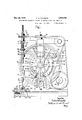
:Inthe drawings: T .1 -1 Fig. l'is a side'view of a combined drill and eyelet setting machine embodying myin vention. 7
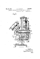
. Fig. 2 is-a section'substantially on the line -2-2Fig. 1. e V Fig. 3 is a fragmentary sectional view illustrating the means for Withdrawingthe let therefrom. i i v Fig. 4 is an enlarged sectional view show ingth e op'eration of settingthe eyelet. 7 Fig. 5 is-a fragmentary sectional view of the end of the curtain :showing the eyelet therein a i Fig. 6 shows eyelet-delivery chute for. discharging an eye.-
the completed curtain;
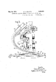
' Fig 7 is a fragmentary sectionalviewshow-' ing the clutch mechanism for driving-the dril1; w, Fig. 8 is a similar View showing the way in which the clutch is disengaged while the eyelet isbeingseh V f Fig. 9 is a fragmentaryview partly broken outshowing, the positioning gauge for the curtain The invention includes a combined drilling F is an enlarged section tn the line 10 10 Fig. 9..
' Referring first to dow shade of ordinary construction whichis provided at its lower end with the usual hem 2 in which is i'nserted the Wooden stick 8. As stated above it is common practice toinsert an eyelet-through the stick 3 in order to provide an opening to which a pull cord may be secured. In Fig. 5, lindicates. suchlan eyelet, it having the usual head 5-atone end Fig. 5, 1 indicates awin:
and being 'clinchedoveras. shownat 6 'at the other end thereby locking'it in place. The
first drilling a hole through the stick 3,-.and 5 as stated above the present invention has for.
its-object to provide a novel machine which will at one operation drill the hole for the eyelet and set the eyelet.
The machine-comprises a; suitable frame 'r' having-abase or work support 8 on which the endrof the curtain, is. supported. The
drilling of the'hole for the eyelet and the" "setting of; the eyeletis accomplished by a combined drill and eyeletrsettingtoolS) which is mountedon a rotary spindle 10Hthat is slidable vertically in suitable bearings ll and carried by the frame. This toolcomprises,
a drill member 12 which is adapted to drill the hole throughthe stick 3 and a setting I member 13 mounted on the stem of the drill and adaptedto co-operate with an anvil meme ber 14 carried by the bed 8 forsetting the eyelet.
i In the operation of the machine, whenthe drill is lowered into operative position to drill the hole, it will pass through an eyelet which is properly positionedtoreceive the drilland as the drill.proceeds theeyelet slides upthe and thew-operation of the setting'member 13 a and the anvil member 14 serves to set theeye f drill until it engages the settingmembjer 13. I
let by clinching over the lower end thereof as shown at 6 in Fig. 5. v The anvil member 14 is made hollow or tubular to permit the drill to pass therethrough as the eyelet'is' being-set. 4 x
The setting member 13 is loosely mounted on the spindle of the drill and a suitable ball 7 bearing 15 is provided for said member.
Means are also provided for unclutching the drill shaft from its driving means while the eyelet is being set so that at this time the drill will not berotating.
' The drill spindle 10 may be given its rotary and'vertieal movement in any approved way. As herein shown it is op-erated from adr-ive shaft 16 which is mounted in bearings on the frame and is driven from any suitable source of power. This shaft has a belt pulley 17 thereon over which runs a belt 18 for rotat- I ing'the drill spindle. This belt passes over I, two direction pulleys 19 and around .a' pulley at 71.- r
20 which is made fast to a sleeveTOthat :is journalled in the upper bearing member 11. The drill spindle 11 extends through the sleeve 7 0 and'is adapted to be clutched there'- to bya suitable clutch indicated generally 21 indicates anotherdirection pulley engaging one run of the belt and operating to maintain said run in proper alignment with one of the pulleys 1'9. r
for giving the spindle 10 its vertical movement I have providedacam member-22 which is mounted on stud'or shaft -23carried by the frame, saldcam member having a cam groove 24 in which is received a follower 25 carried by a lever 26, said lever being pivotally mounted at 27 and havingat its free end a forked portion 28 which embraces the spin- 3 dle 10 and is received between two'collars 29 i on the spindle. The cam 22 derives its-rotation fro'm't'he shaft 16 andmeans areprovided whereby the operative connectionbev tween the shaft 1-6 and the cam 22 willbe dis-' rupted after each complete excursion of the drill spindle. The shaft 16 has a pinion 30' fast thereto which meshes witha-large gear 31 whichis fast on the hub of a ratchet member 32which in turn is keyed to the shaft 23 The cam member '22 has pivoted thereto at'34 a pawl member 33 which is adapted to co-operate with the ratchet teeth 36fori-ned'on the ratchet member 32. Said pawl is acted on by a spring which tends to throw it into engagement with said ratchet teeth and when said pawl is in engagement with the ratchet teeth the gear '31 willbe coupled to the cam.
, pin 37which is slidably mounted in the frame and which, when in its operative position, w ll engage the under face 38 of the rear end of the pawl as the cam is rotated thereby to swing said pawl out of engagement with the.
as soon as this occurs, the spring 35 acts to I swing the pawl into operative engagement with the ratchet teeth 36 thereby coupling the gear 31 to the cam 22. 1 V v The'pin 3.7 may be controlledmanually in any approved way. As'herei'n shown the said pin 1s provided at one end with a head 40' adapted to be engaged by a latch 41 p'ivotal- 7 1y mounted at 42' to an elbow-lever 43;, the latter being pivoted to theframe at 44* The arm 45 of the elbow-lever is 'connected'to a suitable treadle or other control adapted to be manually operated."
' When the elbow lever 43 is swung clockwise Fig. 2 by the operation-'ofthe treadle the pawl 41 will engage the head '40 0f the pin 37 and move thelatter to the left Figs2 thereby withdrawing :up from the :pawl 33.
The pawl will then 'beswung into operative engagement with the ratchet teeth-36 by the spring 35 as above descrihedso. that the ro- 'tation of the gear 31 will be communicated and having at one end a head 49that engages a! collar 5O'on the pin 37. The sliding-pin 47 has the collar 51 at one end against w ich the spring 46 bears. When the pin 37 moves to the left as above described the engagement ofthe collar with the head 49 moves. the pin 47to the left thereby compressing the spring 46. Meansare provided for; disengaging the latch 41 from the head 40 as soon as the pin 37 has been entirely withdrawn from the latch 33's0 that the compressed spring 46 will function to restore the pin 37 to its normal position. The latch 41 is :acted on by a spring 52 which-normally holds it, in position against the'head 40. The elbow lever 43 carries a knocleoff screw 93 which is adapted to en gage a pin 94 carried by the latch 41 when The the arm 43 swings to the left-L The continued swinging movement of the arm 43 to the left after the knock-off screw 93 engages the pin 94 will cause the latch 41 to swing downwardly snfliciently to be released from the head 40 thereby allowing the spring 46 to return the pin 37 to its normal position. Hence whenthe treadle is operated to give the I339 rigid therewith an arm 57, the end 58 of elbow lever 43, its rotativemovement in a clockwise direction, the initial movement will Y withdraw the i113? from en a' 'ement with the pawl 33 and during the final movement, the latch 41 will be disconnected from the head 10; V V
The eyelets 4- are delivered to the drill through a raceway 53 which extends from a magazine 54. At the lower endofthe raceway is a yieldable stop situated'to engage the bottom eyelet and yieldingly. retain the same in position directly underneath the the eyelet the latter will be drill. When the-drill is depressed, there fore, it passes through the bottom eyelet and as the drill enters the eyelet the racewayis swung baclr'wardly into the dotted line position Fig. 3 during'which movement the end eyelet which has been penetrated by the drill is withdrawn from theraceway by the drill.
The yielding stop 55, which is inthe nature of a spring finger, will yield to permit the eyelet to pass out ofthe; raceway during the backwardmoyement of the latter. As the eyelet is withdrawn from the raceway the drill continues its downward movement thereby drilling the hole in the stick, during.
' 1 let in position directly underneath the drill ready for the next operation.
The raceway is rigid with the magazine 54- and the latter is pivotally mounted on the frame as shown at 56. The magazine has which is in the nature of a cam face adapted to be engaged by a projection 59 formed on. the lever 26 when the latter swingsdownwardly. V 4
Thus at each downward movement of the lever by which the drill is given its operative movement, the projection 59 engages the end 58 of the arm 57 and swingsthe latter downwardly as shown by dotted lines Fig. 3.
' '1 Since this arm is rigid with the magazine and since the magazine and the raceway 53 are rigid with each other the downward swing- 111g movement of the arm .57 will swing the magazine 53 backwardly into the dotted line position 3'. This movement occurs after the drill 12 has entered the end eyelet 4 so that as the raceway is swung. backwardly the end eyelet will be drawn back from theopen end of the raceway.
The pivotal point 56 about which the magazine and raceway turns is so, positioned that' said magazine and raceway willnatural'ly gravitate into the full line position and hence when the drill-operating lever 26 is raised into the position shown inFig. 1 after anfleye-v let has been set the magazine fi l and-raceway 53' will automatically gravitate into a-poSig tion to bring. the end eyelet: directly under-f neath the raised drill.
'61 indicates a stop adju'stably secured to. V the frame and which limits the gravitating movement of-the. magazine and raceway and brings them to rest with the end eyelet properly aligned with the drill. l i
I The-magazine vmay-beprovided with any suitable means for. fillingthe racewayiwitheyelets. As herein" shown the magazine has located within it a rotarybrush 63 and the walls of themagazine are formed near the bottom .thereofwith openings 62' .which lead 6 to a passageway -170jtl'1at extends around themagazine and communicateswith the'upperend of the raceway. i V
' Thebrush 63is carried by a shaft extends through thebottom of the magazine and'which has at its end agear 65 :meshing with a gear66 mounted on theshaft23JLaThe rotation of the shaft 23 thus rotates the brush andtprovides. forsfilling' the racewayf with eyelets. j j .7
. The pinion 66 is splined-on theIend of the shaft 23 soqthat it can be-movedinto and'out of engagement Withthe gear 65:. The movement of thep mon lIltOltS 'operatlve'and '1noperative positions is governed 'by-aforked adapted to be actuated'by an arm 681(1Ifit is found that the raceway is filling up: with eyelets faster th an'they'are being used *the pinion 66 can be disconnectedffrom the gear "65 for an interval to 'allowthe accumulated eyelets to be used. The machine herein disclosed is accomplished by adjusting the pivot'of the lever 26. :This lever is pivotallymountis: provided. -with means foradjusting to a certain extent the amplitude of movement of the drill. This 1 rocking member .67 pivoted to thelfrar'ne and ed on a pin 27 as stated above'and said pin is in turn carried bya sleeve 171 thatais mounted for turning movementon a stud 172 that is situated 'n0naxially with the pin 27.
In other wordsQthe pin 27 iseccentric with reference tothe axis of the sleeve 171. Therefore, by turning the sleeve about "the stud w 172 the pivotal point-of) the leverj26 may be shifted with reference to the cam thereby varying the posit-ion of the drill and also its amplitude of movement.
- The machine herein illustrated is also it vided with means for disconnecting the clutch 71 automatically after the hole has been drilledand just prior' tothe setting of the eyeletso that during the settingoperal- -tion the drill will'notbe rotating. The ad vantage resulting fromthi's'is that the eye? let will not be injuredormarred while it" is being set by a rota-ting drill which'extends through the eyelet, as might be the case if the f drilllwerefbeing continuallyirotated" during i i theeyelet-setting operation.
The means shown vfor disengaging the constructed that when the drill spindle has moved downward sufficiently to carry the drill clear through the stick 3 and to bring the eyelet-setting member 13 nearly into enentirely within the groove 75.
gagementwith the eyelet, further downward movement of said drill spindle will cause the disengagement of the clutch.
'Th e clutch :71 comprises the two clutch elements 72 and 73, the clutch element 72 being fast on the constantly-rotating sleeve 70.
The clutch element 73 is'splined to the shaft 170 through a key 74 operating in a groove75 formed in the shaft, whereby said clutch element can move longitudinally of the shaft but is fast to the shaft so far as rotative .niovement is concerned. The clutch member 73 is normally held in engagement with the clutch member 72 by means of 'a spring 175 :which encircles the drill shaft ;10 i and one end of which engages the collar 29 and the other of which; engages the clutch member 73.' 7 n IThe-spindlelO is provided with a clutchdisengaging projection 76 which is located Duringthe drilling operation the " clutch members 72, 73 are in clutching engagement "so that the drill shaftwill. be driven from th'e'pulleynQO and sleeve through said clutch; Asfthe drill spindle moves down w ardly' during the drilling of the. hole through the stick 8 the projection 76 will move v down throughtlie sleeve 70 and when the hole is completely drilled and the eyelet setting member- 13 is about to engage the eyelet the projection 76 will engagethe key 74: of the clutch, member: and disengage said member from the clutch member 72 as shown in Fig. 8
whereby the drill will cometorest.
The spring lis so constructed that in all positions of the drill it will bear against the clutch member 73' with sufficient pressure to norma'lly'cause'said clutch to have a clutchi'ngengagement and the clutch member 72 and its engagement is only disrupted when the clutch member 73 'is' positively moved downw ardly'by the engagement of the projection 76 therewith as shown in Fig. 8, j
The machine herein illustrated also includes a suitable gauge member for properly positioning the curtain so as to ensure that the eyelet will always be placed in the central portion thereof; The bed 8 is shown as being cutaway along one edge as indicated at 77 to form a restor seat for av au e bar 78'. This bar has a general channel shape and it l secured to it two runners or slides 79 and 8O which aremovable longitudinally of the bar '8 and which carry positioning fingers 81 and 82 respectively. a, V a "While the hole is being drilled and theeyelet is being set in the stick 3said-stick will be heldbetwcen thetwo gauge fingers 81,- 82
.as shown in Fig. 9. g
The runners orslides 79, are connected together so that they. move in unison but in opposite directions and hence'if one slide is adjusted toward and from the center the other side will be correspondingly adjusted and thus in any adjusted position the stick will always be properly centered by the fingers. The gauge memher'78 is in the form of a i channel member and in the space between the legs thereof is located two pulleys 83 around which extends a cord or flexible connection 8 .One side of this connection is connected to the slide 80 asshown at 85 and the other side'of the flexible connection is connected to the slide79 as shown a 86. Each slide is made of sheet metal and is formed with the depending flanges 87 which embrace the edges of the member 78 and is also formed with the inturnedflanges 88underlying the member 78. V r
One of the flanges 88 of the slide 80 has a block 85 secured thereto to which both ends of :the flexible connection or cord 84: are
clamped. One of theund'erlying flanges of the runner 79 has the block 86 fast thereto which is clamped to the cord 86. l/Vith this construction the two slides 79 and 80 'are'comp hole and setsaid eyelet. Y
2. Ina combined drill and eyelet-setting machine, the combination with a drill, of means to give the drill a forward feeding movement, and means operative forward feeding movement of the drill to introduce an eyelet into the drilled hole and set said eye-let. I a
8. In a machine of the class described,the combination with a drill spindle, of a drill carried thereby, means to give the drill a feeding movement into and through the work, and means mounted on the drill spindle to introduce an eyelet into thed'rilled hole, 5
and means cooperating with the last-named means toss; the eyelet.
l; In a machine of the class described, the
combination with adrill spindle, of a drill mounted thereon, means to support an eyelet in position to be penetrated by the drill during its feeding movement, and me ans carried on the drill spindle to introduce the eyelet into-the drill hole.
5. In a machineof combination witha drill spindle, of a drill the class described, the
carried thereby, means to present an eyelet in the path of the drill as it is fed to the work whereby the drill. penetrates the eyelet, an eyelet-setting member carried by the drill and operative during thekfeeding movement of the latter to introducethe eyelet into the drill hole, and means cooperating with said setting member to set the eyelet;
6. In a machine of the class described, the combination with a drill spindle, of a drill carried thereby, means to rotate the spindle, means to give the drill its feeding movement, means to deliver anieyelet to the drill at each operation thereof, and means to introduce the eyelet into the drill hole and set the veyelet during the feedin movement of the drill.
7, In a machine ofthe class-described, the combination with ya drill spindle,1 of a drill carried thereby, an open-ended raceway for supporting eyelets, means to manipulate the raceway to present the end eyelet therein in position to be penetrated by the drill dur- 'ing the feeding movement thereof and to withdraw the raceway after the end eyelet has been penetrated by the drill thereby to discharge said eyelet from theraceway, and means associated with the drill to introduce the eyelet into the drill hole and set the eyelet.
8. In a machine of the class described, the
combination with a drill'spindle, of a drill carried thereby, means to rotate the spindleand give the drill a feeding movement, a
' pivotally-mounted eyeletmagazine, an opentroduce the eyelet into the 'drill hole andset said eyelet during the feeding movement of the *drill.
9. In a machine of the class described, the combination with a drill spindle, of a drill; carriedthereby, means to rotate the spindle, means to give the drill a feeding movement,
an eyelet magazine, a raceway connected thereto to which eyelets are delivered there} from, said raceway normally presenting the end eyelet therein in position to be penetrated by the drill during its feeding movement, means actuated by the drill-feeding means to retract the raceway after the eyelet therein has been penetrated by the drill thereby to discharge the eyelet fromthe raceway, and means associated with the drill to introduce V the eyelet to the drilled hole and to set the eyelet. I p
10. In a combined drill andeyelet-setting machine, the combination with a drill for drilling an eyelet hole, of means including a clutch for operating said drill, meansassoa into said hole and set. said eyelet, andlmeans for disconnecting the clutch after the hole hasbeen drilled and whiletheeyeletis being set.
11. Ina combined drill and eyelet-setting drilling an eyelet hole, ofmeans includinga clutch for operating said drill, means asso-* 'ciated with the drillto introduce an eyelet to machine, the combination with a drill for I ciated with the drill to introduce an eyelet into said hole and set said eyelet, and means for automatically disconnecting the clutch" V I,
after the hole has been drilled-'andwhile the eyelet is being set. V 1 12. Ina combined drill and eyelet-setting machine, the combination with a drill, of means to give the drill a feeding movement,
means, including a clutch, for rotating" the drill, means operative during the feeding movement of the drillto introducean eyelet into the drilled hole and set said eyelet and meansactuated by said feedingmovement to disengage the clutch while the'eyele't is being set.
. 13. In amachine oftheclass described,the V combination with a-drill spindle, of'a drill carried'thereby, means to give tothe drill spindle a feeding movement, means carried by the drill spindle to introduce an eyeletlinto the drilled hole, means co-operating with said drill toset said eyelet, and means actu ated by the feeding movement of the drill spindle to disengage said clutch while the eyelet is being set. i t 7 14. In a machine of the class described, the combination with a drillspindle, of means including a clutch for-rotating said spindle, a drill carried by said spindle, means to move the drill spindle in the direction of its axis thereby to give the drill a feeding movement,
meanscarried by the drill spindle to introthe eyelet, and means to disengage the clutch by the axial movement of the drill spindle while the eyelet is being set. Y
- duce an eyelet into the drilled hole and toset' 15. In a combined drill and eyeletf'setting machine, the combination with a'drill, of means. to givethe drill .a feeding movement to drill an eyelet hole throughthe work, and l means associatedwith the drill to introduce an eyelet into the drill hole and to set said eyelet while thedrill' still occupies saidhole; r
16. In a combined drill and.,.eyelet-setting machine,the combination with a drill,f of
meansto give the drill a feeding; movement to drill an eyelet hole through the work, and
means associated with the drill to introduce an eyelet'into the drill hole and toset said eyelet before the drill is withdrawn from the hole.
In testimony. whereof, havesigned;
name to this specification i r oaLvnvfN'. conrrr'rstfi CERTIFICATE OF CORRECTION.
May 24, 1932.
Patent No. 1,859,959.
CALVIN N. COLPITTS.
it is hereby certified that error appears in the printed specification of the above numbered patent requiring correction as follows: Page 4, line 100, claim l, for "combination" read combined, and line 110, claim 2, after the word "operative" insert the words during the; and that the said Letters Patent should be read with these corrections therein that the same may conform to the record of the case in the Patent Office.
Signed-and sealed this 12th day of July, A. D. 1932.
M. J. Moore,
Acting Commissioner of Patents.
(Seal)
Priority Applications (1)
| Application Number | Priority Date | Filing Date | Title |
|---|---|---|---|
| US483416A US1859959A (en) | 1930-09-22 | 1930-09-22 | Machine for inserting eyelets in window shades and the like |
Applications Claiming Priority (1)
| Application Number | Priority Date | Filing Date | Title |
|---|---|---|---|
| US483416A US1859959A (en) | 1930-09-22 | 1930-09-22 | Machine for inserting eyelets in window shades and the like |
Publications (1)
| Publication Number | Publication Date |
|---|---|
| US1859959A true US1859959A (en) | 1932-05-24 |
Family
ID=23919969
Family Applications (1)
| Application Number | Title | Priority Date | Filing Date |
|---|---|---|---|
| US483416A Expired - Lifetime US1859959A (en) | 1930-09-22 | 1930-09-22 | Machine for inserting eyelets in window shades and the like |
Country Status (1)
| Country | Link |
|---|---|
| US (1) | US1859959A (en) |
Cited By (1)
| Publication number | Priority date | Publication date | Assignee | Title |
|---|---|---|---|---|
| US3460217A (en) * | 1963-06-26 | 1969-08-12 | Walter Leistner | Transfer device for nut fastening machine |
-
1930
- 1930-09-22 US US483416A patent/US1859959A/en not_active Expired - Lifetime
Cited By (1)
| Publication number | Priority date | Publication date | Assignee | Title |
|---|---|---|---|---|
| US3460217A (en) * | 1963-06-26 | 1969-08-12 | Walter Leistner | Transfer device for nut fastening machine |
Similar Documents
| Publication | Publication Date | Title |
|---|---|---|
| US1859959A (en) | Machine for inserting eyelets in window shades and the like | |
| US2335280A (en) | Golf ball teeing machine | |
| CN107648823A (en) | A kind of manual plant hair device of shuttlecock | |
| US1683815A (en) | Screw-driving machine | |
| US1717402A (en) | Fastening-insebting mechanism | |
| US1402901A (en) | Riveting machine | |
| US2081961A (en) | Shoe sole fitting machine | |
| US2328609A (en) | Roughing and trimming machine | |
| US879347A (en) | Drilling and nailing machine. | |
| US976949A (en) | Machine for making window-shades. | |
| US1882031A (en) | Fastener-inserting machine | |
| US646576A (en) | Mortising-machine. | |
| US1829000A (en) | Lasting jack positioning device | |
| US78696A (en) | Caleb s | |
| US503475A (en) | Heel-trimming machine | |
| US1867560A (en) | Nail distributor | |
| US1163600A (en) | Shoe-lasting machine. | |
| US2630589A (en) | Shoe-feeding and positioning mechanism | |
| US1785928A (en) | Nailing machine | |
| US321401A (en) | Heeling-machine | |
| US1073127A (en) | Cartridge-making machine. | |
| USRE7477E (en) | Improvement in machines for settins temple-teeth | |
| US1530349A (en) | Lasting machine | |
| US1568118A (en) | Heel-building machine | |
| US2080076A (en) | Shoe machine |