US1859949A - Apparatus for core orientation - Google Patents
Apparatus for core orientation Download PDFInfo
- Publication number
- US1859949A US1859949A US436512A US43651230A US1859949A US 1859949 A US1859949 A US 1859949A US 436512 A US436512 A US 436512A US 43651230 A US43651230 A US 43651230A US 1859949 A US1859949 A US 1859949A
- Authority
- US
- United States
- Prior art keywords
- core
- inclination
- engaging
- orienting
- operating
- Prior art date
- Legal status (The legal status is an assumption and is not a legal conclusion. Google has not performed a legal analysis and makes no representation as to the accuracy of the status listed.)
- Expired - Lifetime
Links
- 239000002253 acid Substances 0.000 description 24
- 239000012530 fluid Substances 0.000 description 11
- 238000010276 construction Methods 0.000 description 6
- 230000015572 biosynthetic process Effects 0.000 description 5
- 238000005755 formation reaction Methods 0.000 description 5
- 238000005553 drilling Methods 0.000 description 4
- 241000282472 Canis lupus familiaris Species 0.000 description 2
- KRHYYFGTRYWZRS-UHFFFAOYSA-N Fluorane Chemical compound F KRHYYFGTRYWZRS-UHFFFAOYSA-N 0.000 description 2
- 208000027418 Wounds and injury Diseases 0.000 description 2
- 230000006378 damage Effects 0.000 description 2
- 238000005530 etching Methods 0.000 description 2
- 208000014674 injury Diseases 0.000 description 2
- 238000012856 packing Methods 0.000 description 2
- 230000000284 resting effect Effects 0.000 description 2
- 230000000717 retained effect Effects 0.000 description 2
- 238000005406 washing Methods 0.000 description 2
- 101100422770 Caenorhabditis elegans sup-1 gene Proteins 0.000 description 1
- 206010010071 Coma Diseases 0.000 description 1
- 238000005520 cutting process Methods 0.000 description 1
- 230000000881 depressing effect Effects 0.000 description 1
- 230000000994 depressogenic effect Effects 0.000 description 1
- 230000003028 elevating effect Effects 0.000 description 1
- 239000011521 glass Substances 0.000 description 1
- 239000003027 oil sand Substances 0.000 description 1
- 239000003129 oil well Substances 0.000 description 1
- 230000002062 proliferating effect Effects 0.000 description 1
- 238000009877 rendering Methods 0.000 description 1
- XLYOFNOQVPJJNP-UHFFFAOYSA-N water Substances O XLYOFNOQVPJJNP-UHFFFAOYSA-N 0.000 description 1
Images

Classifications
-
- E—FIXED CONSTRUCTIONS
- E21—EARTH OR ROCK DRILLING; MINING
- E21B—EARTH OR ROCK DRILLING; OBTAINING OIL, GAS, WATER, SOLUBLE OR MELTABLE MATERIALS OR A SLURRY OF MINERALS FROM WELLS
- E21B25/00—Apparatus for obtaining or removing undisturbed cores, e.g. core barrels or core extractors
- E21B25/16—Apparatus for obtaining or removing undisturbed cores, e.g. core barrels or core extractors for obtaining oriented cores
Definitions
- My invention relates to apparatus whereby a core may be formed and removed from a well in such a manner and by such means that the core is oriented prior to its being detached from the bottom of the well, and to apparatus whereby the inclination to vertical of the core may also be determined prior to the core being detached from the bottom of the well.
- My invention further resides in certain features of construction and in. subcombinations of the whole combination.
- My invention consists of apparatus in which the core is broken from the bottom of the well and oriented so that at the top of the well it may be placed in a position corresponding to the position which it occupied in the well. The core then occupies its true north and south position and the geologist may draw his conclusion without reference to cores from adjacent wells.
- the core obtaine bythe above apparatus When the well is vertical, the core obtaine bythe above apparatus will be placed with its axis on the vertical and accurate indications as to the direction of the inclination of the strata will be given, but where the portion of the hole from which the core is removed is at an angle to the vertical, the core must be arranged during its examination by the geologist in a position corresponding to the one it occupied in the Well, or at least the amount and direction of inclination should be known so that they may be considered during the making of calculations.
- My invention provides an apparatus in which the amount of inclination and the direction of inclination are indicated and the orientation ofthe core is accomplished, which enables the core to be placed in a position at the surface of the ground which exactly corresponds to the position it occupied in the well.
- 'A broad concept of my invention resides in a device for determining the inclination of the. core prior to its detachment from the bottom of the well.
- This broad concept provides a core-removing means which may be disposed in a given position relative to the core which has been formed at the bottom of the well.
- the core-removing means preferably has a core-receiving chamber for accommodating the core.
- a core-gripping means which is operable to grip the core to render it immovable relative to the core-removing means.
- an inclination-determining means for determining the inclination of the core-removing means.
- a further'broad and very important concept of my present invention resides in a device for obtaining a core from a well in such a manner that the amount of inclination of the core andthe direction of inclination of l the core may be known.
- a geologist may arrange the core in the same position in his laboratory as the core occupied in the well.
- This portion of my invention is preferably embodied in apparatus whereby the core may be obtained and its amount of inclination and direction of inclination recorded and then moved to the surface of the ground where the recorded amount of inclination and recorded direction of inclination may be utilized to place the core in position at the surface of the ground which corresponds with the position which it occupied in the well.
- My invention further provides an operating means whereby the inclination-indicating means and the orienting means, that is, the direction of inclination-indicating means, may be operated at the will of the operator.
- This portion of my invention is embodied in an arrangement whereby an operating means may be lowered through the drill pipe and cause an operation of the indicating or recording means at the bottom of the hole.
- My invention may take various forms.
- the inclination-indicating means or the directionindicating means, both of which constitute a position-indicating means, may both be located in the core barrel and may be operated by dropping a body into the drill pipe or other pipe by which the core barrel is supported, or may be operated by other means,
- positionindicating means may be on the operating member which is dropped through the drill pipe, and the other position-indicating means may be positioned adjacent tothe core barrel.
- I provide a combination in which the coreforming operation may be performed until a sufiicient core has been made. Then by a single operation the core is engaged to render it immovable in the device and the orienting and inclination-determining means is caused to orient the core.
- I provide an operating means which may be lowered into the pipe or other support means for the device. which operating means will operate the core-engaging means and the orienting and inclination-determining means when it reaches the device.
- My invention provides one form of device in which the orienting means is dropped into the device after the core is formed.
- the value of this design is in the saving of the orienting and inclination-determining means from drilling vibrations.
- a portion of my invention may be used separately as an orienting and inclination recording device.
- This part of my invention provides a device which may be dropped through the drill pipe to the lower end thereof just prior to the removal of the drill pipe. At the lower end of the drill pipe the device will operate to record the direction of inclination and the amount of inclination from vertical of the well.
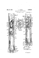
- Fig. 1 is an elevational sectional view showing a form of my invention which is adapted to engage and orient a core and raise it to the surface of the ground.
- Figs. 2, 3 and 4- are cross sectional views taken on the corresponding lines of Fig. 1.
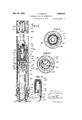
- Fig. 5 is an elevational sectional view through the form of my invention, which is a core drill incorporating the features of gripping and orienting the core and removing it to the surface of the ground.
- Fig. 6 is a cross section taken on the line 6-6 of Fig. 5.
- Fig. 7 is an elevational view showing a form of my invention in which the core drill, in addition to performing the function'of gripping the core for raising it to the surface of the ground and for orienting the core, also indicates the amount of inclination of the core while it is still attached to the bottom of the well.
- Fig. 8 is a vertical cross sectional view illustrating a form of my invention incorporating all of the features of the form of my invention shown in Fig. 7. In this form shown in Fig. 8, however, the orienting means is carried by the operating means of the invention.
- Figs. 9 and 10 are cross sectionalfviews taken on the corresponding lines of Fig. 8.
- Fig. 11 is an elevational view, partly in section, of the operating member and,illus trates the manner in which the operating member, as well as the inclination indicating means, is graduated.
- the numeral 20 represents a body having a threaded pin 21 at the upper end thereof, whereby it is attached to a supporting means such as a pipe 22, this pipe 22 extending upward from the device to the surface of the ground.
- the body 20 has an opening 23 for receiving a slidable member 24.
- the slidable member 24 has a core-receiving recess25, the lower end thereof being provided with a core-engaging means which is in the form of a plurality of depending fingers 26 provided with internal serrations 27 which are positioned to grip a core 28 which has been extended into the core-receiving recess 25.
- a core-engaging means which is in the form of a plurality of depending fingers 26 provided with internal serrations 27 which are positioned to grip a core 28 which has been extended into the core-receiving recess 25.
- the parts are shown in non-engaging position and may be brought into engaging position by depressing the body 20 relative to the slidable member 24. It will be noted that the slidable member 24 is resting on the bottom of the well, and further downward movement thereof is impossible.
- the lower end' of the body 20 has internal tapered faces 30 adapted to engage external tapered faces 31 of the fingers.
- a latch means in the form of dogs 32 and teeth 33 is provided respectively on the body 20 and slidable member 24.
- the dogs 32 are held in'engagement with the teeth 33 by leaf springs 34 or other suitable means. preventing the body 20 from moving upward relative to the slidable member 24, there is no danger of the core being released after it has once been engaged by the core-engaging means.
- a compass chamber 35 in the upper part of the slidable member 24 which accommodates a compass, or other orienting means.
- the numeral 36 represents a casing which is closed by a transparent plate 37, these parts being locked in place by a nut 38.
- the casing 36 and plate 37 rotatably support a compass needle 39.
- a compass needle 39 Directly below the outer ends of the compass needle 39 is an annular wall 40.
- a ring portion 42 of, an arresting means of my invention is also known as a ring portion 42 of, an arresting means of my invention.
- the next operation is to lift upward on the device by means of the supporting means, with the result that the core 28 is broken from the formation.
- the device is raised to the surface of the ground with the parts locked in inoperative position by the latching means associated with the body 20 and the slidable member 24.
- the next operation is to properly mark the core 28 so that after it is removed from the device the north-south plane will be known. Due to the fact that the upper part of the body 20 is provided with openings 50, the direction of the needle'39 may be determined and a suitable indicating mark corresponding therewith may be placed on the core.
- This form of the invention illustrates the rudiments of my invention and performs the two operations of gripping the core before it is severed from the bottom of the well and orienting it by an orienting means, the indication of which is observed and will inform the operator of the plane which is northsouth through the core prior to its being broken from the bottom of the well.
- the device may be used separately from the core barrel and is lowered into the well for operation afterthe core has been formed and after the core barrel has been removed.
- the orienting means is then operated by lowering the drill pipe, and the core-removing meansis therefore oriented. -The core is then broken from the bottom of the well and raised from the well.
- Figs. 5 and 6 I illustrate a form of my invention which is incorporated in a core drill.
- the numeral 60 represents a tubular body having at'its lower end cutter wings 61 and annularly ar ranged teeth 62, which surround the lower end of a core receiving opening 63.
- the parts 60 to 63 inclusive, may constitute the coreforming means of my invention.
- a core-receiving member'64 Placed within the tubular body 60 is a core-receiving member'64 which provides a core-receiving
- One of the operations which is performed by the apparatus is that of gripcavity 65 into which the core 28 is projected as it is formed by the operation of the core forming means.
- the lower end of the corereceiving member 64 is provided with a plurality of annularly arranged, depending fingers 66 having inner serrations 67 which are provided for the purpose of gripping the core.
- the depending fingers 66 constitute the core-engaging means of this form of my invention.
- the core-engaging means is moved inward into core-engaging position by virtue of a downward movement of the core-receiving member 61 relative to the core-forming means. lVhen this action occurs, the coreengaging fingers move downward towards the small end of the core-receiving opening 63, which is tapered, as shown, being surrounded by a conical face 69.
- the fingers 66 are provided with outer tapered faces which ride downward along the conical face 69, with the result that the fingers 66 are moved inward into the core-engaging position.
- a head structure 7 3 is secured to the upper end of the core-receiving member 64 and includes a lower part 74 and an upper part 75 threadedly secured together at 76.
- the head portion 73 is held in a centralized position inthe tubular body 60 and a seal is formed therearound by means of a packing ring 7 8.
- the lower end of the core-receiving member 6% is centralized by means of a lower packing ring 79.
- the lower part '74 is provided with a compass chamber 84, which rotatably supports the compass needle 85.
- a compass chamber 84 which rotatably supports the compass needle 85.
- Below the compass needle 85 is an annular wall 86, and above the compass needle 85 is a ring portion 87 of an arresting means of the invention.
- EX- tending upwardly from the ring portion 87 is an arm 88, the upper end of which has an engageable part 89, below which is a" spring 90 for retaining the arresting means in inoperative or non-arresting position.
- an operating member 92 having a valve 93 adapted to be dropped through the supporting means so that it may engage a valve seat 94 provided at the u )per end of the head structure 73.
- a valve seat 94 provided at the u )per end of the head structure 73.
- Dependmg from the valve 93 is a stem 95 which carries a plunger 96, which is resiliently retained in the position shown in Fig. 5 by means of a spring 97.
- the operating means When the operating means is dropped This increase in pressure causes the parts within the tubular'body 60 to move downward relative thereto. When this downward movement occurs, the fingers 66 are moved inward into core-engaging position, at which time the core formed by the core-forming means will be rigidly engaged.
- the valve 93 In order to provide for a small circulation of fluid, the valve 93 is provided with small passages 99.
- the second operation which is performed is that of operating the orienting means or compass. This is accomplished by the engaging of the lower end of the plunger 96 with the engageable part 89 of the arresting means. The arresting means is depressed and that it clamps the compass needle 85 against the annular wall 86.
- the chamber 84 is provided with glass walls 100, which provide windows in order that the position of the compass needle 85 may be observed.
- the position of the compass needle is then observed and the corresponding line is marked on the core, which will indicate the north-south plane of the core prior to the time that it was detached from the bottom of the Well.
- Fig. 7 the construction may be identical to that shown in Figs. 5 and 6 and described in connection therewith, with the exception of the upper part 75 of the head structure 73 and the operating member 92. The construction of these parts will now be described.
- the upper part 75 is provided with a relatively large central passage 105 which corresponds to passage 80 shownin Fig. 5, and has a plurality of radial passages 106 which correspond-to the radial passages 81 shown in Fig. 5.
- the operating means 92 is pro vided in the form of a body 107 having a rounded nose 108 which is adapted to engage the engageable part 89 of the arresting means. Threadedly secured at 110 is an upper part or stem 111, which may be provided contained therein.
- an inclination-indicating means in the form of an acid bottle 115, which is suitably sup-1 ported by rubber cushions 116.
- a resilient centralizing sleeve 118 Carried by the body 107 is a resilient centralizing sleeve 118. which is preferably made of rubber and which is preferably provided with longitudinal channels 119. The outer diameter of this centralizing member 118 is such'that it is a tight fit with the wall forming the centralizing passage 105.
- the operating means is placed in the upper end of the supporting means and allowed to gravitate through the fluid
- the lower end of the operating means enters the opening 105 and may move downward therein to approximately the position shown in Fig. 7. Due to the close fit between the centralizing member and the walls of the centralizing passage 105, there is suflicient friction to prevent the operating means from moving downward far enough to forcibly engage the arresting means which might result in injury thereto, or in injury to the orienting means.
- the presence of the operating means in the centralizing passage 105 causes a fluid pressure to be built up in the tubular body 60, this pressure causing two things to occur.
- the head structure and the core-receiving member 64 are moved downward in order to operate the core-engaging means as described in connection with Figs. 5 and 6.
- This causes the core to be rigidly engaged so that it will be immovable with respect to the core-receiving member.
- the arresting means is then forced downward in order to clamp the compass needle 85 against the annular wall 86, thus rendering it immovable relative to the core-receiving member 64 and the core, which is retained therein.
- the operating means is in its final position, it is supported sothat its axis is parallel to the axis of the device and concentric to the axis of the core.
- the acid bottle 115 is filled with an etching acid 120 such as hydrofluoric acid, the level of which will assume ahorizontal position and etch a horizontal linein the wall of the acid bottle 115.
- the parts are allowed to remain quiet until a certain period of time has lapsed whici will permit the etching fluid to spend itsel
- the parts are then removed to the surface of the ground and the inner assembly is removed from the tubular body 60.
- the core is then marked to indicateits north-south plane, as explained in connection with the device shown in Figs. 5 and 6.
- the north-south plane of the acid bottle 115 may be accomplishcd in any suitable manner such, for example, as providing graduations 122 on the operating means and graduations 123 on the acid bottle. WVhen the acid bottle is placed" in the operating means, zero graduation on the acid bottle is aligned with the zero graduation on the operating means. Before removing the operating means from the central passage 105, the graduations in alignment with the north end of the compass are observed. After the acid bottle has been removed from the operating means and after the core has been removed from the corereceiving member 64, the graduations corresponding to the north end of the compass needle 85 are placed in alignment with the north end of the line representing the northsouth plane of the core.
- the core and the acid bottle are placed concentric and the core is then so placed that the line etched in the acid bottle is horizontal. This will cause the core to occupy the same position of inclination which it occupied in the well.
- the core By arranging the north-south plane parallel to the magnetic north-south, the core will be in its proper oriented position.
- the head structure 73 may be made a single part 130, which is .secured at 131 to the upper end of the core-receiving member 64.
- the part 130 provides the central passage 105, and the radial passages 106, which correspond to those passages shown in Fig. 7.
- the .body 107 of the operating means 92 has a lower compass chamber 132, and the lower end is threaded so that a removable nose 133 may be removably attached thereto.
- a compass needle 135 Rotatably supported in the pocket 132 is a compass needle 135 above which is an annular wall 136. Below the compass needle 135 and the annular wall 136 is a ring portion 138 of an arresting means of theinvention. An arm 139 extends downward from the ring portion'138 through the nose 133 and projects from the lower end thereof, the lower projecting end being provided with an engageable portion 140.
- the wall surrounding the pocket 132 is provided with openings in which transparent members 142 are placed in order to provide windows through which the position of the compass needle 135 may be observed.
- Graduations similar to 122 are placed onthe windows 142 and will be referred to by the numeral 144.
- the graduations 123 on the acid bottle 115 and the graduations 144 are arranged so that the zero marks are in alignment.
- the upper end of the stem 111 is provided with an upper guide means 146 having wings 147 which provide fluid passages and provide centralizing faces 148.
- Carried by the upper part of the tubular body is a guide sleeve 150 having a cylindrical face 151 engageable by the face 148 when the apparatus is in the position shown in Fig. 8.
- This upper guide means cooperates with the lower guide means, comprising the ring 118 and the cylindrical wall forming the central passage 105, to hold the operating means concentric to the axis of the core 28.
- the operation closely resembles that of the form shown in Fig. 7.
- the device is operated so that the core-forming means forms the core 28 which extends upward into the core-receiving member 64. WVhen a sufiicient core has been formed, drilling operations are ceased.
- the acid bottle is then filled with acid and placed within the cavity 114 of the operating means with the zero mark thereof in alignment with the zero mark of the graduations 144 and the operating means is introduced into the upper end of the supporting means and permitted to gravitate to the lower end of the well.
- the operating means will enter the central passage 105 a distance depending upon the rate at which it is travelling downward through the well.
- the friction between the rubber sleeve 118 and the wall of the central passage 105 is, however, sufiicient to prevent the operating means from dropping downward to the extent that the engageable portion 140 of the arresting means will forcibly strike the wall 152 of the part 130.
- the parts are allowed to remain in this position until the acid 120 has etched a level mark on the'w'all of the acid bottle 115.
- the parts are then removed to the surface of the ground and the structure within the tubular body 60 is removed therefrom.
- the position of the compass needle 135 is observed and the core 28 is provided with a mark which indicates the north-south plane of the core.
- the operating means may then be removed and dismantled so that the acid bottle can be .tion to which the compass needle 13:) previously pointed is turned to the north.
- the core and acid bottle are then tilted so that the level line etched in the bottle by the acid is in a horizontal plane.
- the core then occupies its true oriented position and its true angle of inclination.
- the direction-indicating means illustrated is a magnetic compass but an equivalent of the magnetic compass, such as a gyroscope, is intemled to be included within the meaning of the expression direction-indicating means,.
- the acid bottle employed in the forms of the invention shown is one form of direction-indicating means, but this latter expression includes any of the equivalent indicating means such as photographic or pendulum means.
- position-indicating means is used in the claims to mean either the inclinationindicating means or the orienting means.
- both of these means are position-indicating means. and in the arrangement of the parts in my invention the positions of these various indicating means may be changed without departing from the spirit and scope of the invention. Attention is called to the fact that in Figs. 5 and 7 the compass or orienting means is at all times adjacent to the core barrel, while'in Fig. 8 the compass is carried by the operating member which is lowered through the drill pipe.
- position-indicating-means is used broadly, it is intended to cover either the compass or the acid bottle or' its equiva- I direction of inclination-were not used, then lent, and in thismanner I am enabled to broadly define my invention.
- the term operating means is used to refer to the part which is dropped along the 'drill pipe or sup- 5 porting means whereby the position-imlicating means may be operated.
- My invention may be used in its entirety, or various of the elements of the device may be used apart from the whole apparatus, and I do not,'therefore, wish my invention to be construed as being limited to the entire combination.” To illustrate-my meaning, I will refer. to various combinations less than the invention in its entirety which may be beneficially employed.
- the core may be formed by a special core cutter andleft' protruding upward from the bottom of the -well.' In this event only the core gripper and the directionindicating means'such as shown in Fig. 1 need be used, or operations includinggripping the core, determining the directional position of the core, and breaking the core from the formation.
- This apparatus may be used with or without the inclination-indicating 25- mcans, depending on whether or not -rit is necessary to determine the inclination of the 'well. In some cases where there areavailable core samples of surrounding wells, it may not be necessary to use the orienting means and in such-instance the core-gripping means and the inclination means may be used without the other elements.
- the orienting means or compass is used-without the tread bottle or inclination-indicating means, the geologist willknow how to. orientes the core and will know what ro'tationalfp the support means for the' core barrel.
- the operating means which I provide, which operating means may be employed in dependently of other features of the, invention.
- the operating means need not at all times be employed to operate the core-gripping means of the invention.
- the core barrel may be provided with jother types of core-gripping means.
- the manner of operating the position-indicating means, ,however, is quite important and permits the acid bottle or compass or other orienting means-to be opei'ated at the will of the operator. This is accomplished by lowering a member along form of the invention shown in Fig. 5, the operating means is nothing more than a body which is allowed'to drop through the drill pipe andas a meansfor causing the compass to operate.
- the means is provided with an acid bottle in one instance and an acid bottle anda compass in the other instance showing that the operating means may carry the position-indicating means if desired.
- the device includes the inclination-indicatingmeans and the direction-indicating means, and these parts may be employed without the coreforming and core-engaging means for the purpose of determining the amotipt and di- I define my invention in t e following claims and intend that the claims be con In the strued with due regard to the foregoing state ments of the scope of my invention.
- core-engaging means adapt- 'ed to engage a core and break it from the bottom f a well; means for causing the operation of said-core-enga ing means, means for elevating said core an core engaging means;
- core-forming means for forming a, core
- core-engaging means for engaging said core
- direction-indicating means means for operating said core-engaging means
- means forelevating the core and means for locking said direction-indicating means means for locking said direction-indicating means.
- core-forming means for forming a core
- core-engaging means for engaging said core
- orienting means for orienting said core
- supporting means for said core-forming means
- operating means adapted to be lowered along said supporting means to operate said core-engaging means and said orienting means.
- orienting means for orienting said core; a supporting means for said core-forming means; operating means adapted to be lowered along said supporting means to operate said core-engaging means and said orienting means; and an inclinationindicating means carried by said operating means.
- core-forming means for forming a core
- core-engaging means for engaging said core
- orienting means for orienting said core
- a supporting means for said core-forming means
- operating means adapted to be lowered along said supporting means to operate said core-engaging means and said orienting means, said orienting means being carried by said operating means;
- core-receiving means for receiving a core
- co re engaging means for engaging said core
- inclmatlon-indicating means adjacent to said core-receiving means for indicating the inclination of said corereceiving means
- a supporting means for said core-receiving means
- an operating means adapted to be lowered along said supporting means for causing the operation of said inclination-indicating means
- orienting --means carried by said operating means
- core-receiving means for receiving a core
- core-engaging means forengaging said core
- a supporting means for supporting said core-receiving means
- position-indicating means adapted to be lowered along said supporting means for indieating-the position of said core-receiving means.
- orienting means adapted to be lowered along said supporting means for orienting said corereceiving means.
- core-receiving means for receiving a core
- core-engaging means for engaging a core
- orienting means supporting means for said core-receiving means
- operating means adapted to be lowered along said supporting means whereby said orient-' ing means will be permitted to orient said 22.
- core-recelvmg means for recelving a core
- core-engaging means for engaginga core
- position-indicating means including means for indicating the amount and directionof inclination
- supporting means for said core-receiving means and operating means adapted to be lowered along said supporting means whereby said position-indicating means will bepermitted to indicate the position of said core-receiving means.
- core-receiving means for receivinga core
- core-engaging means for engaging a core
- inclination-indicating means for supporting means for ⁇ said core-receiving means
- operating means adapted to be lowered along said supporting means whereby said inclination-indicating means will be permitted to indicate the inclination of said core-receiving means, said inclination-indicating means being carried by said I operating means.
Landscapes
- Life Sciences & Earth Sciences (AREA)
- Engineering & Computer Science (AREA)
- Geology (AREA)
- Mining & Mineral Resources (AREA)
- Physics & Mathematics (AREA)
- Environmental & Geological Engineering (AREA)
- Fluid Mechanics (AREA)
- General Life Sciences & Earth Sciences (AREA)
- Geochemistry & Mineralogy (AREA)
- Dental Tools And Instruments Or Auxiliary Dental Instruments (AREA)
Description
May 24, 1932. J. A. ZUBLIN APPARATUS FOR CORE ORIENTATION Filed March 17, 1950 5 Sheets-Sheet l //v [/EN 7'0 3 Johw A Zuau/v f May 24, 1932. J, A. ZUBLIN APPARATUS FOR coma ORIENTATION s Shee ts-Sheet Filed March 17, 1950 l/w/a/vro/e: May/v ,4. Zaau $1 I'l I uazaarai- 1 w 1 May 24, 1932. J. A. ZUBLIN APPARATUS FOR CORE ORIENTATION Filed March '17, 1950 3 Sheets-Sheet s jwm w H8 N l/E/V Toe I/OH/V ,4. Z 054 ml Patented May 24, 1932 PATENT OFFICE JOHN A. ZUBLIN, OF LOS ANGELES, CALIFORNIA APPARATUS FOR CORE ORIENTATION Application filed March 17, 1930. Serial No. 436,512.
My invention relates to apparatus whereby a core may be formed and removed from a well in such a manner and by such means that the core is oriented prior to its being detached from the bottom of the well, and to apparatus whereby the inclination to vertical of the core may also be determined prior to the core being detached from the bottom of the well. My invention further resides in certain features of construction and in. subcombinations of the whole combination.
So that my invention may be understood and the advantages appreciated, I will briefly explain the pertinent part of the core-taking art.
The proper exploitation of an oil field requires that the direction of the underlying earth structure be ascertained in order that the location of the most prolific part of the oil sand may be located. Many oil bearing formations and layers are not horizontal, but are inclined. If the inclination of the strata can be determined, the geologist may draw his conclusions as to the location of the largest amount of oil. As a rule, water accumulates in the lower part of the oil bearing structure and the oil in the upper part. Therefore, if the direction of inclination be m ascertained, drilling may be performed at the higher part of the oil bearing formation.
It is present practice during the drilling of an oil-well to take from the well a sample core which will advise the geologist of the strata formations; but in order to, ascertain the direction of inclination it is necessary to drill a plurality of wells and take sample cores from them and to compare'these cores. This is because of the fact that at present the core-taking art does not have a device which will orient the core and determine its inclination to vertical prior to the detaching of said core from the'bottom of thewell in order that the geologist may, in making his calculations, know the exact position which the core occupied in the well, which would. of course, inform him of the direction of inclination of the strata as well as the nature of the strata. My invention consists of apparatus in which the core is broken from the bottom of the well and oriented so that at the top of the well it may be placed in a position corresponding to the position which it occupied in the well. The core then occupies its true north and south position and the geologist may draw his conclusion without reference to cores from adjacent wells.
When the well is vertical, the core obtaine bythe above apparatus will be placed with its axis on the vertical and accurate indications as to the direction of the inclination of the strata will be given, but where the portion of the hole from which the core is removed is at an angle to the vertical, the core must be arranged during its examination by the geologist in a position corresponding to the one it occupied in the Well, or at least the amount and direction of inclination should be known so that they may be considered during the making of calculations. My invention provides an apparatus in which the amount of inclination and the direction of inclination are indicated and the orientation ofthe core is accomplished, which enables the core to be placed in a position at the surface of the ground which exactly corresponds to the position it occupied in the well.
'A broad concept of my invention resides in a device for determining the inclination of the. core prior to its detachment from the bottom of the well. This broad concept provides a core-removing means which may be disposed in a given position relative to the core which has been formed at the bottom of the well. The core-removing means preferably has a core-receiving chamber for accommodating the core. Associated with the core-removing means is a core-gripping means which is operable to grip the core to render it immovable relative to the core-removing means. Operable in connection with these elements is an inclination-determining means for determining the inclination of the core-removing means.
A further'broad and very important concept of my present invention resides in a device for obtaining a core from a well in such a manner that the amount of inclination of the core andthe direction of inclination of l the core may be known. When such information is obtained with the core, a geologist may arrange the core in the same position in his laboratory as the core occupied in the well.
He may set the core on its proper inclination and proper direction of inclination. This will enable him to know exactly the position of the lower strata and will enable him-to calculate where the oil dome or anticline is located.
This portion of my invention is preferably embodied in apparatus whereby the core may be obtained and its amount of inclination and direction of inclination recorded and then moved to the surface of the ground where the recorded amount of inclination and recorded direction of inclination may be utilized to place the core in position at the surface of the ground which corresponds with the position which it occupied in the well.
My invention further provides an operating means whereby the inclination-indicating means and the orienting means, that is, the direction of inclination-indicating means, may be operated at the will of the operator. This portion of my invention is embodied in an arrangement whereby an operating means may be lowered through the drill pipe and cause an operation of the indicating or recording means at the bottom of the hole.- My invention may take various forms. The inclination-indicating means or the directionindicating means, both of which constitute a position-indicating means, may both be located in the core barrel and may be operated by dropping a body into the drill pipe or other pipe by which the core barrel is supported, or may be operated by other means,
such as an increase in pressure. or by .some means in the exterior of the drill pipe. On the other hand, one or both of these positionindicating means may be on the operating member which is dropped through the drill pipe, and the other position-indicating means may be positioned adjacent tothe core barrel.
Ijattach considerable importance to the specific arrangement of the elements of my device, which makes for simplicity of construction and positiveness of operation. I provide a combination in which the coreforming operation may be performed until a sufiicient core has been made. Then by a single operation the core is engaged to render it immovable in the device and the orienting and inclination-determining means is caused to orient the core.
As a preferred form of this part of my invention, I provide an operating means which may be lowered into the pipe or other support means for the device. which operating means will operate the core-engaging means and the orienting and inclination-determining means when it reaches the device.
My invention provides one form of device in which the orienting means is dropped into the device after the core is formed. The value of this design is in the saving of the orienting and inclination-determining means from drilling vibrations.
A portion of my invention may be used separately as an orienting and inclination recording device. This part of my invention provides a device which may be dropped through the drill pipe to the lower end thereof just prior to the removal of the drill pipe. At the lower end of the drill pipe the device will operate to record the direction of inclination and the amount of inclination from vertical of the well.
I will now describe in detail the important forms of my invention and during my description thereof the important features and the advantages will be pointed out. 7
Referring to the drawings, in which I illustrate my invention:
Fig. 1 is an elevational sectional view showing a form of my invention which is adapted to engage and orient a core and raise it to the surface of the ground.
Figs. 2, 3 and 4- are cross sectional views taken on the corresponding lines of Fig. 1.
Fig. 5 is an elevational sectional view through the form of my invention, which is a core drill incorporating the features of gripping and orienting the core and removing it to the surface of the ground.
Fig. 6 is a cross section taken on the line 6-6 of Fig. 5.
Fig. 7 is an elevational view showing a form of my invention in which the core drill, in addition to performing the function'of gripping the core for raising it to the surface of the ground and for orienting the core, also indicates the amount of inclination of the core while it is still attached to the bottom of the well.
, Fig. 8 is a vertical cross sectional view illustrating a form of my invention incorporating all of the features of the form of my invention shown in Fig. 7. In this form shown in Fig. 8, however, the orienting means is carried by the operating means of the invention.
Figs. 9 and 10 are cross sectionalfviews taken on the corresponding lines of Fig. 8.
Fig. 11 is an elevational view, partly in section, of the operating member and,illus trates the manner in which the operating member, as well as the inclination indicating means, is graduated.
Referring particularly to Figs. 1 to 4, inclusive, the numeral 20 represents a body having a threaded pin 21 at the upper end thereof, whereby it is attached to a supporting means such as a pipe 22, this pipe 22 extending upward from the device to the surface of the ground. The body 20 has an opening 23 for receiving a slidable member 24.
The slidable member 24 has a core-receiving recess25, the lower end thereof being provided with a core-engaging means which is in the form of a plurality of depending fingers 26 provided with internal serrations 27 which are positioned to grip a core 28 which has been extended into the core-receiving recess 25. In Fig. 1, the parts are shown in non-engaging position and may be brought into engaging position by depressing the body 20 relative to the slidable member 24. It will be noted that the slidable member 24 is resting on the bottom of the well, and further downward movement thereof is impossible. The lower end' of the body 20 has internal tapered faces 30 adapted to engage external tapered faces 31 of the fingers. The
engagement of the faces 30 and 31 prevents further downward movement of the body 20 without an inwardly yielding of the fingers 26. When the fingers are forced inward, the serrations 27 are caused to engage the core 28 and to lock it so that it is immovable with respect to the slidable member 24.
In order to prevent the body 20 from mov ing upward relative to the slidable member 24, a latch means in the form of dogs 32 and teeth 33 is provided respectively on the body 20 and slidable member 24. The dogs 32 are held in'engagement with the teeth 33 by leaf springs 34 or other suitable means. preventing the body 20 from moving upward relative to the slidable member 24, there is no danger of the core being released after it has once been engaged by the core-engaging means. I
In order to accomplish an orientation of the core 28, I provide a compass chamber 35 in the upper part of the slidable member 24 which accommodates a compass, or other orienting means. The numeral 36 represents a casing which is closed by a transparent plate 37, these parts being locked in place by a nut 38. The casing 36 and plate 37 rotatably support a compass needle 39. Directly below the outer ends of the compass needle 39 is an annular wall 40. Above the compass needle 39 and in alignment with the annular wall 40 is a ring portion 42 of, an arresting means of my invention. Extending upward from the ring portion 42 .is an arm 44, the upper end of which is engaged by a coil spring 45 which resiliently retains the arresting means in inoperative or non-arresting position. Carried by the body 20 is a plunger 46 which is held II; a downward position by means of a spring 4 When the body 20 is moved downward relative to the slidable member 24, the lower end of the plunger 46 comes into engagement with the upper end of the arresting means and moves it downward until the ring portion 42 of the'arresting means clamps the compass needle 39 against the annular wall 40. This arresting action occurs at the same time that the core is engaged. The co-mpassneedle 39 is rigidly clamped in a position in which it indicates magnetic north and thus indicates which plane in the core 28 is north and south prior to the time that the core isbroken from the bottom of the well.
The next operation is to lift upward on the device by means of the supporting means, with the result that the core 28 is broken from the formation. The device is raised to the surface of the ground with the parts locked in inoperative position by the latching means associated with the body 20 and the slidable member 24. The next operation is to properly mark the core 28 so that after it is removed from the device the north-south plane will be known. Due to the fact that the upper part of the body 20 is provided with openings 50, the direction of the needle'39 may be determined and a suitable indicating mark corresponding therewith may be placed on the core.
This form of the invention illustrates the rudiments of my invention and performs the two operations of gripping the core before it is severed from the bottom of the well and orienting it by an orienting means, the indication of which is observed and will inform the operator of the plane which is northsouth through the core prior to its being broken from the bottom of the well. The device may be used separately from the core barrel and is lowered into the well for operation afterthe core has been formed and after the core barrel has been removed.
The apparatus just described in detail performs the broad concept of my invention. From the foregoing description of the construction and operation of this form of the invention it will be noted that the apparatus which includes the core-removing means is lowered into the position shown in Fig. 1, and
therefore is disposed so as to occupy a given position with relation to the core, 28. The orienting means is then operated by lowering the drill pipe, and the core-removing meansis therefore oriented. -The core is then broken from the bottom of the well and raised from the well.
ping the core prior to the actuation or simulmeans. This is accomplished by forcing the jaws or fingers 26 inwardly so as to rigidly grip the core and rigidly secure it to the coreremoving means.
In Figs. 5 and 6, I illustrate a form of my invention which is incorporated in a core drill. Referring to these figures, the numeral 60 represents a tubular body having at'its lower end cutter wings 61 and annularly ar ranged teeth 62, which surround the lower end of a core receiving opening 63. The parts 60 to 63 inclusive, may constitute the coreforming means of my invention. Placed within the tubular body 60 is a core-receiving member'64 which provides a core-receiving One of the operations which is performed by the apparatus is that of gripcavity 65 into which the core 28 is projected as it is formed by the operation of the core forming means. The lower end of the corereceiving member 64 is provided with a plurality of annularly arranged, depending fingers 66 having inner serrations 67 which are provided for the purpose of gripping the core. The depending fingers 66 constitute the core-engaging means of this form of my invention. The core-engaging means is moved inward into core-engaging position by virtue of a downward movement of the core-receiving member 61 relative to the core-forming means. lVhen this action occurs, the coreengaging fingers move downward towards the small end of the core-receiving opening 63, which is tapered, as shown, being surrounded by a conical face 69. The fingers 66 are provided with outer tapered faces which ride downward along the conical face 69, with the result that the fingers 66 are moved inward into the core-engaging position.
A head structure 7 3 is secured to the upper end of the core-receiving member 64 and includes a lower part 74 and an upper part 75 threadedly secured together at 76. The head portion 73 is held in a centralized position inthe tubular body 60 and a seal is formed therearound by means of a packing ring 7 8. The lower end of the core-receiving member 6% is centralized by means of a lower packing ring 79. During the operation of the coreforming means, a rotary mud or washing fluid is pumped downward through the supporting means and passes through the central passage 80 and lateral passages 81 of the upper part 75 of the head structure 73 and into the interior of the tubular body 60 around the core-receiving member 64. This fluid then passes through small passages 82,
being directed thereby against the cutter wings 61 for washing the cuttings awayand removing them to the surface of the ground. The lower part '74 is provided with a compass chamber 84, which rotatably supports the compass needle 85. Below the compass needle 85 is an annular wall 86, and above the compass needle 85 is a ring portion 87 of an arresting means of the invention. EX- tending upwardly from the ring portion 87 is an arm 88, the upper end of which has an engageable part 89, below which is a" spring 90 for retaining the arresting means in inoperative or non-arresting position.
The form now being described includes an operating member 92 having a valve 93 adapted to be dropped through the supporting means so that it may engage a valve seat 94 provided at the u )per end of the head structure 73. Dependmg from the valve 93 is a stem 95 which carries a plunger 96, which is resiliently retained in the position shown in Fig. 5 by means of a spring 97.
When the operating means is dropped This increase in pressure causes the parts within the tubular'body 60 to move downward relative thereto. When this downward movement occurs, the fingers 66 are moved inward into core-engaging position, at which time the core formed by the core-forming means will be rigidly engaged. In order to provide for a small circulation of fluid, the valve 93 is provided with small passages 99. The second operation which is performed is that of operating the orienting means or compass. This is accomplished by the engaging of the lower end of the plunger 96 with the engageable part 89 of the arresting means. The arresting means is depressed and that it clamps the compass needle 85 against the annular wall 86. This locks the compass needle relative to the core-receiving member and since the core is rigidly gripped by the the ring portion 87 is moved downward so core-engaging means, the compass needle is also locked relative to the core so that it indicates the north-south plane of the core.
After the parts have been thus operated, they are raised to the surface of the ground and the structure enclosed by the tubular body 60 is removed, care being taken not to disturb the position of the operating means, nor the position of the core within the corereceiving member. As illustrated in Fig. 6, the chamber 84 is provided with glass walls 100, which provide windows in order that the position of the compass needle 85 may be observed. The position of the compass needle is then observed and the corresponding line is marked on the core, which will indicate the north-south plane of the core prior to the time that it was detached from the bottom of the Well.
In Fig. 7, the construction may be identical to that shown in Figs. 5 and 6 and described in connection therewith, with the exception of the upper part 75 of the head structure 73 and the operating member 92. The construction of these parts will now be described.
The upper part 75 is provided with a relatively large central passage 105 which corresponds to passage 80 shownin Fig. 5, and has a plurality of radial passages 106 which correspond-to the radial passages 81 shown in Fig. 5. The operating means 92 is pro vided in the form of a body 107 having a rounded nose 108 which is adapted to engage the engageable part 89 of the arresting means. Threadedly secured at 110 is an upper part or stem 111, which may be provided contained therein.
Contained in a cavity 114 of the body 107 is an inclination-indicating means in the form of an acid bottle 115, which is suitably sup-1 ported by rubber cushions 116.
Carried by the body 107 is a resilient centralizing sleeve 118. which is preferably made of rubber and which is preferably provided with longitudinal channels 119. The outer diameter of this centralizing member 118 is such'that it is a tight fit with the wall forming the centralizing passage 105.
After the device has been operated to form the core, the operating meansis placed in the upper end of the supporting means and allowed to gravitate through the fluid The lower end of the operating means enters the opening 105 and may move downward therein to approximately the position shown in Fig. 7. Due to the close fit between the centralizing member and the walls of the centralizing passage 105, there is suflicient friction to prevent the operating means from moving downward far enough to forcibly engage the arresting means which might result in injury thereto, or in injury to the orienting means. The presence of the operating means in the centralizing passage 105 causes a fluid pressure to be built up in the tubular body 60, this pressure causing two things to occur. In the first place, the head structure and the core-receiving member 64 are moved downward in order to operate the core-engaging means as described in connection with Figs. 5 and 6. This causes the core to be rigidly engaged so that it will be immovable with respect to the core-receiving member. As the pressure builds up it will force the operating means downward in the centralizing passage 105 until the nose 108 engages the'engageable part 98 of the arresting means. The arresting means is then forced downward in order to clamp the compass needle 85 against the annular wall 86, thus rendering it immovable relative to the core-receiving member 64 and the core, which is retained therein.
\Vhen the operating means is in its final position, it is supported sothat its axis is parallel to the axis of the device and concentric to the axis of the core. The acid bottle 115 is filled with an etching acid 120 such as hydrofluoric acid, the level of which will assume ahorizontal position and etch a horizontal linein the wall of the acid bottle 115. The parts are allowed to remain quiet until a certain period of time has lapsed whici will permit the etching fluid to spend itsel The parts are then removed to the surface of the ground and the inner assembly is removed from the tubular body 60. The core is then marked to indicateits north-south plane, as explained in connection with the device shown in Figs. 5 and 6.
It is further necessary in this form of the invention to indicate the north-south plane of the acid bottle 115. This may be accomplishcd in any suitable manner such, for example, as providing graduations 122 on the operating means and graduations 123 on the acid bottle. WVhen the acid bottle is placed" in the operating means, zero graduation on the acid bottle is aligned with the zero graduation on the operating means. Before removing the operating means from the central passage 105, the graduations in alignment with the north end of the compass are observed. After the acid bottle has been removed from the operating means and after the core has been removed from the corereceiving member 64, the graduations corresponding to the north end of the compass needle 85 are placed in alignment with the north end of the line representing the northsouth plane of the core. The core and the acid bottle are placed concentric and the core is then so placed that the line etched in the acid bottle is horizontal. This will cause the core to occupy the same position of inclination which it occupied in the well. By arranging the north-south plane parallel to the magnetic north-south, the core will be in its proper oriented position.
The form of my invention illustrated in 'Figs. 8 to 11, inclusive, difli'ers from the form shown in Fig. 7 by the orienting means being carried in the operating means 92. In this form now being described the head structure 73 may be made a single part 130, which is .secured at 131 to the upper end of the core-receiving member 64. The part 130 provides the central passage 105, and the radial passages 106, which correspond to those passages shown in Fig. 7. The .body 107 of the operating means 92 has a lower compass chamber 132, and the lower end is threaded so that a removable nose 133 may be removably attached thereto. Rotatably supported in the pocket 132 is a compass needle 135 above which is an annular wall 136. Below the compass needle 135 and the annular wall 136 is a ring portion 138 of an arresting means of theinvention. An arm 139 extends downward from the ring portion'138 through the nose 133 and projects from the lower end thereof, the lower projecting end being provided with an engageable portion 140.
The wall surrounding the pocket 132 is provided with openings in which transparent members 142 are placed in order to provide windows through which the position of the compass needle 135 may be observed. Graduations similar to 122 are placed onthe windows 142 and will be referred to by the numeral 144. As pointed out with regard. to the form shown in- Fig. 7, the graduations 123 on the acid bottle 115 and the graduations 144 are arranged so that the zero marks are in alignment.
The upper end of the stem 111 is provided with an upper guide means 146 having wings 147 which provide fluid passages and provide centralizing faces 148. Carried by the upper part of the tubular body is a guide sleeve 150 having a cylindrical face 151 engageable by the face 148 when the apparatus is in the position shown in Fig. 8. This upper guide means cooperates with the lower guide means, comprising the ring 118 and the cylindrical wall forming the central passage 105, to hold the operating means concentric to the axis of the core 28.
In this form of the invention the operation closely resembles that of the form shown in Fig. 7. The device is operated so that the core-forming means forms the core 28 which extends upward into the core-receiving member 64. WVhen a sufiicient core has been formed, drilling operations are ceased. The acid bottle is then filled with acid and placed within the cavity 114 of the operating means with the zero mark thereof in alignment with the zero mark of the graduations 144 and the operating means is introduced into the upper end of the supporting means and permitted to gravitate to the lower end of the well. The operating means will enter the central passage 105 a distance depending upon the rate at which it is travelling downward through the well. The friction between the rubber sleeve 118 and the wall of the central passage 105 is, however, sufiicient to prevent the operating means from dropping downward to the extent that the engageable portion 140 of the arresting means will forcibly strike the wall 152 of the part 130.
When the operating means is in the position shown in Fig. 8, the central passage 105 is obstructed and a fluid pressure will be built up behind the operating neans which will cause it to move downward in the central passage 105 so that the engageable portion 140 will engage the wall 152, and there will at this time be a relative movement between the ar resting means and the other parts of the operating means. The ring portion 188 will engage the compass needle 135 and clamp it against the annular wall 136.
Further action which takes place is that the fluid pressure built up will cause the entire structure supported within the tubular body 60 to move downward so that the core-engag ing means will be caused to move inward and engage the core 28 so that it will be immovable with respect to the core-receiving member 64.
The parts are allowed to remain in this position until the acid 120 has etched a level mark on the'w'all of the acid bottle 115. The parts are then removed to the surface of the ground and the structure within the tubular body 60 is removed therefrom. The position of the compass needle 135 is observed and the core 28 is provided with a mark which indicates the north-south plane of the core. It
is also observed which graduation the north end of the-compass needle 135 is pointed to. The operating means may then be removed and dismantled so that the acid bottle can be .tion to which the compass needle 13:) previously pointed is turned to the north. The core and acid bottle are then tilted so that the level line etched in the bottle by the acid is in a horizontal plane. The core then occupies its true oriented position and its true angle of inclination.
The detailed description of my invention just completed is intended to disclose the essence of my invention and the details of construction to the extent of development at the. present time. It is recognized that various changes will undoubtedly be made and I therefore emphasize that this description is primarily for the purpose of advising those skilled in the art of my invention. and it should not be construed as intending to limit me to the forms shown herein.
I fully realize that the different elements shown and described may be replaced by others of equal suitableness in the apparatus, and for this reason I stress that I intend the terms used in the claims to mean not only the particular element herein which is referred to by the term used, but also to its equivalents. As an illustration, the direction-indicating means illustrated is a magnetic compass but an equivalent of the magnetic compass, such as a gyroscope, is intemled to be included within the meaning of the expression direction-indicating means,. The acid bottle employed in the forms of the invention shown is one form of direction-indicating means, but this latter expression includes any of the equivalent indicating means such as photographic or pendulum means. The term position-indicating means is used in the claims to mean either the inclinationindicating means or the orienting means. Broadly speaking, both of these means are position-indicating means. and in the arrangement of the parts in my invention the positions of these various indicating means may be changed without departing from the spirit and scope of the invention. Attention is called to the fact that in Figs. 5 and 7 the compass or orienting means is at all times adjacent to the core barrel, while'in Fig. 8 the compass is carried by the operating member which is lowered through the drill pipe. When the term position-indicating-means is used broadly, it is intended to cover either the compass or the acid bottle or' its equiva- I direction of inclination-were not used, then lent, and in thismanner I am enabled to broadly define my invention. The term operating means is used to refer to the part which is dropped along the 'drill pipe or sup- 5 porting means whereby the position-imlicating means may be operated.
My invention may be used in its entirety, or various of the elements of the device may be used apart from the whole apparatus, and I do not,'therefore, wish my invention to be construed as being limited to the entire combination." To illustrate-my meaning, I will refer. to various combinations less than the invention in its entirety which may be beneficially employed.- The core may be formed by a special core cutter andleft' protruding upward from the bottom of the -well.' In this event only the core gripper and the directionindicating means'such as shown in Fig. 1 need be used, or operations includinggripping the core, determining the directional position of the core, and breaking the core from the formation. This apparatus may be used with or without the inclination-indicating 25- mcans, depending on whether or not -rit is necessary to determine the inclination of the 'well. In some cases where there areavailable core samples of surrounding wells, it may not be necessary to use the orienting means and in such-instance the core-gripping means and the inclination means may be used without the other elements.
Although the different parts of my invention may beused separately, it should be distinctly understood that the different elements constitute a meritorious combination and are used in preference to using the different parts of the invention. I now have particular reference to the combination which provides for the indicating or recording of the inclination and direction of inclination of the. core-removing means or core barrel. When both of-these position-indicating means are used the exact position of the core will be indicated, and'the geologist'may place the core in a position at the surface of the ground which exactly corresponds with the position of the core in the bottom of the well. If the inclination means were used and the orienting means or the means for'determining the the geologist would know ,,th e inclination of the core but would not knew in which direction it was inclined. Therefore, the geologist will not know in' which directionthe strata is inclined or inwhich direction from the well the nil; ,dome or anticline is located.-
It will therefore be seen that without the orienting means, the inclination-indicating means which gives the amount of inclination is not very helpful." On the otherhand, if-
the orienting means or compass is used-without the tread bottle or inclination-indicating means, the geologist willknow how to. orientes the core and will know what ro'tationalfp the support means for the' core barrel.
rection. of inclination of the the well. 1
whether the core is vertical or inclined, and
if it is inclined he will not known the amount of inclination nor the direction of inclination. In order to obtain a complete record, it is in my opinion necessary not only to 0bt-ain the core, but to simultaneously record or determine the amount of inclination of the core and at the same time the directiomof inclinat on of the core.
I desire to again emphasize the importance of the operating means which I provide, which operating means may be employed in dependently of other features of the, invention. For example, the operating means need not at all times be employed to operate the core-gripping means of the invention. In fact, in some instances the core barrel may be provided with jother types of core-gripping means. The manner of operating the position-indicating means, ,however, is quite important and permits the acid bottle or compass or other orienting means-to be opei'ated at the will of the operator. This is accomplished by lowering a member along form of the invention shown in Fig. 5, the operating means is nothing more than a body which is allowed'to drop through the drill pipe andas a meansfor causing the compass to operate. In Figs. 7 'and.8 the means is provided with an acid bottle in one instance and an acid bottle anda compass in the other instance showing that the operating means may carry the position-indicating means if desired.
As a further illustration, the device includes the inclination-indicatingmeans and the direction-indicating means, and these parts may be employed without the coreforming and core-engaging means for the purpose of determining the amotipt and di- I define my invention in t e following claims and intend that the claims be con In the strued with due regard to the foregoing state ments of the scope of my invention.
I claim as my invention:
1. In apparatus of the class described, the combination of: core-engaging means; orienting means; and common operating means for operating saidcore engaging means and said orienting means. i p
2. In apparatus of the class described, the
combination'of: core-engaging means adapt- 'ed to engage a core and break it from the bottom f a well; means for causing the operation of said-core-enga ing means, means for elevating said core an core engaging means;
and orienting means adapted to orient said core before it is broken from the bottom of 3. 'In apparatus of the combinatioirgij of core-forming means ;for
class described, the
5 means for operating said core-engaging means and said' orienting means.
4. In apparatus of the class described, the combination of: core-forming means for forming a, core; core-engaging means for engaging said core; direction-indicating means; means for operating said core-engaging means; means forelevating the core and means for locking said direction-indicating means. a
5. In apparatus of the class described adapted to be dropped through a removable pipe situated in a well, the combination of:
inclination-indicating means; direction-indicating means simultaneously operable there- 20 with and cooperative means adapted to coact with the interior of said pipe for disposing said apparatus in a predetermined position within said pipe. 1
6. In apparatus of the class described, the combination of: core-forming means for forming a core; core-engaging means for engaging said core; orienting means for orienting said core; a supporting means for said core-forming means; and operating means adapted to be lowered along said supporting means to operate said core-engaging means and said orienting means.
7. In apparatus of the class described, the combination of: core-forming .means for forming a core; core-engaging means for engaging said core; orienting means for orienting said core; a supporting means for said core-forming means; and operating means adapted to be lowered along saidsupporting means to operate said core-engaging means and said orienting means, said orienting means being carried by said operating means. v
8. In apparatus of the class described, the combination of: core-forming means for forming a core; core-engaging means ,for
- engaging said core; orienting means for orienting said core; a supporting means for said core-forming means; operating means adapted to be lowered along said supporting means to operate said core-engaging means and said orienting means; and an inclinationindicating means carried by said operating means.
9. In apparatus of the class described, the combination of: core-forming means for forming a core; core-engaging means for engaging said core; orienting means for orienting said core; a supporting means for said core-forming means; operating means adapted to be lowered along said supporting means to operate said core-engaging means and said orienting means, said orienting means being carried by said operating means;
and an. inclination-indicating means carried by said operating means. 7
10. In apparatus of the class described, the combination of; core-forming means; supporting means for said core-forming means; core-engaging means carried by said coreforming means for engaging said core; orienting means for orienting said core; and operating means for operating said orienting means and for closing a fluid passage for building up a pressure whereby said coreengaging means is caused to grip said core. 11. In apparatus of the class described, the combination of: coreforming means; supporting means for said core-forming means; core-engaging means carried by said core forming means for engaging said core; an operating means adapted to be lowered along said supporting means for closing a fluid passage in order to build up a pressure whereby said core-engaging means 1s operated; and orienting means carried by said operating means and being operable to orient said core. '12, In an apparatus of the class described, the combination of: core-receiving means for receiving a core; core-engaging means for engaging said core; position-indicating means adjacent to said core-receiving means for indicating the position of said core-receiving means; a supporting means for said core-receiving means; an operating means adapted to be lowered along said supporting means for causing the operation of said positionindicating means; and a second position-indicating means carried by said operating means, a
13. In an apparatus of the class described, the combination of: core-receiving means for receiving a core; co re engaging means for engaging said core; inclmatlon-indicating means adjacent to said core-receiving means for indicating the inclination of said corereceiving means; a supporting means for said core-receiving means; an operating means adapted to be lowered along said supporting means for causing the operation of said inclination-indicating means; and orienting --means carried by said operating means.
14, In an apparatus of the class described, the combination of: core-receiving means for receiving a core; core-engaging means forengaging said core; a supporting means for supporting said core-receiving means; and position-indicating means adapted to be lowered along said supporting means for indieating-the position of said core-receiving means. v 15. In an japparatus of the class described, the combination of: core-receiving means for receiving core; core-engaging means for engaging said core; a supporting means for supporting said core-receiving means; and
orienting means adapted to be lowered along said supporting means for orienting said corereceiving means.
16. In an apparatus of the class described, the combination of core-receiving means for receiving a core; core-engaging means for engaging said core; a supporting means for supporting said core-receiving means; and inclination-indicating means adapted to be lowered along said supporting means for indicating the inclination of said core receiving means. I f
17 In an apparatus of the class described, the combination of: core-receiving means for 'receiving a core; core-engaging means for engaging said core; a supporting means for supportmg said core-receiving means; and posltion-mdicatmg means IIICllldlIlg an 01-1- enting means and an inclinatiomindicating 19. In an apparatus oi? the class described,
' the combination of: core-receiving means for receiving a core; core-engaging means for engaging a core; orienting means; supporting means for said core-receiving means; and operating means adapted to be lowered along said supporting means whereby said orient-' ing means will be permitted to orient said 22. In an apparatus of the class described, the comblnation of: core-recelvmg means for recelving a core; core-engaging means for engaginga core; position-indicating means including means for indicating the amount and directionof inclination; supporting means for said core-receiving means; and operating means adapted to be lowered along said supporting means whereby said position-indicating means will bepermitted to indicate the position of said core-receiving means.
In testimony'whereof, I have hereunto set my hand at Los Angeles, California, this 12th day of March, 1930.
JOHN A. ZUBLIN.
core-receiving means, said orienting means being carried by said operating means.
20. In an apparatus of the class described,
' the combination of core-receiving means for receiving a core; core-engaging means for engaging a core; inclination-indicating means; supportin means for said core-receiving means; an operating means adapted to be lowered along said supporting means whereby said inclination-indicating means will be permitted to indicate the inclination of said core-receiving means.
21. In an apparatus of the class described,
the combination of: core-receiving means for receivinga core; core-engaging means for engaging a core; inclination-indicating means; supporting means for \said core-receiving means; and operating means adapted to be lowered along said supporting means whereby said inclination-indicating means will be permitted to indicate the inclination of said core-receiving means, said inclination-indicating means being carried by said I operating means.
Priority Applications (1)
| Application Number | Priority Date | Filing Date | Title |
|---|---|---|---|
| US436512A US1859949A (en) | 1930-03-17 | 1930-03-17 | Apparatus for core orientation |
Applications Claiming Priority (1)
| Application Number | Priority Date | Filing Date | Title |
|---|---|---|---|
| US436512A US1859949A (en) | 1930-03-17 | 1930-03-17 | Apparatus for core orientation |
Publications (1)
| Publication Number | Publication Date |
|---|---|
| US1859949A true US1859949A (en) | 1932-05-24 |
Family
ID=23732711
Family Applications (1)
| Application Number | Title | Priority Date | Filing Date |
|---|---|---|---|
| US436512A Expired - Lifetime US1859949A (en) | 1930-03-17 | 1930-03-17 | Apparatus for core orientation |
Country Status (1)
| Country | Link |
|---|---|
| US (1) | US1859949A (en) |
Cited By (2)
| Publication number | Priority date | Publication date | Assignee | Title |
|---|---|---|---|---|
| US2508899A (en) * | 1946-05-14 | 1950-05-23 | Trotter Charles | Time-locking instrument for surveying inclination and direction of boreholes |
| US4311201A (en) * | 1980-04-07 | 1982-01-19 | Amax Inc. | Core sample orientation tool |
-
1930
- 1930-03-17 US US436512A patent/US1859949A/en not_active Expired - Lifetime
Cited By (2)
| Publication number | Priority date | Publication date | Assignee | Title |
|---|---|---|---|---|
| US2508899A (en) * | 1946-05-14 | 1950-05-23 | Trotter Charles | Time-locking instrument for surveying inclination and direction of boreholes |
| US4311201A (en) * | 1980-04-07 | 1982-01-19 | Amax Inc. | Core sample orientation tool |
Similar Documents
| Publication | Publication Date | Title |
|---|---|---|
| US2894722A (en) | Method and apparatus for providing a well bore with a deflected extension | |
| US4068729A (en) | Apparatus for multiple wells through a single caisson | |
| US2509608A (en) | Formation tester | |
| US2497185A (en) | Drill stem testing device | |
| US3181608A (en) | Method for determining permeability alignment in a formation | |
| US4883121A (en) | Downhole lock assembly | |
| US2489566A (en) | Core orienting apparatus | |
| US2219512A (en) | Device for surveying drilled holes | |
| US2960165A (en) | Methods and apparatuses for treating wells | |
| US1859949A (en) | Apparatus for core orientation | |
| US2735652A (en) | brady | |
| US2282431A (en) | Orienting device and method | |
| US3059700A (en) | Gas lift mandrel for use in wells | |
| US2657013A (en) | Core orienting apparatus and method | |
| US2223913A (en) | Oil pressure tester | |
| US2859826A (en) | Cementing collar for drilling with casing | |
| US1930832A (en) | Method and device for surveying wells | |
| US3007526A (en) | Apparatus for performing operations in wells | |
| US3127933A (en) | Formation fluid sampling method and apparatus | |
| US2670179A (en) | Punch core orienting device | |
| US2217043A (en) | Well testing tool | |
| US1803785A (en) | Core position indicator for well drilling apparatus | |
| US2405717A (en) | Orienting apparatus | |
| US3211228A (en) | Completion tool for oil wells | |
| US1793894A (en) | Formation direction indicator |