US1859946A - Clip - Google Patents
Clip Download PDFInfo
- Publication number
- US1859946A US1859946A US232122A US23212227A US1859946A US 1859946 A US1859946 A US 1859946A US 232122 A US232122 A US 232122A US 23212227 A US23212227 A US 23212227A US 1859946 A US1859946 A US 1859946A
- Authority
- US
- United States
- Prior art keywords
- lath
- support
- metal
- concrete
- clip
- Prior art date
- Legal status (The legal status is an assumption and is not a legal conclusion. Google has not performed a legal analysis and makes no representation as to the accuracy of the status listed.)
- Expired - Lifetime
Links
Images
Classifications
-
- E—FIXED CONSTRUCTIONS
- E04—BUILDING
- E04F—FINISHING WORK ON BUILDINGS, e.g. STAIRS, FLOORS
- E04F13/00—Coverings or linings, e.g. for walls or ceilings
- E04F13/02—Coverings or linings, e.g. for walls or ceilings of plastic materials hardening after applying, e.g. plaster
- E04F13/04—Bases for plaster
- E04F13/045—Means for fastening plaster-bases to a supporting structure
Definitions
- the invention relates to means for securing 1 My lnventioncomprlses a spring Qlip'des metal-lath or other self-centering elements to ignated generally as'l, which maybe formed joists, studding or other supports and for OI a slngle plece of stout w1re 2, whichis bent I anchoring the concrete to such element and V-shape at 3 subs ta11t1ally midway of its ends 60, support.
- the general object of the invention is to members are re'spectivelybent to form at their provide simple, , inexpensive and im- QnClS a lock en'gagrng member 6 and a latch proved means for securing metal-lath'and the engag ng member the memberr t b fi t like toa support, and for embedding itself Q outwardlyatffi'atan obtuse angle and in the plaster and concrete which "is poured t altily at 9 substantially at'right anupon the metaHath, whereby the plaster, 'g f j 1 2k engaging member 6, concrete, lath and support are all effectively 31121 m rfi QII Ig firstbent w rd y tied to ether and a lateral reinforcement is t l0 E 1 g ndt w l'y at I I providgd for said support I ll and slightly in an outward
- FIG. 2 is a sectional view of .a metal lath firmly engages said Othr edgeofme iron i1 I and Support showing one of C11113.8 in the flan e 18 while the] Omens of t1'1e5cli"'beact of beln g lnserted through the lath and w n' -as 3 g nd engaged Wlfll the Support for Securmg the T11 engagthe outer side of the metal lathias 111th to PPP i shown. in Fig.- 3, thussecuringfandlocking r 3 is a 596151011311 716W i concret? a themetal lathftolsaid, T iron'flange 18; the
- My clip may be introduced through the metal lath between the ribs 20 and en gaged wi h the T iron'fiange 18 as indicated at 21 of Fig, 4:, or the clip may be bent at 22 and23 so as to straddle a rib 20 of the metal lath and to'engage with its members 6 and 7 the opposite edges of a T iron flange l8 at Opposite sides respectivelyrof said. rib as inicated at '24 of Fig. 4.
- My invention accomplishes this purpose and could be used on steel'sections even if the lath is used ofholding the mctallath rigidly,
- connection is made if the sheets of lath lap on the supporting member than if the connection were at or near to t-hecent r of h upp rtin'g m e As 'fthe lath is not applied to thesupporting 4.
- metal In combination With a support, metal:
- a spring clip formed With: a lock engaging member for engaging the lath and 7 one edge o sai pport, a lat e g g g member a apt d engage t e'l ha spring over andinto engagement with the other edge of said support, and an intermediate part-adapted to be embedded 1n said concrete. 1 It 1s necessary if a steel member 1s to carry e 5.
- a lateralgstay for V 2 In combination, a metal lath, a support therefor, a covering for said metal-lath,fand imeans for securing saidmetal lath tofsaid support, sai m s b ng formed t a part anchored to said covering whereby said means provides a lateral stay for said supp rta r. f 3; In combination, a metal lath, .a support therefona covering; for said meta-llath, and
Landscapes
- Engineering & Computer Science (AREA)
- Architecture (AREA)
- Civil Engineering (AREA)
- Structural Engineering (AREA)
- Forms Removed On Construction Sites Or Auxiliary Members Thereof (AREA)
Description
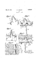
May 24, 1932. w. H. WILSON CLIP Filed Nov. 9, 1927 A TTORNE YS.
AV AV A 1 i y 5 CV 5% Patented May 24, l932 i a i V a v UN T S T S PAFT Y Q F CE H a l Hemmer nosnnentnsrcararoanm Application filed Noveinber '9, 1927. seria1 No. 2 32 ,1 2 2.
This invention relates generally to floor. Fig. 41: isa plan view of the metal'lath'se roof and wall constructionof the type 1n cured to a'support byImycli I I which concrete slabs are poured upon or re- F1g. "5 1s a vertical section of Fig.3 taken inforced by metal lath or other self=ce11ter ng on line -5 of Flg. 3, I 5 element which "in turn is supported. by steel I Correspond ng partsaredesignated by the supporting members; and more particularly Same reference characters 111 all the figures. I the invention relates to means for securing 1 My lnventioncomprlses a spring Qlip'des metal-lath or other self-centering elements to ignated generally as'l, which maybe formed joists, studding or other supports and for OI a slngle plece of stout w1re 2, whichis bent I anchoring the concrete to such element and V-shape at 3 subs ta11t1ally midway of its ends 60, support. 1 l r form, prlng V members 4' and 5, which The general object of the invention is to members are re'spectivelybent to form at their provide simple, eficient, inexpensive and im- QnClS a lock en'gagrng member 6 and a latch proved means for securing metal-lath'and the engag ng member the memberr t b fi t like toa support, and for embedding itself Q outwardlyatffi'atan obtuse angle and in the plaster and concrete which "is poured t altily at 9 substantially at'right anupon the metaHath, whereby the plaster, 'g f j 1 2k engaging member 6, concrete, lath and support are all effectively 31121 m rfi QII Ig firstbent w rd y tied to ether and a lateral reinforcement is t l0 E 1 g ndt w l'y at I I providgd for said support I ll and slightly in an outwardly curved d1rec-7 j A more particular object is to provide a Q 2 Q Q I 11? lat h engaglngmem 7 spring clip which may be inserted through II f I I metal lath and engaged with the lath sup- I n a, 2 to 5 21 U Q he drawlngs II portand which will embed itself in the conh %lconcrete 9 I t f,. 25 crete poured over the lath, for securing the constructl-on mcludmg the T l pp rt lath to the support and for anchoring the expanded mm 6 1 0 concrete to the lath and support.- 7 fi i 1 1 r I t at th b I 7 With the above objects in view, the inven- 7 n p y Yl VG Q 0 I e a ove con- I I 1 d usefur r'OVL crete-an d metal floor constructiomthe metal I 1 )0 non conslsts m the Dove an p th 16 s firt laced a alnst'the transverse sion, formation, construction, assoc ation and, .5, i d I g th I relative arrangement of parts, members and j d 911 11 7 1 5" 9% features all as shown in a certain em'bodimserte f Spaces' 90 t fim V ment in the accompanying drawings, delat the 9. engagmg mt q l er cribed enerall and more particularly: engaggd n? edge f the fi l ers I s 1 r ,fiange 18 of theT 1ron '15 and the curved porpomted out c gums tion 12 of the latch engaging member cammed I v li i l t l l s ec'tive view of a clip cml fih Qfli'er dgpfthe i Q- g 1 P 9 andthe V members 4 and 5 sprung apart I bodymg my mventlon' slightly until'thelatch engaging member 7 Q J 1 as Fig. 2 is a sectional view of .a metal lath firmly engages said Othr edgeofme iron i1 I and Support showing one of C11113.8 in the flan e 18 while the] Omens of t1'1e5cli"'beact of beln g lnserted through the lath and w n' -as 3 g nd engaged Wlfll the Support for Securmg the T11 engagthe outer side of the metal lathias 111th to PPP i shown. in Fig.- 3, thussecuringfandlocking r 3 is a 596151011311 716W i concret? a themetal lathftolsaid, T iron'flange 18; the
metal floor constructlonshowing my clip in- Concrete h 'p d e metalslath I I V I serted through the metal lath and engaged ["1 and my d p n thIIe-vcqncretg is thgnrfinal;
with the lath supportand showing the clip ;1 d Qe i th mj gmi g vt I anchored in the concrete whereby the lath, members 4: and 5 of the clip,fcovering theclip support and concrete are tied together. a I completely sothat the clip is firmlyembed- 1100 ded and anchored in the concrete 17 Whereby the metal lath 16, T iron support 15, and concrete 1? are firmly and effectively tied togetheiy My clip may be introduced through the metal lath between the ribs 20 and en gaged wi h the T iron'fiange 18 as indicated at 21 of Fig, 4:, or the clip may be bent at 22 and23 so as to straddle a rib 20 of the metal lath and to'engage with its members 6 and 7 the opposite edges of a T iron flange l8 at Opposite sides respectivelyrof said. rib as inicated at '24 of Fig. 4.
its full load'that it besuppoz ted laterally at frequent intervals against deflection, so that it cannot movein a sidewise direction. My invention accomplishes this purpose and could be used on steel'sections even if the lath is used ofholding the mctallath rigidly,
in position by attaching it to the steel supporting member at the same time furnishes a lateral support to said steel sup- I nortin member. VAs the connection is made if the sheets of lath lap on the supporting member than if the connection were at or near to t-hecent r of h upp rtin'g m e As 'fthe lath is not applied to thesupporting 4. In combination With a support, metal:
lath, and concrete or the like poured over sai metal lath, a spring clip formed With: a lock engaging member for engaging the lath and 7 one edge o sai pport, a lat e g g g member a apt d engage t e'l ha spring over andinto engagement with the other edge of said support, and an intermediate part-adapted to be embedded 1n said concrete. 1 It 1s necessary if a steel member 1s to carry e 5. In'combination with a support, metal lath, and concrete or the like poured over said metal lath, a spring clip bent between its nds in o a pair i sp i g -.members an a lock engaging member and a lath engaging m mber respectively at the ends of said spring m mb s, sa d engaging memb rs being vmiapted to be in erte h ugh said ath wi h said lock engaging member engagingsaid lath and one. edge ofsaid support, and said lath engaging. member engaging said lath an spr nging-i t engagement witht otheredge of sa d supp sa d ntermediate pen tion of the clip being embedded in the Concrete. Y 1 1 I v In e imony whereof, I ave signed my name to this specification,
WILLIAM WILsoN,
member until the lath is placed and His time to pour the concrete slab, there are no'proejections ell-the topofthe steel supporting member to cause difficulties in handling the member or inwalkingon it after it is in place- It is obvious that various changes, variat ers. and, m di tions y be ma in pr ticing the invent n, in dep r from the particular shoWing'oft-he drawings, without de arting. from 'the true spirit of the in- 'vention provide a lateralgstay for V 2; In combination, a metal lath, a support therefor, a covering for said metal-lath,fand imeans for securing saidmetal lath tofsaid support, sai m s b ng formed t a part anchored to said covering whereby said means provides a lateral stay for said supp rta r. f 3; In combination, a metal lath, .a support therefona covering; for said meta-llath, and
- lateral stay 'means ,for said support said mea s n ng eme ber having' a Par
Priority Applications (1)
| Application Number | Priority Date | Filing Date | Title |
|---|---|---|---|
| US232122A US1859946A (en) | 1927-11-09 | 1927-11-09 | Clip |
Applications Claiming Priority (1)
| Application Number | Priority Date | Filing Date | Title |
|---|---|---|---|
| US232122A US1859946A (en) | 1927-11-09 | 1927-11-09 | Clip |
Publications (1)
| Publication Number | Publication Date |
|---|---|
| US1859946A true US1859946A (en) | 1932-05-24 |
Family
ID=22871957
Family Applications (1)
| Application Number | Title | Priority Date | Filing Date |
|---|---|---|---|
| US232122A Expired - Lifetime US1859946A (en) | 1927-11-09 | 1927-11-09 | Clip |
Country Status (1)
| Country | Link |
|---|---|
| US (1) | US1859946A (en) |
Cited By (3)
| Publication number | Priority date | Publication date | Assignee | Title |
|---|---|---|---|---|
| US2711643A (en) * | 1951-02-24 | 1955-06-28 | Herbert H Robinson | Clip retained lath |
| US3193972A (en) * | 1961-03-20 | 1965-07-13 | Kenneth J Grove | Concrete flooring |
| US4819401A (en) * | 1988-04-08 | 1989-04-11 | Whitney Jr G Ward | Wire anchor for metal stud/brick veneer wall construction |
-
1927
- 1927-11-09 US US232122A patent/US1859946A/en not_active Expired - Lifetime
Cited By (3)
| Publication number | Priority date | Publication date | Assignee | Title |
|---|---|---|---|---|
| US2711643A (en) * | 1951-02-24 | 1955-06-28 | Herbert H Robinson | Clip retained lath |
| US3193972A (en) * | 1961-03-20 | 1965-07-13 | Kenneth J Grove | Concrete flooring |
| US4819401A (en) * | 1988-04-08 | 1989-04-11 | Whitney Jr G Ward | Wire anchor for metal stud/brick veneer wall construction |
Similar Documents
| Publication | Publication Date | Title |
|---|---|---|
| US5373676A (en) | Thin brick panel assembly | |
| US2898758A (en) | Anchor slot channel structure | |
| US2005030A (en) | Veneer fastening means | |
| US2129976A (en) | Clip and channel | |
| US3159251A (en) | Flexible corner molding for curved surfaces | |
| US2270672A (en) | Building slab | |
| US1555392A (en) | Combined floor covering and base strip | |
| US1246585A (en) | Fastening device. | |
| US2003996A (en) | Veneer wall construction | |
| US2272762A (en) | Base screed | |
| US1859946A (en) | Clip | |
| US4012159A (en) | Key-joint forming divider strip and screed for use with concrete slabs | |
| US1850961A (en) | Retaining means for building materials | |
| US1874790A (en) | Building material and retaining means therefor | |
| US1785790A (en) | Combination joist hanger and tie | |
| US2806290A (en) | Gage-line holder | |
| US2724960A (en) | Furred wall construction | |
| US2641035A (en) | Wall construction and clip therefor | |
| US2742778A (en) | Furring devices | |
| US2060274A (en) | Binding and dividing bar | |
| US2676553A (en) | Reglet | |
| US1969879A (en) | Structural insert | |
| US1342610A (en) | Sound-insulating device for building constructions | |
| US1751785A (en) | Screed holder | |
| US3997937A (en) | Carpet tack strip anchoring means and installation tool |