US1859942A - Plow - Google Patents
Plow Download PDFInfo
- Publication number
- US1859942A US1859942A US298197A US29819728A US1859942A US 1859942 A US1859942 A US 1859942A US 298197 A US298197 A US 298197A US 29819728 A US29819728 A US 29819728A US 1859942 A US1859942 A US 1859942A
- Authority
- US
- United States
- Prior art keywords
- wheel
- frame
- furrow
- carrying member
- lifting mechanism
- Prior art date
- Legal status (The legal status is an assumption and is not a legal conclusion. Google has not performed a legal analysis and makes no representation as to the accuracy of the status listed.)
- Expired - Lifetime
Links
Images


Classifications
-
- A—HUMAN NECESSITIES
- A01—AGRICULTURE; FORESTRY; ANIMAL HUSBANDRY; HUNTING; TRAPPING; FISHING
- A01B—SOIL WORKING IN AGRICULTURE OR FORESTRY; PARTS, DETAILS, OR ACCESSORIES OF AGRICULTURAL MACHINES OR IMPLEMENTS, IN GENERAL
- A01B63/00—Lifting or adjusting devices or arrangements for agricultural machines or implements
- A01B63/14—Lifting or adjusting devices or arrangements for agricultural machines or implements for implements drawn by animals or tractors
- A01B63/16—Lifting or adjusting devices or arrangements for agricultural machines or implements for implements drawn by animals or tractors with wheels adjustable relatively to the frame
- A01B63/166—Lifting or adjusting devices or arrangements for agricultural machines or implements for implements drawn by animals or tractors with wheels adjustable relatively to the frame manually adjustable
Definitions
- both ends of the frame be raised to approximately the same height and, accordingly, during this range of the opera ti on of the lifting mechanism, it is necessary that a large part of' the lifting motion be effective at the rear end of the frame to raise 19": this end up to approximately the same'height as the front end with the plows clear of the ground.
- he principal object of'the present invention is to provide improved lifting mecha-' nism which will have this characteristic operation.
- the differential relation between 'the lift at the front and rear ends is obtained by a certain link mounting of the-rear porti on of theframe on the rear furrow wheel,
- FIG. 4 is a fragmentary sectional view 1928.
- FIG. 1 Figure 3 is arsimilar view, illustrating the;
- Figure 4? is a simplified complementary View diagrammatically illustrating the relation of thepivots and links at such time;
- Q Figures 5' and 5* correspond to Figures 4: and it, except that they show lth'eklifti'ng' theplane of the line44 of Figure 1', showf V ing. the'position of .theparts at maximum mechanism actuated to one of its depth adjusting positions;
- Figures 6 and 6 are similar to the preceding figures, except that they show the lifting mechanism actuated to its transport position;
- Figure 7 is a fragmentary sectional View, illustrating the action of the adjusting means associated with the rear lifting mechanism
- Figure 8 is a fragmentary end view of the eccentric bushing through which this adjustment is effected;
- Figure 9 is a longitudinal sectional view through such bushing, taken on the plane of the line 9-9 of Figure 8;
- the frame of the plow is of any suitable construction, preferably comprising: two angle bars 14-14 which are bolt-ed at front and rear ends to bracket castings 15 and 16, respectively.
- plows represented by the disks 17, are sup ported on standards'18 which are secured be tween the Vertical flanges of the two frame bars 14'.
- the frame is supported on front and rear furrow wheels 19 and 21 and on a land wheel 22.
- land wheel has mounting on a frame extension comprising two bars 23 and 24 secured to brackets on the under sides of the beam bars 14 and extending laterally therefrom.
- Draft is transmitted tothe plow through adraft bar. 25 which is secured to and extends laterally from the front bracket casting 15, the outer endof said draft bar having bracing connection with one of the beam bars 14 through a brace bar 26.
- a coupling or hitch member 27 has horizontal swinging movement about a verticalpivot 28 carried by a clevis 29, and the latter has vertical swinging movement about a horizontal pivot 31 which is carried by. a bracket 32mounted on the draft bar 25.
- An adjustable steering link 33 is connected between the hitch member 27 and a steering arm 34 which extends from the front furrow wheel 19.
- the front end of the frame is raised and lowered with respect to the front furrow wheel 19 through the actuation of front lifting mechanism broadly designated 35.
- Such mechanism comprises a vertical wheel standard 36, a bell crank lever 37, and a link 38 which is pivotallyv connected between one arm ofsaid lever and the upper portion of.
- the front bracket casting 15 is formed with a long guide boss 39' which is mounted to slide up and down along 7 the vertical portion ofthe standard 36, the
- a long link, or bar44 which is pivotally connected at 43 to the inner arm 37' of the bell crank lever extends back to the rear lift-- ing mechanism and functions as a motion transmitting device for actuating the front lifting mechanism 35, as will hereinafter appear. ably connected to the arm 37 to aid in lifting the plow.
- the mechanism for lifting the frame relatively to the land wheel 22 is generally indicated at 45 in Figures 1, 2 and 3, and shown as being of the manually operated type, although it will be understood that power lift mechanism maybe associated with this wheel and operatively connected with the front and rear liftmechanisms when a power lift'is desired.
- the land wheel is journaled on the spindle end of a crank axle 46 which has bearing support for swinging movement in a bearing block 17 secured between the extension frame bars 23 and24.
- An operating lever 48 is secured to the bearing portion of the axle and has braced connection with the crank portion thereof through a bracing link 49.
- Such lever car ries the usual detent latch for engaging in the notched sector 51 which is rigidly securedto the stationary bearing block 47.
- a counterbalancing spring 40 is suitlever 48 is within convenient reach of the operators position on the seat 52 at the rear end of the plow, and by-:moving such lever in one direction or the other-the land side of the formed integral with and extending down-- wardly from the inner end of the horlzontal which is designated 54 in its entirety, it will be seen from Figures 4, 5'and 6 that the rear bracket casting 16 is formed with a long bearing; boss 55 at its rear end, which bearin boss extends transversely of the frame, said casting being also formed with a bearing boss 56 at its front end disposed. in a plane below the boss 55.
- Such member serves to mount. the rear furrow wheel '21 on As shown in Figure 1, such member is dis posed the furrowward side of the bracket casting l6, and comprises a long horizontally extending boss 59 through which the offset swinging end 57 of the crank 57 extends.
- Such wheel carrylng member also comprises a substantially vertically extendlng boss 59* boss 59. Pivotally mounted in the upright bent spindle portion 61 on which the furrow wheel 21 isjournalled.
- the furrowward end 57 of the crank or roclrshaft 57 passes rotatably through the boss 59 of the wheel carrying memberand has asquared projecting end to which is rigidly secured an actuating member 62 in the form of a manually operating lever.
- sector 63 is secured to a flangefie which project-s upwardly from the end of the boss '59, whereby the sector constitutes a rigid'part of the wheel carrying member 59.
- the act-uating lever 62 is provided with the usual latch mechanism 65 for engaging in the sector 63 and holding the lift mechanism inany desired position.
- the motion transmitting link 44 which extends rearwardly from the front lift mechanlsm 35 is pivotally connected to the actuating lever 62 at' a pivot 66; It will be seen from the foregoing that the actuating lever'62 constitutes a rigid, part of the crank and that forward motion imparted to said lever willswing the crank te'nding'to force the pivot axis-57 downwardly and to force:
- the rear end of the link 58 has a laterally bent pivot end 58 which is pivotally connected to the lower portion of the wheel carrying" member 59, ata point approximately directly below the pivot axis 57 nec'tion between the link andthe wheel carrying member is adjustable, as best shown in Such pivotal co n- Figures 8 and 9, from which it-will be seen that the-lower portion of the vertical'bo ss 59 o'f the wheel carrying member is'formed', with a horizontal boss 68 'in which a bearing bushing or sleeve 69 is rotatably mounted.
- pivotaxis 58 can be shifted towards or away from the wheel carrylng member, thuspro ducing the effect of increasing or decreasing the effective length of the link 58.
- the eccentric bushing is held in any desired angle ofadjustment by a bolt 71 which passes one of a series of radial slots 73 formed in. a collar 74 atthe end ofthe adjustable bushing.
- the bushing may through a flange 2 on the end of the boss 69 v r and is adapted to engage selectivelyin any beturned by applying a wrench to the squared i projection 75 extending from the end of the bushing, whereupon the boltis replaced in the adjacent one of the notches 73to hold the lmshing in the desired adjustment.
- the purpose ofthi's' adjustment is to properly position the heightof the rear furrow wheel 21 with respect to the plowdisks 17 when the plow is in working positiom in order to compensate for different sizes of disks, wear of d1sks,etc.
- a flange 77 extending rearwardly from th wheel carrying member 59 has a: seat bar78;
- whi clrthc seat 52 is mounted on the rear end of whi clrthc seat 52 is mounted. It will be noted that the seat is disposed at a point in rear of theaxis ofthe rear'furrow wheel 21 so that when the plowis belng raised to transport. 'poslt on,
- V r I I j Suitable lock mechanism 79 may be provided on the wheel carrying member59 to control; the caster movement of the axle 61 relatively thereto, the details of whichlock mechanism constitute no part of the present invention, It will suffice-to say that in its preferred embodiment suchl'ock mechanism holds the rear furrow wheel in definiteworking posit-ion for straightaway plowing, per- I mitting the wheel to caster automatically, however, when the implement is turning to the left.
- the lock When turning to the right, the lock may be released by a suitable foot pedal 81 so as to permit the wheel to follow the turn.
- a suitable foot pedal 81 When turning to the right, the lock may be released by a suitable foot pedal 81 so as to permit the wheel to follow the turn.
- the operation of the lift mechanism Wlll be best understood by reference to Figures 4, 5 and 6 and to their complementary Figures l 5 and 6 which diagrammatically illustrate the three positions illustrated in the first mentioned figures.
- crank 57 together with the actuating lever 62 constitute a rigid operat ing member through which lifting motlon 1s made effective between the wheel carrying member 59 and the frame.
- the crank portion 57 of such operatingrmember functions as a link for governing the movement of the upper end of the wheel carrying member, it heingnoted that the pivot axis 57 between this link and the frame is disposed at a point approximately in rear of the wheel carrying member.
- Tlieother link 58 constitutes a control link for governingthe translational and oscillatory movement of the wheel carrying mem-,
- pivot axis 58 between such link and the wheel carrying member is dlSPOSGCl approximately directly below the upper pivot axis 57 and that the pivot axis 58 between this control link and the frame is disposed at a point in front of the wheel carrying member.
- crank 57;and link 58 form two oppositely mounted swinging links having their adjacent ends pivotally connected with the wheelcarrying member and having their opposite ends pivotally connected with the frame.
- the adjacent ends swing through opposite arcs that intersect a line extending between the pivot centers of the opposite ends of the links.
- Figures 4: and e represent the position of theflifting mechanism when the plow is lowered to a maximum'depth of plowing. It will be noted that, in this position, thertwo links 57' and 58 are disposed approximately onlines extending down through the center.
- the lever 62 is thrust forwardly a short distance, which movement of the pivot 66 acting through the most effective part of its arc, transmits mo- 7 tion through the link 14: to the bell crank lever 37, the two arms of which are also in positions effective to transmit rapid motion to the front endof'the frame.
- the vertical displacement between the wheel carrying member and the frame is causing the control link'58 to swing in a clockwise direction, which draws the pivot 58* forwardly and hence swings the lower end of the wheel carrying member forwardly in a clockwise direction.
- the wheel carrying member has an oscillatory or rotative move ment set up therein in a direction operating to swing the rear furrow wheel 21 forwardly under the frame. Vith such motion, the long rearwardly extending portion 61 of the axle becomes effective as a crank for forcing the rear end of the frame upwardly.
- front end of the frame is still being raised through continued actuation'of the front lifting mechanism 35, but the. front end of the frame is not rising as rapidly as the rear end.
- Such bearing bushing in the oppositedirectiomthe' wheel I carrying member can be swung backwardly to raise the furrow wheel slightly relatively to the disks'
- Such bearing bushing may be given different-settings to impose the weight of therear furrow wheelon theplow ele merits, or to control thedepth ofpenetration of the rear plow element, and may be utilized to ad ust the implementto-diiferent soil con;
- said rear lifting mechanism comprising awheel carrying member for said rear furrow wheel, a pair of oppositely mounted swinging links having their adjacent ends pivt- 'ally connected with said wheel carrying 7 for raising and lowering the rear portion of said frame relatively to said rear furrow wheel, means operatively connecting said lifting mechanisms, said means including a member pivotally connected to both the front lifting mechanism and the rear lifting mechanism, said rear lifting mechanism compr1sing a wheel carrying member for said rear furrow wheel, a link pivotally connected with said wheel carrying member and extending forwardly for pivotal connection with said frame, a second link pivotally connected with said wheel carrying member and eX- tending rearwardly for pivotal connection with saidframe, said linksextending in 0pposite but Vrearwardly converging directi'ons when theframe is substantially in its lowermost position, and means for actuatingsaid lifting mechanisms.
- a wheeled gang plow the combina tion of a frame, a plurality of plows carried by said frame, front and rear furrow wheels and 'a land wheel supporting said frame, front lifting mechanism for raising and lowering the front portion of said frame relatively to said front furrow wheel, rear lifting mechanism for raising and lowering the rear portion of said frame relatively to said rear furrow wheel, connecting means pivotally connected to each of said two lifting mechanisms, said rear lift-ing mechanism comprising a wheel carrying member for'said rear furrow wheel, a pair of oppositely mounted swinging links having their inner ends pivot ally connected with said wheel carrying member on vertically spaced centers and their outer ends pivotally connected with said frame, said linksbeing so angularly related that they are adapted to move through a position of substantial parallelism and are not operative to raise the rear end of the frame any substantial amount'during the initial swinging movement of the links until said links have passed their parallel position, and actuating means for operating said lifting mechanisms and including a lever connected to one of said
- a wheeled gang plow the combination of a frame, a plurality of plow elements carried thereby,front and rear furrow wheels and a land wheel supporting said frame, front lifting mechanism for raising and lowering the front portion of said frame relatively to said front furrow wheel, rear lifting mechanism for ra sing and lowering tlie rear portion of said frame relatively tosaid rear furrow wheel, connecting means extending be tween said front and rear lifting mechanisms, said rear lifting mechanism comprising a wheel carrying member for said rear furrow wheel, a pair of links movably connecting said wheel carrying member with said frame, said links swinging about pivot centers arranged whereby in normal operating position said l nksextend substantially in parallelism, and thereafter said links extend at a pronounced angle to each other, and actuating means for operating said lifting mechauisms.
- a wheeled plow the combination of a frame, furrow opening means carried thereby, front and rear furrow wheels supporting said frame, front lifting mechanism for raising and lowering the front portion of said frame relatively to said front furrow wheel, rear lifting mechanism for raising and lowering the rear portion of said frame relatively to said rear furrow wheel, said-rear lifting mechanism comprising a wheel carrying member, an.
- a wheeled plow the combination of a frame, furrow opening means carried there by, front and rear furrow wheels supporting said frame, front lifting mechanism for raising and lowering the front portion of said frame relatively to said front furrow wheel, rear lifting mechanism for raising and lowering the rear portion of said frame relatively to said rear furrow-wheel, connecting means operatively connecting said lifting mechaing a wheel carrying member for said rear furrow wheel, oppositely mounted swinging links connecting said wheel carrying member with said frame, actuating means for operating said rear lifting mechanism, and means cooperating with one of said links and adapted to change the angular relation be tween one of said links and said wheel carrying member for relatively adjusting said rear furrow wheel and frame independently of said actuating means.
- a Wheeled plow the combination of a frame, furrow opening means carried thereby, frontand rear furrow wheels supporting said frame, front lifting mechanism for raising andlowering the front portion of said frame relatively to said front furrow wheel, rear lifting mechanism for raising and lowering the rear portion of said frame relatively to said rear furrow wheel, connecting means operatively connecting said lifting mechanisms, said rear lifting mechanism comprising a wheel carrying member for said rear furrow wheel, oppositely mounted swinging links connecting saidwheel carrying member with said frame, an actuating member for operating saidrear lifting mechanism, and means cooperating with one of said links and operative toincrease or descrease the effective length thereof for adjusting said rear furrow wheel and frame independently of the operation of saidactuating member.
- a wheeled plow the combination of a frame, furrow opening means carried thereby, front and rear furrow wheels supporting said frame, front lifting mechanism for raising and lowering the front portion of said frame relatively to said front furrow wheel, rear lifting mechanism for raising and-lowering the rear portion of said frame relatively to said rear furrow wheel, connecting means operatively connecting said lifting mechanisms, said rear lifting mechanism comprising a wheel carrying member for said rear furrow wheel, oppositely mounted swinging links connecting said wheel carrying member with said frame, an actuating member for operating said rear lifting mechanism, and an adjustable eccentric hearing for one of said links operative to relatively adjust said rear furrow wheel and frame independently of the operation of said actus ating member.
- a wheeled gang plow In a wheeled gang plow, the combination of a frame, a plurality of furrow openers carried thereby, front and rear furrow Wheels supporting said frame, front lifting mechanism for raising and lowering the front portion of said frame relatively to said front furrow wheel, rear lifting mechanism for raising and lowering the rear portion of said frame relatively to said rear furrow wheel, said rear lifting mechanism comprising a wheel carrying member having a rearwardly extending axle on which the rear furrow wheel is mounted, an upper link pivotally connected at its front end with said wheel carryingmember and pivotally mounted at its rear end of said frame, a lower link pivotally connected at its rear end withsaid wheel carrying member and pivotally mounted at its front end on said frame, an actuating lever extending from one of said links, motion transmitting means connecting said actuating lever wlth said front lifting mechanism, and an eccentric bearing bushing inter 1 posed between the rear end of saidlower link and said wheel carrying member for adjusts ing the rear furrow wheel relative to said furrow
- a wheeled plow In a wheeled plow, the combination of a frame, furrow opening meanscarried there by, front and rear furrow wheels supporting said frame, and lifting mechanismfor raising and lowering said frame relatively to said wheels comprising means for causing substantially vertical translational motion of slight magnitude between saidrear fur-J row wheel and said frame during the depth adjusting range of said lift mechanism and for thereafter causing a forward swinging motioniof said rear furrow wheel relative .to said frame for rapidly raising said frame to transport position, said front and rearjfur row wheels THOVlIlg substantially the same amount relative to the frame. 7 r
- a wheeled plow the combination of a frame, a plurality of plow disks carried thereby, front and rear furrow wheels and a land wheel supporting said frame, front lift ing mechanism for raisingand lowering the front portion of said frame relatively to said front furrow wheel, means for steering said front furrow wheel, lifting mechanism coopcrating with said land wheel for raising the land side of said frame relatively to said land wheel, rear lifting mechanism for raising andlowering the rear portion of said frame relatively to said rear furrow wheel, said rear lifting mechanism comprising a wheel carrying member, an.
- a wheeled plow the combination of a frame, furrow opening means carried thereby, front andrear furrow wheels supporting said frame, front lifting mechanism for raising and lowering the front portion of said frame relatively to said front furrow wheel, rear lifting mechanism for raising and lowering the rear portion of said frame relatively to said rear furrow wheel, connecting means operatively connecting-said lifting mechanisms, said rear lifting mechanism comprising a'wheel carrying member for said rear furrow, wheel, oppositely mounted swinging links connecting said wheel carrying member with said frame, ac-
- a wheeled plow the combination of a frame, furrow opening means carried thereby, front and rear furrow wheels supporting said frame, front lifting mechanism for raising and lowering the front portion of said frame relatively to said front furrow wheel, rear lifting mechanism for raising and lowering the rear portion of the frame relatively to said rear furrow wheel, said rear.lifting mechanism comprising a member carrying said rear furrow :wheel, a pair of oppositely 'mounted swinging links connecting said wheel carrying member with said frame, said linksbeing mounted in such angular relation that initial movement of the links imparts a forward tipping of the upper part of said :member relative to-the lower part, and means for actuatingsaid lifting mechanisms.
- a wheeled plow the combination of a frame, furrow opening means carried thereby, front and rear furrow wheels supporting said frame, front lifting mechanism for raising and lowering the front portion of said frame relativelyto said front furrow wheel, rear lifting mechanism' for raising and lowering the rear portion of the frame relatively to said rear furrow wheel, said .rear'lifting mechanism compris ng a member carrying said rear furrow wheel, a pair of oppositely mounted swinging links connecting said wheel carrying member with said frame, said links being mounted in'such angular relation that initial movement of the links imparts a rearward tipping of the lower part of said member relative to the up; per part, and means for actuating said lift? ing mechanisms.
- a frame,furrow opening means carried there by a rear furrow wheel supporting said frame, rear lifting mechanism for raising and lowering the rear portion of the frame relatively to said rear furrow wheel, said rear lifting mechanism comprising a mem ber carrying said rear furrow wheel, a pair of swinging links connecting saidwheel carrying member with said frame, and means for actuating said liftingmechanism com ⁇ prising a lever pivotally connectedwith the wheel carrying member and a cooperating sector carried bysaid wheel, carrying member.
- a wheeled plow In a wheeled plow, the combination of a frame, furrow'open'ing means carried thereby, a rear furrow wheel supporting said frame, rear lifting mechanism for raising and lowering the rear portion of the frame relatively to said rear furrow wheel, said rear lifting mechanism comprising a member carrying said rear furrow wheel, a pair of oppositely mounted swinging links con' necting said wheel carrying member with said frame, and means for actuating said lifting mechanism comprising a lever pivotally connected with the wheel carrying mem-' ber and rigidly connected with one of said oppositely mounted links.
- a wheeledYplow the combination of a frame, a plurality of furrow openers carried thereby, means including a rear furrow wheel and a land wheel'supporting said frame, rear lifting mechanism for raising and lowering the rear portion of said frame relatively to said rear furrow wheel comprising a wheel carrying member for said rear furrow wheel, a link pivotally connected with said wheel carrying member and extending forwardly for pivotal connection with said frame, a second link pivotally connected with said wheel carrying member and extending rearwardly for pivotal connection with said frame, said links extendingin op: posite but rearwardly converging directions when the frame is in its lowermost position, and means for actuating said lifting mechanism.
- a frame furrow opening means carried thereby, means including a rear furrow wheel for supporting said frame, rear lifting mechanism for raising and lowering the rear portion of said frame relatively to said rear furrow wheel, said rear lifting mechanism comprising a wheel carrying member, an axle swiveled in said member and extendingrearwardly therefrom, said rear furrow wheel being mounted on said axle, a crank having its front end pivotally connected with the upper portion of said wheel carrying member and having its rear end pivotally connected with said frame, and a link having its rear end pivotally connected with said wheel carrying member and its front end pivotally connected with said frame, the angular relationof said crank V and link being such that the upper portion of said wheel carrying member has a component of movement which is forward with respect to the lower pivotal connectiondu'ring the initial part of the lifting operation.
- a wheeled plow the combination of a frame, furrow opening means carried themby,means including a rearfurrow wheelfor supporting said frame, rear lifting mecha nism for raising and lowering the rear portion of said frame relatively to said rear furrow wheel comprising a wheel carrying member for said rear furrow wheel, a pair of swinging links connecting said wheel carrying member with said frame, actuating means for operating said rear lifting mechanism, and means cooperating with one of said links and adapted to change the angular relation between one of said links and said wheel carrying member for relatively adjusting said of said actuating means.
- rear furrow wheel and frame independently M for raising and lowering 'the rear portion of said frame relatively to said rear furrow wheel comprising a wheel carrying member for saidrear furrow wheel, a pair of swinging links connecting said wheel carrying member with said frame, an actuating member for operating said rear lifting mechanism,
- a wheeledplow In a wheeledplow, the combination of frame, at least one plow carried a by said frame, supporting means for said frame including a rear furrow wheel, and means for adjusting the position of said rear wheel relative to the frame, said means comprising pivoted upper and lower links oppositely mount-i ed, a rear wheel carrying member carried by f the links, the upper link being shorter than the lowerlink, and means for. swinging-one of the links toraise and lower the frame, said linksbeing so angularly arranged that initial raising movement ofthe frame from its lowermost position is relatively slow andsubsequent raising movement is relativelyjrapid.
Landscapes
- Life Sciences & Earth Sciences (AREA)
- Zoology (AREA)
- Engineering & Computer Science (AREA)
- Mechanical Engineering (AREA)
- Soil Sciences (AREA)
- Environmental Sciences (AREA)
- Soil Working Implements (AREA)
- Agricultural Machines (AREA)
Description
May 24, 1932- c. G. STRANDLUND PLOW Filed Aug. 8, 1928 4 Sheets-Sheet l W/TNESS y 1932. c. G. STRANDLUND 1,859,942
PLOW
Filed'Aug. 8, 1928 4 Sheets-Sheet 2 FIE-3 May 24, 1932. c. e. STRANDLUND PLOW Filed Aug. 8, 1.928 4 SheetsSheet 3 5 3 mm eh a E w... ,f @n
W/T/VESS May 24, 1932- c. G. STRANDLUND PLOW Filed Aug. 8, 1928 4 Sheets-Sheet 4 Patented May 24, 1932 PATE CARL G. STRANDLUND, 0F MOLINE, ILLINoIs'A-ssIGNoR To DnE'REa oo PANY; 0E I MoLINE, ILLINOIS, A CORPORATION or ILLINOIS rLow Applioation'filed August 8,
15' because it is the height of adjustment of the frame relatively to the front furrow wheel that determines the depth ofplowing... As is well known, the depth of the furrows cut by the plows determines the depth at which 5153 the rear furrow wheel runs, and hence this. 7 rear wheel cannot ordinarily serveas a gauge element for determiningthe depth adjustment, 1 j
'It therefore follows that in effecting a depth adjustment, a differential relation must be maintained between the liftefi'ective atthe front and rear ends ofthe frame, that isto say, the major portion of the lifting or lowering motion must be'eifective at the front t l end of the framewith verylittle, if any, of
this lifting or lowering motion effective ,at' the rear end of the frame. However, when the plows are lifted to transport position, it
is desirablethat both ends of the frame be raised to approximately the same height and, accordingly, during this range of the opera ti on of the lifting mechanism, it is necessary that a large part of' the lifting motion be effective at the rear end of the frame to raise 19": this end up to approximately the same'height as the front end with the plows clear of the ground. a V
he principal object of'the present invention is to provide improved lifting mecha-' nism which will have this characteristic operation. The differential relation between 'the lift at the front and rear ends is obtained by a certain link mounting of the-rear porti on of theframe on the rear furrow wheel,
' whereby a progressively accelerated lifting:
embodiment a lifting mechanism in a position for decreasj 90 Figure 4 is a fragmentary sectional view 1928. Serial No.298 ;197.
motion occurs between: this portion ofotlie' frame and the Wheel. During the, depth ad time, to the lifting mechanism at the front@ end of theframe. During that part of the range of actuation for raising the plow to! transport position, the rear furrow flwheel is= caused to oscillate forw ardly.,-at a rapidly. increasing rate so that the rearwardly ex tending axle on which saidwheel'is mounted operates as a lifting crank for quickly raising the rear end of the frameto transport larger or smaller disks, anddilferent soil conditions. This adjusting means is" preferably arranged to'vary the effective length" or to shift the pivot center of'one of the linkswhich governs the oscillatory movement of the rear furrow wheel.
Other objects and advantages of the in vention will appearin the followingdescri'ption of a preferred: embodiment thereof; In
the accompanying drawingsillustrating such,
Figure 1 is a plan Figure'Q is a sideelevational view=thereo1f, illustrating the lifting mechanism inthe posi-' tion of maximunrplowing depth;
view of the present plow 1 Figure 3 is arsimilar view, illustrating the;
ing the plowing depth;
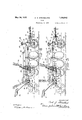
through the rear liftfmechanism taken on plowing depth, and Figure 4? is a simplified complementary View diagrammatically illustrating the relation of thepivots and links at such time; Q Figures 5' and 5* correspond to Figures 4: and it, except that they show lth'eklifti'ng' theplane of the line44 of Figure 1', showf V ing. the'position of .theparts at maximum mechanism actuated to one of its depth adjusting positions;
Figures 6 and 6 are similar to the preceding figures, except that they show the lifting mechanism actuated to its transport position;
Figure 7 is a fragmentary sectional View, illustrating the action of the adjusting means associated with the rear lifting mechanism Figure 8 is a fragmentary end view of the eccentric bushing through which this adjustment is effected; and
Figure 9 is a longitudinal sectional view through such bushing, taken on the plane of the line 9-9 of Figure 8;
Referring to Figure 1, the frame of the plow is of any suitable construction, preferably comprising: two angle bars 14-14 which are bolt-ed at front and rear ends to bracket castings 15 and 16, respectively. The
plows, represented by the disks 17, are sup ported on standards'18 which are secured be tween the Vertical flanges of the two frame bars 14'. The frame is supported on front and rear furrow wheels 19 and 21 and on a land wheel 22. Such land wheel has mounting on a frame extension comprising two bars 23 and 24 secured to brackets on the under sides of the beam bars 14 and extending laterally therefrom.
Draft is transmitted tothe plow through adraft bar. 25 which is secured to and extends laterally from the front bracket casting 15, the outer endof said draft bar having bracing connection with one of the beam bars 14 through a brace bar 26.
A coupling or hitch member 27 has horizontal swinging movement about a verticalpivot 28 carried by a clevis 29, and the latter has vertical swinging movement about a horizontal pivot 31 which is carried by. a bracket 32mounted on the draft bar 25. An adjustable steering link 33 is connected between the hitch member 27 and a steering arm 34 which extends from the front furrow wheel 19.
Referring to Figures 2 and 3, the front end of the frame is raised and lowered with respect to the front furrow wheel 19 through the actuation of front lifting mechanism broadly designated 35. I
Such mechanism comprises a vertical wheel standard 36, a bell crank lever 37, and a link 38 which is pivotallyv connected between one arm ofsaid lever and the upper portion of.
the wheel standard. The front bracket casting 15 is formed with a long guide boss 39' which is mounted to slide up and down along 7 the vertical portion ofthe standard 36, the
standard also being free to swivel in the boss wardly inclined spindle end 36 of the wheel standard (Flgure 1), and the steering arm 34 1S suitably secured to this lower portion 3' of the wheel standard to revolve the same The bell crank lever ing bracket 41 which is bolted to the under sides ofthe frame bars 14. The outer arm 37 of the lever is pivotally connected to the lower end of the link 38, the upper end thereof being pivotally connected to a collar 42 which is mounted on the wheel standard'36.
The construction and mounting of-this collar is old and well known, being such that the collar cannot slide vertically on the stand ard, but the standard is free to swivel inthe collar. Referring to Figure 2, it will be seen that when the inner arm 37 of the bell crank lever is allowed to swing rearwardly, the, 7
front end of the frame is permitted to slide down along the wheel standard .36 to lower the plows into the ground'and, referring to Figure 3, it will be seen that when this lever arm 37 is thrust forwardly, the opposite arm 37 exerts a downward pull on the'link 38 and standard 36 which, reacting throughthe bearings 41,-results in the front portion of the frame being raised upwardly along the standard for lifting the plows relatively to the'ground.
A long link, or bar44 which is pivotally connected at 43 to the inner arm 37' of the bell crank lever extends back to the rear lift-- ing mechanism and functions as a motion transmitting device for actuating the front lifting mechanism 35, as will hereinafter appear. ably connected to the arm 37 to aid in lifting the plow. p I J v The mechanism for lifting the frame relatively to the land wheel 22 is generally indicated at 45 in Figures 1, 2 and 3, and shown as being of the manually operated type, although it will be understood that power lift mechanism maybe associated with this wheel and operatively connected with the front and rear liftmechanisms when a power lift'is desired. In the embodiment shown,.the land wheel is journaled on the spindle end of a crank axle 46 which has bearing support for swinging movement in a bearing block 17 secured between the extension frame bars 23 and24. l 7
An operating lever 48 is secured to the bearing portion of the axle and has braced connection with the crank portion thereof through a bracing link 49. Such lever car ries the usual detent latch for engaging in the notched sector 51 which is rigidly securedto the stationary bearing block 47. The.
A counterbalancing spring 40 is suitlever 48 is within convenient reach of the operators position on the seat 52 at the rear end of the plow, and by-:moving such lever in one direction or the other-the land side of the formed integral with and extending down-- wardly from the inner end of the horlzontal which is designated 54 in its entirety, it will be seen from Figures 4, 5'and 6 that the rear bracket casting 16 is formed with a long bearing; boss 55 at its rear end, which bearin boss extends transversely of the frame, said casting being also formed with a bearing boss 56 at its front end disposed. in a plane below the boss 55. These two bosses define pivot centers which'remain in fixed=relation to the frame and relatively to which the rear furrow wheel 21 swings in the operation of the lifting mechanism. Acrank 57. is journalled for swinging movement in the boss 55, and a link 58 has its front end pivotally mounted for rotative movement in the other boss 56. The crank is held against endwise movement in'the boss 55 by a collar which is detachably-secured to the crank at the end of thebo'ss (Figure l). Pivot-ally connected between the swinging ends of the crank 5'7 and link 58 is a casting59 which functions as a wheel carrying member that is to say, it
serves to mount. the rear furrow wheel '21 on As shown in Figure 1, such member is dis posed the furrowward side of the bracket casting l6, and comprises a long horizontally extending boss 59 through which the offset swinging end 57 of the crank 57 extends. Such wheel carrylng member also comprises a substantially vertically extendlng boss 59* boss 59. Pivotally mounted in the upright bent spindle portion 61 on which the furrow wheel 21 isjournalled.
The furrowward end 57 of the crank or roclrshaft 57 passes rotatably through the boss 59 of the wheel carrying memberand has asquared projecting end to which is rigidly secured an actuating member 62 in the form of a manually operating lever. sector 63 is secured to a flangefie which project-s upwardly from the end of the boss '59, whereby the sector constitutes a rigid'part of the wheel carrying member 59. The act-uating lever 62 is provided with the usual latch mechanism 65 for engaging in the sector 63 and holding the lift mechanism inany desired position. The motion transmitting link 44: which extends rearwardly from the front lift mechanlsm 35 is pivotally connected to the actuating lever 62 at' a pivot 66; It will be seen from the foregoing that the actuating lever'62 constitutes a rigid, part of the crank and that forward motion imparted to said lever willswing the crank te'nding'to force the pivot axis-57 downwardly and to force:
A latching the other axis'5'l' upwardly, which effects the raising of the rear end of the plow frame, as i will be presently described. U Such raising of the rear end ofthe plow frame is aided by a counterbalancing spring 60 which pulls forwardly on-an arm ex: tending upwardly from the'land endof the crank 57 see Figure 1.
The rear end of the link 58 has a laterally bent pivot end 58 which is pivotally connected to the lower portion of the wheel carrying" member 59, ata point approximately directly below the pivot axis 57 nec'tion between the link andthe wheel carrying member is adjustable, as best shown in Such pivotal co n- Figures 8 and 9, from which it-will be seen that the-lower portion of the vertical'bo ss 59 o'f the wheel carrying member is'formed', with a horizontal boss 68 'in which a bearing bushing or sleeve 69 is rotatably mounted.
, The pivot end 58 of the link passes through this bushing,eccentricallythereof, and it will be evident that by rotating the bushing, the
A flange 77 extending rearwardly from th wheel carrying member 59 has a: seat bar78;
secured thereto, on the rear end of whi clrthc seat 52 is mounted. It will be noted that the seat is disposed at a point in rear of theaxis ofthe rear'furrow wheel 21 so that when the plowis belng raised to transport. 'poslt on,
the weightof the operator on the seat is ef fectlve through a lever arm tending to 'swmg saidrear wheel'forwardly under theframe in a direction tending to aid inlifting the plow. V r I I j Suitable lock mechanism 79 may be provided on the wheel carrying member59 to control; the caster movement of the axle 61 relatively thereto, the details of whichlock mechanism constitute no part of the present invention, It will suffice-to say that in its preferred embodiment suchl'ock mechanism holds the rear furrow wheel in definiteworking posit-ion for straightaway plowing, per- I mitting the wheel to caster automatically, however, when the implement is turning to the left. When turning to the right, the lock may be released by a suitable foot pedal 81 so as to permit the wheel to follow the turn. The operation of the lift mechanism Wlll be best understood by reference to Figures 4, 5 and 6 and to their complementary Figures l 5 and 6 which diagrammatically illustrate the three positions illustrated in the first mentioned figures. It will be observed that,the' crank 57 together with the actuating lever 62 constitute a rigid operat ing member through which lifting motlon 1s made effective between the wheel carrying member 59 and the frame.- The crank portion 57 of such operatingrmember functions as a link for governing the movement of the upper end of the wheel carrying member, it heingnoted that the pivot axis 57 between this link and the frame is disposed at a point approximately in rear of the wheel carrying member. r V
' ber, it being noted that the pivot axis 58 between such link and the wheel carrying memberis dlSPOSGCl approximately directly below the upper pivot axis 57 and that the pivot axis 58 between this control link and the frame is disposed at a point in front of the wheel carrying member.
Thus, the crank 57;and link 58 form two oppositely mounted swinging links having their adjacent ends pivotally connected with the wheelcarrying member and having their opposite ends pivotally connected with the frame. The adjacent ends swing through opposite arcs that intersect a line extending between the pivot centers of the opposite ends of the links.
Figures 4: and e represent the position of theflifting mechanism when the plow is lowered to a maximum'depth of plowing. It will be noted that, in this position, thertwo links 57' and 58 are disposed approximately onlines extending down through the center.
of the rear furrow wheel, which takes some of the stress off the lever 62. At this time, the front lift mechanism 35 is in the position illustrated in Figure 2, with the front end ofthe plow frame lowered to a position of maximum plowing depth along the wheel standard 36, the frame then being substantially level with the ground. 7
To reduce the depth of plowing the lever 62 is thrust forwardly a short distance, which movement of the pivot 66 acting through the most effective part of its arc, transmits mo- 7 tion through the link 14: to the bell crank lever 37, the two arms of which are also in positions effective to transmit rapid motion to the front endof'the frame.
Hence, themotion of the actuating lever 62 through its depth adjusting range, represented by the first fouror five notches 63 1n the sector 63, produces a rapid rise of the front end of the plow frame along the wheel standard 36, as illustrated in Figure 3. This 4 same depth adjusting motion of the lever 62 has very little effect for raising the rearend of the lever over the first few notches tends to swing the pivot center 57"" downwardly, actually resulting in the pivot center-57 rising slightly.
This tends to move the upper end of the wheel-carrying member 59 forwardly to a slight extent relatively to the frame. However, the other link 58 in swinging downwardly at the center 58 or upwardly at the center 58 also tends to move the lower portion of the wheel carrying member forwardly. Thus, there .is a slight vertical translational motion between the frame'and the wheel carrying member, and also a slight horizontal translational or shifting motion between these two parts, but there is no appreciable oscillation or forward swinging of the wheel carrying member under the frame. Hence, during this initial depth adjusting motion of the lever 62, the rear end of the frame is only elevated a comparatively short distancev relatively to the rear furrow wheel 21, much less in degree than the elevationof the front end of the frame relatively to the front fur.- row' wheel. It will be noted that-in the position shownin Figure 4, or in moving from the'position of Figure into the position. of Figure 5, the two links 57 and 58 assume positions in substantial parallelism.
Continued forward motion of the actuatinglever 62, beyond the first few notches I in sector 63 represents that range of lift for raising the implement to transport position v forbringing the plows up out ofthe ground. During this range of movement, the wheel ca rying member 59 is given an oscillatory or forward swinging movement whereby the rear furrow wheel 21 is carried forwardly tion of the actuating lever 62, the further downward movement of the pivot center 57 or upward movement of the pivot center 57 will continue the vertical translatory movement between the wheel carrying member and the frame, but in addition thereto will i I cause the upper end of the wheel carrying" member .(the pivot center 57 to swing rearint 1-; moved forwardly to'approximately the last' wardly relatively to the frame in a counterclockwise direction.
At the same time, the vertical displacement between the wheel carrying member and the frame is causing the control link'58 to swing in a clockwise direction, which draws the pivot 58* forwardly and hence swings the lower end of the wheel carrying member forwardly in a clockwise direction. Thus, with the upper end of the wheel carrying member being swung rearwardly and the lower end being swung forwardly, the wheel carrying member has an oscillatory or rotative move ment set up therein in a direction operating to swing the rear furrow wheel 21 forwardly under the frame. Vith such motion, the long rearwardly extending portion 61 of the axle becomes effective as a crank for forcing the rear end of the frame upwardly. The oscillatory or rotative movement of the wheel carrying member accelerates rapidly so that in the final movement of the actuating lever 62, the rear end ofthe frame is quickly raised to transport position. It will be noted that when the implement isfully raised to transport position, the two links 57 and 58 extend at a pronounced angle to each other. At the same time that the rear furrow wheel 21 is swinging forwardly under the frame, the
front end of the frame is still being raised through continued actuation'of the front lifting mechanism 35, but the. front end of the frame is not rising as rapidly as the rear end.
Accordingly, when the lever 62 has been notch in the sector 63, both ends of the frame have been raised to approximately the same height; It will be understood that inthe operation of raising the plow to transport position, the lever 48 is also actuated toraise the land side of the frame to transport position.
As previously remarked, by placing the weight of the operator at a point in rear of the axis of the rear furrowwvheel 21, -his "I weight is effective to aid in svvinging the furrow wheel forwardly in lifting the plow to transport position, it being noted from Figure 6 that the seat 52,'in's winging down as the wheel swings forwardly, increases the leverage through which. this weight acts. on
the wheel carrying member and wheel for swinging the same forwardly.
In the lifting operation, the operator is pushing forwardly on the lever 62-, and hence the additional reaction pressure of this effort with a latching sector.
Then the edges of the plow disks wear down or when disks of a diiferent size-"are substituted therefor, the bottom of the rear furrow wheel 21 can be adjusted to maintainvthe proper relation to the bottom edges of theldisks by rotating the eccentric bush- 1 ing 69 in the boss 68. It will be evident that by rotating this bushing in one direction, the pivot center 58 can be shifted to draw the lower end of the wheel carrying memher-59 forwardly. i i
This will swing the furrow wheeldown wardly relatively to the frame and to the disks, such adjusted relation being indicated in dotted lines in Figure 7 By rotating the,
bushing in the oppositedirectiomthe' wheel I carrying member can be swung backwardly to raise the furrow wheel slightly relatively to the disks' Such bearing bushing may be given different-settings to impose the weight of therear furrow wheelon theplow ele merits, or to control thedepth ofpenetration of the rear plow element, and may be utilized to ad ust the implementto-diiferent soil con;
ditions.
While the foregoing construction constitutes the preferred embodiment'of myf'in vention, nevertheless it will be understood frame, furrow openmg means carried thereby,'front and rear furrow wheels supporting said frame, front lifting mechanism for raising and lowering the front portion-of said frame relatively to said front furrow wheel, rear lifting mechanism for raising and lowering the rear portion of the frame relatively to said rear furrow wheel, said rear lifting mechanism comprising a'me'mber,
carrying said rear furrow wheel, oppositely mounted swinging links connecting sald wheel carrying member -w1th said frame,
means operatively connecting both lifting V mechanisms together, and means for actuat ing said lifting mechanisms, said actuating means comprising a" lever pivoted 'on said wheel carryinga member and a cooperating latching sector secured to said wheel'carryin'g member.
2; In a wheeled plow, the combinationof a frame, furrow-opening means carried thereby, front and rear furrow wheels supporting saidframe,'front liftin mechanisin for raising and lowering the front-portion ofsaid frame relatively to said front furrow-wheel,
rear lifting mechanism for raising and lowering the rear portion of the frame relatively to said rear furrow wheel, means operatively connectingsaid lifting mechanisms,
said rear lifting mechanism comprising awheel carrying member for said rear furrow wheel, a pair of oppositely mounted swinging links having their adjacent ends pivt- 'ally connected with said wheel carrying 7 for raising and lowering the rear portion of said frame relatively to said rear furrow wheel, means operatively connecting said lifting mechanisms, said means including a member pivotally connected to both the front lifting mechanism and the rear lifting mechanism, said rear lifting mechanism compr1sing a wheel carrying member for said rear furrow wheel, a link pivotally connected with said wheel carrying member and extending forwardly for pivotal connection with said frame, a second link pivotally connected with said wheel carrying member and eX- tending rearwardly for pivotal connection with saidframe, said linksextending in 0pposite but Vrearwardly converging directi'ons when theframe is substantially in its lowermost position, and means for actuatingsaid lifting mechanisms. i V
' 4. In a wheeled gang plow, the combina tion of a frame, a plurality of plows carried by said frame, front and rear furrow wheels and 'a land wheel supporting said frame, front lifting mechanism for raising and lowering the front portion of said frame relatively to said front furrow wheel, rear lifting mechanism for raising and lowering the rear portion of said frame relatively to said rear furrow wheel, connecting means pivotally connected to each of said two lifting mechanisms, said rear lift-ing mechanism comprising a wheel carrying member for'said rear furrow wheel, a pair of oppositely mounted swinging links having their inner ends pivot ally connected with said wheel carrying member on vertically spaced centers and their outer ends pivotally connected with said frame, said linksbeing so angularly related that they are adapted to move through a position of substantial parallelism and are not operative to raise the rear end of the frame any substantial amount'during the initial swinging movement of the links until said links have passed their parallel position, and actuating means for operating said lifting mechanisms and including a lever connected to one of said swinging links and pivoted on said wheel carrying member.
5. In a wheeled gang plow, the combination of a frame, a plurality of plow elements carried thereby,front and rear furrow wheels and a land wheel supporting said frame, front lifting mechanism for raising and lowering the front portion of said frame relatively to said front furrow wheel, rear lifting mechanism for ra sing and lowering tlie rear portion of said frame relatively tosaid rear furrow wheel, connecting means extending be tween said front and rear lifting mechanisms, said rear lifting mechanism comprising a wheel carrying member for said rear furrow wheel, a pair of links movably connecting said wheel carrying member with said frame, said links swinging about pivot centers arranged whereby in normal operating position said l nksextend substantially in parallelism, and thereafter said links extend at a pronounced angle to each other, and actuating means for operating said lifting mechauisms.
6. In a wheeled plow, the combination of a frame, furrow opening means carried thereby, front and rear furrow wheels supporting said frame, front lifting mechanism for raising and lowering the front portion of said frame relatively to said front furrow wheel, rear lifting mechanism for raising and lowering the rear portion of said frame relatively to said rear furrow wheel, said-rear lifting mechanism comprising a wheel carrying member, an. axle swiveled in said member andextending rearwardly therefrom, said rear furrow wheel being mounted on said axle, a crank having its front end pivotally connected with the upper portion of said wheel carrying member and having its rear end pivotally connected with said frame, a link having its rear end pivotally connected with said wheel carrying memberat a pivot center spaced substantially directly below the pivotal connection of said said crank with said member when the frame is lowered, the front end'of said link being pivotally connected with said frame, the angular relation of said crank and link being such that the upper portion of-said wheel carrying member has a component of movement which is forward with respect to thelower pivotal con-r nection during the initial part of the lifting stroke, an actuating lever extendingv from said crank, and motion transmitting means operatively connecting said actuating lever with said front lifting mechanism,
, 7. In a wheeled plow, the combination of a frame, furrow opening means carried there by, front and rear furrow wheels supporting said frame, front lifting mechanism for raising and lowering the front portion of said frame relatively to said front furrow wheel, rear lifting mechanism for raising and lowering the rear portion of said frame relatively to said rear furrow-wheel, connecting means operatively connecting said lifting mechaing a wheel carrying member for said rear furrow wheel, oppositely mounted swinging links connecting said wheel carrying member with said frame, actuating means for operating said rear lifting mechanism, and means cooperating with one of said links and adapted to change the angular relation be tween one of said links and said wheel carrying member for relatively adjusting said rear furrow wheel and frame independently of said actuating means. V
8. In a Wheeled plow, the combination ofa frame, furrow opening means carried thereby, frontand rear furrow wheels supporting said frame, front lifting mechanism for raising andlowering the front portion of said frame relatively to said front furrow wheel, rear lifting mechanism for raising and lowering the rear portion of said frame relatively to said rear furrow wheel, connecting means operatively connecting said lifting mechanisms, said rear lifting mechanism comprising a wheel carrying member for said rear furrow wheel, oppositely mounted swinging links connecting saidwheel carrying member with said frame, an actuating member for operating saidrear lifting mechanism, and means cooperating with one of said links and operative toincrease or descrease the effective length thereof for adjusting said rear furrow wheel and frame independently of the operation of saidactuating member.
9. In a wheeled plow, the combination of a frame, furrow opening means carried thereby, front and rear furrow wheels supporting said frame, front lifting mechanism for raising and lowering the front portion of said frame relatively to said front furrow wheel, rear lifting mechanism for raising and-lowering the rear portion of said frame relatively to said rear furrow wheel, connecting means operatively connecting said lifting mechanisms, said rear lifting mechanism comprising a wheel carrying member for said rear furrow wheel, oppositely mounted swinging links connecting said wheel carrying member with said frame, an actuating member for operating said rear lifting mechanism, and an adjustable eccentric hearing for one of said links operative to relatively adjust said rear furrow wheel and frame independently of the operation of said actus ating member.
10: In a wheeled gang plow, the combination of a frame, a plurality of furrow openers carried thereby, front and rear furrow Wheels supporting said frame, front lifting mechanism for raising and lowering the front portion of said frame relatively to said front furrow wheel, rear lifting mechanism for raising and lowering the rear portion of said frame relatively to said rear furrow wheel, said rear lifting mechanism comprising a wheel carrying member having a rearwardly extending axle on which the rear furrow wheel is mounted, an upper link pivotally connected at its front end with said wheel carryingmember and pivotally mounted at its rear end of said frame, a lower link pivotally connected at its rear end withsaid wheel carrying member and pivotally mounted at its front end on said frame, an actuating lever extending from one of said links, motion transmitting means connecting said actuating lever wlth said front lifting mechanism, and an eccentric bearing bushing inter 1 posed between the rear end of saidlower link and said wheel carrying member for adjusts ing the rear furrow wheel relative to said furrowopeners.
11; In a wheeled plow, the combination of a frame, furrow opening meanscarried there by, front and rear furrow wheels supporting said frame, and lifting mechanismfor raising and lowering said frame relatively to said wheels comprising means for causing substantially vertical translational motion of slight magnitude between saidrear fur-J row wheel and said frame during the depth adjusting range of said lift mechanism and for thereafter causing a forward swinging motioniof said rear furrow wheel relative .to said frame for rapidly raising said frame to transport position, said front and rearjfur row wheels THOVlIlg substantially the same amount relative to the frame. 7 r
12. In a wheeled plow, the combination of a frame, furrow'opening means carried therel by, front and rear furrow wheels and a land wheel supporting said frame, front lifting mechanism for raising and lowering the front portion of saidframe relatively to said front furrow wheel, rearglifting mechanism for raising and lowering the rear portion'of said frame relatively to said rear furrow wheel, connecting means operatively connecting said lifting mechanisms, said rear lifting mechanism comprising a wheel carrying member for said rear furrow wheel," links connecting said wheel carrying member with front'po'rtion of said frame relativelyto said front furrow wheel, rear lifting mechanism for raising and lowering the rear PQItlOIl of sald frame relatively to 'sald rear furrow -wheel, saidrear lifting mechanism comprising a wheel carrying member for said rear, furrow wheel, oppositely mounted swinging links connecting said wheel carrying memsector and cooperative means on the lever. for holdlng said lever 1n different positions,
and means operatively connecting said lever with said front lifting mechanism.
14. In a wheeled plow, the combination of a frame, a plurality of plow disks carried thereby, front and rear furrow wheels and a land wheel supporting said frame, front lift ing mechanism for raisingand lowering the front portion of said frame relatively to said front furrow wheel, means for steering said front furrow wheel, lifting mechanism coopcrating with said land wheel for raising the land side of said frame relatively to said land wheel, rear lifting mechanism for raising andlowering the rear portion of said frame relatively to said rear furrow wheel, said rear lifting mechanism comprising a wheel carrying member, an. axle swiveled insaid member and having a rearwardly ertendingportion, said rear furrow wheel being mounted on said rearwardly extending portion, a crank having its front end pivotally mounted in the upper portion of said wheel carrying member and having its rear end pivotally mounted on said frame, a manually operated lifting lever connected with said crank and operable to swing the same, a latching sector for said lever mounted on said wheel carrying member, a control link having its rear end pivotally mounted in the lower portion of said wheel carrying member and having its front end pivotally connected with said frame, an eccentric bushing interposed between the rear end of saidcontrolling link and said wheel carrying member for adjusting said rear furrow wheel relatively to the bottom edges of said disks, a seat bar extending rearwardly from said wheel carrying member, and a seat mounted thereon at a point in rear of the vertical axial plane of said rear furrow wheel.
tuating means for operating said rear lifting mechanism and connected with one of said links, and means connected with the other of said links for relatively adjusting said rear furrow wheel and frame independently of said actuating means.
16. In a wheeled plow,.the combination of a frame, furrow opening means carried thereby, front and rear furrow wheels supporting said frame, front lifting mechanism for raising and lowering the front portion of said frame relatively to said front furrow wheel, rear lifting mechanism for raising and lowering the rear portion of the frame relatively to said rear furrow wheel, said rear.lifting mechanism comprising a member carrying said rear furrow :wheel, a pair of oppositely 'mounted swinging links connecting said wheel carrying member with said frame, said linksbeing mounted in such angular relation that initial movement of the links imparts a forward tipping of the upper part of said :member relative to-the lower part, and means for actuatingsaid lifting mechanisms.
17. In a wheeled plow, the combination of a frame, furrow opening means carried thereby, front and rear furrow wheels supporting said frame, front lifting mechanism for raising and lowering the front portion of said frame relativelyto said front furrow wheel, rear lifting mechanism' for raising and lowering the rear portion of the frame relatively to said rear furrow wheel, said .rear'lifting mechanism compris ng a member carrying said rear furrow wheel, a pair of oppositely mounted swinging links connecting said wheel carrying member with said frame, said links being mounted in'such angular relation that initial movement of the links imparts a rearward tipping of the lower part of said member relative to the up; per part, and means for actuating said lift? ing mechanisms. I
18. In a wheeled plow, the combinationof a frame,furrow opening means carried there by, a rear furrow wheel supporting said frame, rear lifting mechanism for raising and lowering the rear portion of the frame relatively to said rear furrow wheel, said rear lifting mechanism comprising a mem ber carrying said rear furrow wheel, a pair of swinging links connecting saidwheel carrying member with said frame, and means for actuating said liftingmechanism com} prising a lever pivotally connectedwith the wheel carrying member and a cooperating sector carried bysaid wheel, carrying member. I J r 19. In a wheeled plow, the combination of a frame, furrow'open'ing means carried thereby, a rear furrow wheel supporting said frame, rear lifting mechanism for raising and lowering the rear portion of the frame relatively to said rear furrow wheel, said rear lifting mechanism comprising a member carrying said rear furrow wheel, a pair of oppositely mounted swinging links con' necting said wheel carrying member with said frame, and means for actuating said lifting mechanism comprising a lever pivotally connected with the wheel carrying mem-' ber and rigidly connected with one of said oppositely mounted links.
20. In a wheeledYplow, the combination of a frame, a plurality of furrow openers carried thereby, means including a rear furrow wheel and a land wheel'supporting said frame, rear lifting mechanism for raising and lowering the rear portion of said frame relatively to said rear furrow wheel comprising a wheel carrying member for said rear furrow wheel, a link pivotally connected with said wheel carrying member and extending forwardly for pivotal connection with said frame, a second link pivotally connected with said wheel carrying member and extending rearwardly for pivotal connection with said frame, said links extendingin op: posite but rearwardly converging directions when the frame is in its lowermost position, and means for actuating said lifting mechanism.
21. In a wheeled plow, the combination of a frame, furrow opening means carried thereby, means including a rear furrow wheel for supporting said frame, rear lifting mechanism for raising and lowering the rear portion of said frame relatively to said rear furrow wheel, said rear lifting mechanism comprising a wheel carrying member, an axle swiveled in said member and extendingrearwardly therefrom, said rear furrow wheel being mounted on said axle,a crank having its front end pivotally connected with the upper portion of said wheel carrying member and having its rear end pivotally connected with said frame, and a link having its rear end pivotally connected with said wheel carrying member and its front end pivotally connected with said frame, the angular relationof said crank V and link being such that the upper portion of said wheel carrying member has a component of movement which is forward with respect to the lower pivotal connectiondu'ring the initial part of the lifting operation.
22. In a wheeled plow, the combination of a frame, furrow opening means carried themby,means including a rearfurrow wheelfor supporting said frame, rear lifting mecha nism for raising and lowering the rear portion of said frame relatively to said rear furrow wheel comprising a wheel carrying member for said rear furrow wheel, a pair of swinging links connecting said wheel carrying member with said frame, actuating means for operating said rear lifting mechanism, and means cooperating with one of said links and adapted to change the angular relation between one of said links and said wheel carrying member for relatively adjusting said of said actuating means. r a i i j 23. A wheeledwplow vcomprising a frame, furrow opening means carried thereby, means including a rear furrow wheeljsupporting said frame, rear lifting mechanism,
rear furrow wheel and frame independently M for raising and lowering 'the rear portion of said frame relatively to said rear furrow wheel comprising a wheel carrying member for saidrear furrow wheel, a pair of swinging links connecting said wheel carrying member with said frame, an actuating member for operating said rear lifting mechanism,
and an adjustable eccentric bearing in which one ofsaid links is journaled, said bearing being operative to relatively adjust said rear furrow wheel and frame independently of" theoperation of said actuating member.
24:. Aplow comprising a frame, a plurality of furrow openers carried thereby, front and rear furrow wheels supportingsaid' framef ing therear'portion of said frame relatively to said rear furrow wheel, sald rear llftlng mechamsm comprising a wheel carrying member .near lifting mechanism for raising and lower 7 having a rearwardly extending axle'on which the rear furrow wheel'is mounted, an upper link pivotally connected at its front end with said wheel carrying member and pivotally 'mounted at its rear end on said frame, a
lower link pivotally connected at its rear end with said wheel carrying member and piv otally mounted-at its front end on said frame,
an actuating lever, extending from one of Y j ice said links, and an eccentricbearing bushing interposed between the rear end of said lower link andisaid wheel carrying member for adjusting the rearfurrow wheel relativeto said furrow openers. z j
. 25.- In a wheeledplow, the combination of frame, at least one plow carried a by said frame, supporting means for said frame including a rear furrow wheel, and means for adjusting the position of said rear wheel relative to the frame, said means comprising pivoted upper and lower links oppositely mount-i ed, a rear wheel carrying member carried by f the links, the upper link being shorter than the lowerlink, and means for. swinging-one of the links toraise and lower the frame, said linksbeing so angularly arranged that initial raising movement ofthe frame from its lowermost position is relatively slow andsubsequent raising movement is relativelyjrapid.
In witness whereof Iv hereunto subscribe my name this 2d day of August, 1928.
V CARL G. STRANDLUND.
Priority Applications (1)
| Application Number | Priority Date | Filing Date | Title |
|---|---|---|---|
| US298197A US1859942A (en) | 1928-08-08 | 1928-08-08 | Plow |
Applications Claiming Priority (1)
| Application Number | Priority Date | Filing Date | Title |
|---|---|---|---|
| US298197A US1859942A (en) | 1928-08-08 | 1928-08-08 | Plow |
Publications (1)
| Publication Number | Publication Date |
|---|---|
| US1859942A true US1859942A (en) | 1932-05-24 |
Family
ID=23149455
Family Applications (1)
| Application Number | Title | Priority Date | Filing Date |
|---|---|---|---|
| US298197A Expired - Lifetime US1859942A (en) | 1928-08-08 | 1928-08-08 | Plow |
Country Status (1)
| Country | Link |
|---|---|
| US (1) | US1859942A (en) |
-
1928
- 1928-08-08 US US298197A patent/US1859942A/en not_active Expired - Lifetime
Similar Documents
| Publication | Publication Date | Title |
|---|---|---|
| US2195631A (en) | Plow | |
| US2392006A (en) | Disk tiller | |
| US1831997A (en) | Plow | |
| US1859942A (en) | Plow | |
| US2332720A (en) | Tractor-mounted implement | |
| US1420108A (en) | Sulky plow | |
| US1477089A (en) | Attachment for tractors | |
| US1653695A (en) | Draft device for plows | |
| US1396793A (en) | Power-lift plow | |
| US1980470A (en) | Cultivator | |
| US2440779A (en) | Lift mechanism for implements | |
| US912307A (en) | Wheeled plow. | |
| US2184431A (en) | Regulating mechanism | |
| US1675461A (en) | Hitch device | |
| US1859415A (en) | Cultivator | |
| US2706940A (en) | Rear end construction for tractor plow | |
| US1683018A (en) | Universal agricultural implement | |
| US1192700A (en) | Engine gang-plow. | |
| US1843977A (en) | Plow | |
| US1375457A (en) | Tractor-plow | |
| US1349028A (en) | Power-lift plow | |
| US1725396A (en) | Plow | |
| US1832976A (en) | Lister plow and planter | |
| US1486385A (en) | Tractor plow | |
| US105600A (en) | Improvement in gang-plows |