US1859940A - Rotary interrupter - Google Patents
Rotary interrupter Download PDFInfo
- Publication number
- US1859940A US1859940A US31372328A US1859940A US 1859940 A US1859940 A US 1859940A US 31372328 A US31372328 A US 31372328A US 1859940 A US1859940 A US 1859940A
- Authority
- US
- United States
- Prior art keywords
- segments
- ring
- brushes
- contact
- commutator
- Prior art date
- Legal status (The legal status is an assumption and is not a legal conclusion. Google has not performed a legal analysis and makes no representation as to the accuracy of the status listed.)
- Expired - Lifetime
Links
- 238000009413 insulation Methods 0.000 description 11
- 238000004804 winding Methods 0.000 description 6
- 230000004048 modification Effects 0.000 description 5
- 238000012986 modification Methods 0.000 description 5
- 238000010276 construction Methods 0.000 description 4
- 230000003247 decreasing effect Effects 0.000 description 2
- 230000001066 destructive effect Effects 0.000 description 2
- 230000003340 mental effect Effects 0.000 description 2
- 206010016825 Flushing Diseases 0.000 description 1
- 238000006842 Henry reaction Methods 0.000 description 1
- 238000006243 chemical reaction Methods 0.000 description 1
- 230000003111 delayed effect Effects 0.000 description 1
- 238000011010 flushing procedure Methods 0.000 description 1
- 229910052754 neon Inorganic materials 0.000 description 1
- GKAOGPIIYCISHV-UHFFFAOYSA-N neon atom Chemical compound [Ne] GKAOGPIIYCISHV-UHFFFAOYSA-N 0.000 description 1
Images
Classifications
-
- H—ELECTRICITY
- H02—GENERATION; CONVERSION OR DISTRIBUTION OF ELECTRIC POWER
- H02M—APPARATUS FOR CONVERSION BETWEEN AC AND AC, BETWEEN AC AND DC, OR BETWEEN DC AND DC, AND FOR USE WITH MAINS OR SIMILAR POWER SUPPLY SYSTEMS; CONVERSION OF DC OR AC INPUT POWER INTO SURGE OUTPUT POWER; CONTROL OR REGULATION THEREOF
- H02M1/00—Details of apparatus for conversion
- H02M1/20—Contact mechanisms of dynamic converters
- H02M1/22—Contact mechanisms of dynamic converters incorporating collectors and brushes
Definitions
- This invention relates to a rotary interrupter which isadapted to convert direct current into alternating current, which may be used for lighting purposes such as luminous tubes used in advertising signs.
- An object of the invention is to produce a rotary interrupter which has few parts and occupies a small amount of space.
- Another object of the invention is to produce an interrupter having a minimum number of moving parts.
- a further object of the invention is to produce a rotary interrupter having a low converting power loss.
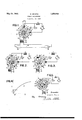
- Figure 1 is a diagrammatic view of the interrupter which is shown connected to a luminescent tube.
- Figure 2 is a diagrammatic view of the interrupter shown in Figure 1 in which the rotary element has been rotated through a small angle.
- FIG. 3 is a view of the interrupter in which the rotary element has been rotated through an -angle of 90 degrees from its position shown in Figure 2.
- Figure 4 is a graph of the current changes from the direct current supply with respect to time.
- Figure 5 shows a modification of the construction shown in Figures 1 to 3.
- the brushes 1 are in contact with a segmental ring or commutator 4'-5 which consists of four segments in the embodiment shown and the brushes are spaced one segmental distance apart, which in the four segment commutator separate the brushes by an angle of 90 degrees so that each brush rated from its adjacent segments by the in sulation 12 the circumferential dimension of which is less than the width of the brush in contact with the commutator.
- the brush is in contact with two of the segments and in this particular position the segment 5 makes a direct connection between the two brushes 1.
- Slip rings 7 and 9 are adapted to rotate with the segmental ring 45 and for that purpose may be mounted upon the same shaft although each slip ring must be electrically insulated from the other and also insulated from the commutator.
- a motor M having a drive connection of any suitable sort which is diagrammatically illustrated by the mem-- ber D, is used to rotate the segmental ring and the slip rings. This motor is very small and in fact a motor of 1/20 H. P is ample to drive the rings since it merely overcomes the friction of the brushes in contact with the rings and the friction ofthe bearings supporting the rings.
- segments of the segmental ring or commutator are connected to one of the slip rings and the other segments are connected to the other slip ring.
- A. brush 10 is in contact with. the slip ring F and a brush 11 is in contact with the slip ring 9, each brush being connected to an output terminal 17.
- a transformer having a primary coil 13 is connected the output terminals 17, while the secondary 14 of the transformer is connected to the electrodes 16 of'a luminescent tube 15. It is to be understood that although I have shown a transformer connected to the output terminals I 11 or terminals 17 may be utilized in any known manner.
- a switch preferably is provided in the direct current source connections as is usual in all electrical connections although not shown in the drawings.
- the commutator is rotated by the motor M through the driving connection D in the direction of the arrow. It was pointed out in detail above that the brushes 1 are wider than the insulation 12 separating the segments 1 and 5 so that the brush overlaps or is in contact with both segments when the brush asses from one segment to the next.
- the inductance 2 has been inserted in the connection tothe source of direct current in order to overcome the short circuit.
- An inductance has the characteristic of delayin or lagging the rate of increase in current ow such as results from a short circuit and it is this characteristic which is taken advantage of in my interrupter, by which the current is delayed or lagged long enough so that the brush passes completely from one segment to the next or through the period of the short circuit before a destructive current flows as a result of the short circuit. Without the inductance the current would increase enormously almost instantaneously and burn out some portion of the device or some connection.
- increasin current to time is graphically illustrated in igure 4 in which the abscissa of the graph denotes the time and the ordinate, the increase in current.
- the curve 18 is relatively flat which indicates that the current increases slowly during the time of the short circuit.
- the duration of the short circuit is a small fraction of a second and is in fact approximately equal to the time that it takes the commutator to rotate a distance equal to the width of the brush in contact with the commutator.
- the thickness of the insulation 2 reduces this time somewhat but it will not exceed the time referred to above which is represented by the angular distance dtas the maximum duration of the short circuit.
- This distance is also representative of the time duration of the short circuit and it has been shown in the graph as the distance dt along the abscissa.
- the increase in current at the end of the short circuit is therefore represented by I which shows a relatively small increase in current during this period.
- An in ductance of .1 henrys is suflicient to prevent a destructive current flow during the short circuit.
- the commutator continues its rotations to the position shown in Figure 3 and the flow of current when the ring is in this position is from the positive side of the source of supply through the-inductance 2, to the brush 1, to segment 4 and through the connection 6 to slip ring 7, to the brush 10 and then through the primary winding of the transformer 13 in the direction of the arrow to the brush 11 through the slip ring 9 and connection 8 to the segment 5 and brush 1 to the negative side of the supply S.
- the current through the primary 13 as illustrated by the arrow is in a direction opposite to that through the primary in the position of the commutator shown in Figure 2.
- the input brushes need not necessarily engage adjoining segments. ihe only requirement is that the input means or brushes, each engage a separate group of alternate segments and each brush be positioned in the same relative position with respect to the segments with which they are in contact so that as one brush leaves one segment during the rotation of the commutator the other brush is also leaving the segment with which'it is in contact.
- the input brushes 17 and 18 are then in con-.
- inductance 2 and condenser 3 are provided as shown in the other figures.
- An interrupter comprising a pair oi input means connected to a source of direct current, a condenser connected across the input means, means to short circuit the input means, an inductance in one of the input connections, a pair of output means connected to the input means, and means alternately rcversing the connections between the output means and the input means.
- An interupter comprising at pair of input means connected to a source 071 direct current, a condenser connected across the input means, means to short circuit the input means, an inductance in one of the input connections, a pair of output means, and means alternateiy reversing connections between the output and input means for changing the direction of current to the output means.
- A. rotary interrupter comprising a pair of input means connected to a source of direct current, a condenser connected across the input means, means to short circuit the input means, a pair of output means connected to the input means and a rotary means in contact with the input and output means for alternately reversing the connections between the output and input means for changing the direction of current to the output means.
- a rotary interrupter comprising a pair of input means connected to a source of direct current, a condenser connected across the input means, an inductance in one of the connections to the direct current source, a pair of output means connected to the input means, a rotary means in contact with the input and output means for alternately reversing the connections between the output and input means for changing the direction of current to the output means, and means to short circuit the input means between the reversals of current.
- rotary interrupter comprising a pair of input brushes connected to a source of di-a direct current source and spaced a segrect current, a condenser connected across the lnput brushes, an inductance 1n one of the connections to, the direct current source, a-
- a rotary interrupter comprising a pair I of input brushes connected to a source 0 direct current, a condenser connected across the input brushes, an inductance in one of the connections to the direct current source, a pair of output brushes, a rotary segmental ring having at least two segments insulated from each other and one of said airs of brushes in contact with the ring an so that the brushes of the pair are spaced from each other the distance of one segment, means connected to alternate se cuts of the segmental ring and engaged if; the other pair of brushes and means to short brushes.
- a rotary interrupter comprising a rotatable ring having at least two segments insulated from each other, a air of stationary input means in contact with the segmental ring connected to a direct current source and spaced apart a segmental length, means to rotate said ring, output terminals, means integral with the segmental ring connecting one group of alternate ring segments to one output terminal and the other segments to a second output terminal, and means to short circuit said input means.
- a rotary interrupter comprising a rotatable ring having at least two segments insulated from each other, a pair of stationary input means in contact with the segmental ring connected to a direct current source and spaced apart a segmental length, means to short circuit said input means, a condenser connected across said stationary means,
- a rotary interrupter comprising a rotary ring having two pairs of segments, a pair of means in contact with adjacent segments, and adapted to contact consecutively with each segment, a source of direct current connected to the pair of means, means to short circuit the said pair of means and a pair of output means one of which is connected to one alternate pair of segment of the rotary ring and the other of which is connected to the other pair of segments.
- a rotary interrupter comprising a rotatable ring having at least two segments insulated from each other, a pair of brushes in contact with the segmental ring connected to mental length apart, means to short circuit said brushes, a pair of slip rings directly rotatable with the segmental ring, connections joining alternate segments to one slip ring, connections joining the other segments to the secondslip ring, a slip ring brush in contact witheach slip ring for connection with the load, and driving means for-rotating the rlngs.
- a rotary interrupter comprising a rotatable ring having at least two segments, a pair of brushes in contact with the segmental ring connected to a direct current source and spaced 9. segmental length apart, insulating sections between the se ments having a length less than the len h o the brushes, a pair of slip rings rotata le with the segmental ring,
- connections joining alternate segments to one slip ring connections joining the other segments to the second slip ring, a slip ring brush in contact with each slip ring for connection with the load, and driving means for rotating the rings.
- a rotary interru ter comprising a rotatable ring having at east two segments, a pair of brushes in contact with the segmental ring connected to a direct current source and spaced a segmental length apart, insulating sections between the segments having a length less than the length of the brushes, a condenser connected across said brushes, a pair of slip rings rotatable with the segmental ring, connections joining alternate segments to one slip ring, connections joining the other segments to the second slip ring, a slip ring brush in contact with each slip ring for connection with the load, and driving means for rotating the rings.
- a rotary interrupter comprising a rotatable ring having at least two segments insulated from each other, a pair of brushes in contact with the segmental ring connected to a direct current source and spaced a segmental length apart, a condenser connected across said brushes, an inductance in the direct current source connection, means to short circuit said brushes, a pair of slip rings rotatable with the segmental ring, connections joining alternate segments to one slip ring, connections joining the other segments to the second slip ring, a slip ring brush in contact with each sli ring for connection with the load, and driving means for rotating the rings.
- a rotar interrupter comprising a rotatable ring aving at least two segments insulated from each other, a pair of brushes in contact with the segmental ring connected to a direct current source and spaced a segmental length apart, means to short circuit said brushes, a pair of slip rings directly rotatable with-the segmental ring, connections joining alternate segments to one slip ring, a slip ring brush in contact with each slipring, a transformer having its primary winding connected to the sli ring rushes' and its secondary to the load, and driving means for rotatingv the rings.
- a rotary interrupter comprising a air of input means connected to a source 0 direct current, a condenser connected across the input means, an inductance connected to one of said input means, a rotary ring having four segments, insulation between each segment being less in width than the width of the input means, a pair of slip rings each being connected to alternate segments of the rotary ring, and an output means contacting with each slip, ring.
- a rotary interrupter comprising a air of input means connected to a source 0' direct current, a condenser connected across the input means, an inductance connected to one of said input means, a rotary ring having four segments, insulation between each segment being less in widththan the width of the inputmeans, a pair of slip rings, each being connected to alternate segments of the rotary ring, an output means contacting with each slip ring, and a transformer having its primary winding connected to the output means.
- a rotary interrupter comprising a commutator having a plurality of segments, insulation electrically separating the segments, an output means connected to a group of alternate segments of the commutator, a second output means connected to the remaining segments of the commutator which form. a second group of alternate segments,
- said input means having a widthgreater than the insulation, and means to lag the current increase caused by the lnput means simultaneously engaging segments of the same group.
- a rotary interrupter comprising a commutator made up of a plurality'of segments, insulation electricallyseparating the segments, a pair of input means engaging the commutator a segmental distance apart and having a width greater than the insulation, and means to lag the current increase caused by the input means simultaneously engaging a single segment.
- a rotary interrupter comprising a commutator made up of a plurality of segments, insulation electrically separating the segments, a pair of input means engaging the commutator a segmental distance apart and having a widthgreaterthan the insulation, a pair of output means each of which is connected to alternate segments of the commutator and means to lag the current increase caused by the input means simultaneously engaging a single segment.
- a rotary interrupter comprising a segmental ring divided mto segments, contact means connecting adjacent se' ents with a direct current circuit inclu 'ng a source of direct current, means to short circuit said contact means, rings concentric with the segmental ring, electrical connection between alternate segments and the re spective said concentric rings, and other contact means connecting the said concentric rings with opposite terminals of a load,
- a rotary interrupter comprising a segmental ring divided into segments, contact means connecting adjacent segments with I a direct current circuit including a. source of direct current, means to short circuit said contact means, rings concentric with the segmental ring and rigidly joined thereto, electrical connection between alternate segments and the respective said concentric rings, and other contact means connecting the said concentric rings with opposite terminals of a load.
- a rotary interrupter comprising a segmental ring divided into four segments, contact means connecting adjacent segments with a direct current circuit including a source of direct current, means to short circuit said contact means, a condenser and an inductance, ringsconcentric with the seg- .mental ring, electrical connection between alternate segments and the respective said concentric rings, and other contact means connecting the said concentric rings with opposite terminals of a load.
Landscapes
- Engineering & Computer Science (AREA)
- Power Engineering (AREA)
- Motor Or Generator Current Collectors (AREA)
Description
Patented May 24, 1932 UNITEDQSTATES PATENT OFFICE CHARLES SPAETH, OF FLU SHING, YORK, ASSIGNOR '10 CLAUDE NEON LIGHTS,
' LNG, 0] NEW YORK, N. Y., A CORPORATION OF NEW YORK ROTARY INTERRUPTER Application filed October 20, 1928. Serial 1Y0. 813,?28.
This invention relates to a rotary interrupter which isadapted to convert direct current into alternating current, which may be used for lighting purposes such as luminous tubes used in advertising signs.
An object of the invention is to produce a rotary interrupter which has few parts and occupies a small amount of space.
Another object of the invention is to produce an interrupter having a minimum number of moving parts. 1
A further object of the invention is to produce a rotary interrupter having a low converting power loss.
Other objects, advantages and features of the construction willbe more clearly appar' ent from the detailed description below, taken in connection with the accompanying drawings in which Figure 1 is a diagrammatic view of the interrupter which is shown connected to a luminescent tube.
Figure 2 is a diagrammatic view of the interrupter shown in Figure 1 in which the rotary element has been rotated through a small angle.
'Figure 3 is a view of the interrupter in which the rotary element has been rotated through an -angle of 90 degrees from its position shown in Figure 2. V
Figure 4 is a graph of the current changes from the direct current supply with respect to time.
Figure 5 shows a modification of the construction shown in Figures 1 to 3.
My invention, as shown in Figure 1, con sists of the brushes 1 connected to a source of direct current which is diagrammatically illustrated by the generator S. An inductance 2 is inserted in one of the brush connections, preferably the positive connection from the generator, and a condenser 3 is connected across the brushes 1. The purposes of the inductance and the condenser will he explained in detail later. I
The brushes 1 are in contact with a segmental ring or commutator 4'-5 which consists of four segments in the embodiment shown and the brushes are spaced one segmental distance apart, which in the four segment commutator separate the brushes by an angle of 90 degrees so that each brush rated from its adjacent segments by the in sulation 12 the circumferential dimension of which is less than the width of the brush in contact with the commutator. As shown in Figure l, the brush is in contact with two of the segments and in this particular position the segment 5 makes a direct connection between the two brushes 1.
Slip rings 7 and 9 are adapted to rotate with the segmental ring 45 and for that purpose may be mounted upon the same shaft although each slip ring must be electrically insulated from the other and also insulated from the commutator. A motor M having a drive connection of any suitable sort which is diagrammatically illustrated by the mem-- ber D, is used to rotate the segmental ring and the slip rings. This motor is very small and in fact a motor of 1/20 H. P is ample to drive the rings since it merely overcomes the friction of the brushes in contact with the rings and the friction ofthe bearings supporting the rings.
Alternate segments of the segmental ring or commutator are connected to one of the slip rings and the other segments are connected to the other slip ring. This is shown in Figure 1, where segments are connected by means of wires or connections 6 to the slip ring 7 and the segmentsh are connected through members 8 to the slip ring 9. A. brush 10 is in contact with. the slip ring F and a brush 11 is in contact with the slip ring 9, each brush being connected to an output terminal 17. A transformer having a primary coil 13 is connected the output terminals 17, while the secondary 14 of the transformer is connected to the electrodes 16 of'a luminescent tube 15. It is to be understood that although I have shown a transformer connected to the output terminals I 11 or terminals 17 may be utilized in any known manner.
Proceeding now to the operation of the interrupter, and the manner in which I convert direct current into alternating current, it will be noted that a switch preferably is provided in the direct current source connections as is usual in all electrical connections although not shown in the drawings. The commutator is rotated by the motor M through the driving connection D in the direction of the arrow. It was pointed out in detail above that the brushes 1 are wider than the insulation 12 separating the segments 1 and 5 so that the brush overlaps or is in contact with both segments when the brush asses from one segment to the next. Tracing the flow of current when the commutator is in this position, it will'-'=be seen that the current from the positive side of the direct current source S passes through the inductance 2, and brush 1 to the segments 4 and 5 of the commutator. The current then takes a path through segment 5 to the brush 1 on the negative side of the source, this path having less resistance, and in fact segment 5 forms a direct short circuit between the brushes. It is apparent then that a short circuit occurs through each segment as the brushes 1 pass from one segment to the other as the segmental ring or commutator is rotated and exists only so long during the rotation of the commutator as the two brushes are in contact with the same segment. The period of the short circuit is represented by the angular distance dt and the actual time of the short circuit is the time it takes the commutator to rotate this distance.
The inductance 2 has been inserted in the connection tothe source of direct current in order to overcome the short circuit.
An inductance has the characteristic of delayin or lagging the rate of increase in current ow such as results from a short circuit and it is this characteristic which is taken advantage of in my interrupter, by which the current is delayed or lagged long enough so that the brush passes completely from one segment to the next or through the period of the short circuit before a destructive current flows as a result of the short circuit. Without the inductance the current would increase enormously almost instantaneously and burn out some portion of the device or some connection.
The relation of increasin current to time is graphically illustrated in igure 4 in which the abscissa of the graph denotes the time and the ordinate, the increase in current. As will be noted the curve 18 is relatively flat which indicates that the current increases slowly during the time of the short circuit. The duration of the short circuit is a small fraction of a second and is in fact approximately equal to the time that it takes the commutator to rotate a distance equal to the width of the brush in contact with the commutator. The thickness of the insulation 2 reduces this time somewhat but it will not exceed the time referred to above which is represented by the angular distance dtas the maximum duration of the short circuit. This distance is also representative of the time duration of the short circuit and it has been shown in the graph as the distance dt along the abscissa. The increase in current at the end of the short circuit is therefore represented by I which shows a relatively small increase in current during this period. An in ductance of .1 henrys is suflicient to prevent a destructive current flow during the short circuit.
The manner in which the conversion of the direct current to alternating current takes place will be best understood by tracing the current flow as the commutator and slip rings rotate.
In Figure 2 the current flows from the positive side of the source S and passes through the inductance 2 to the brush 1, through the segment 5 and the connection 8 to the slip ring 9 where it is picked up by the brush 11. The current then passes through the primary winding of the transformer 13 in the direcs tion shown by the arrow to the brush 10 which is in contact with the slip ring 7, and through the slip ring 7 to the connection 6 to segment 4 to the brush 1 and then to the negative side of the source of supply.
The commutator continues its rotations to the position shown in Figure 3 and the flow of current when the ring is in this position is from the positive side of the source of supply through the-inductance 2, to the brush 1, to segment 4 and through the connection 6 to slip ring 7, to the brush 10 and then through the primary winding of the transformer 13 in the direction of the arrow to the brush 11 through the slip ring 9 and connection 8 to the segment 5 and brush 1 to the negative side of the supply S. It will be seen therefore that the current through the primary 13 as illustrated by the arrow is in a direction opposite to that through the primary in the position of the commutator shown in Figure 2. These alternations of current through the primary winding 13 and the transformer set up corresponding altternations in the secondary 14 which furnishes an alternating current to the terminals 16 of the.
not overlap the insulation and engage two segments when passing from one segment to the next, the short circuiting through the seglo nients can be avoided and the inductance with. However a condenser 3 of very large capacity must then be connected across the brushes in order to prevent sparking. In my interrupter I can successfully prevent sparking with a condenser. of relatively small capacity which is in the neighborhood of 4 microfarads and I attribute this result to my construction.
Various modifications and changes will be 8 apparent to those skilled in the art in practicing the invention described. These'modifications may take the form of increasing or decreasing the number of segments in the commutator thereby increasing or decreasing .the number of alternations in one revolution. The number of revolutions per minute of the ordinary electric motor is 1800 and with the four segments in the commutator 3600 alternations will be produced per minute which is at the rate of 60 per second or at the frequency of the usual lighting circuits. It is apparent then that by increasing the number of segments any frequency may be selected or the same result may be secured by increasing the number of'revolutions per minute of the commutator.
It is clear that when a large number of segments are used in the commutator in order to secure a great number of alternations per in unit of time or when a slow speed motor is used and the usual lighting frequency of 60 cycles per second is desired, the input brushes need not necessarily engage adjoining segments. ihe only requirement is that the input means or brushes, each engage a separate group of alternate segments and each brush be positioned in the same relative position with respect to the segments with which they are in contact so that as one brush leaves one segment during the rotation of the commutator the other brush is also leaving the segment with which'it is in contact. I
Another modification is shown in Figure in which the output brushes and 26, which are connected to the primary winding 13 of the output transformer, are in contact with the commutator made up of segments 21 insulated from each other by members 22. Alternate segments of the commutator are connected through wires 24 to the slip ring 19 and the other segments are connected through a connection 23 to the slip ring 20.
The input brushes 17 and 18 are then in con-.
tact with the slip rings 19 and 20. In other.
words the input brushes are now engaging the .which creates a current lag can be dispensed.
slip rings and the output brushes are engaging the commutator. The output brushes 25 and 26 must therefore .be separated by a segmental distance which in the four-segment commutator will be 90 degrees apart as in theembodiment shown in Figures 1-3. The
In the practice of my invention it is furthermore immaterial to the successful results secured therefrom whether the brushes rotate with respect to the commutator or whether the commutator rotates with respect to the brushes and either form of construction is contemplated herein.
I have illustrated and described herewith what I regard as the preferred embodiment of my invention but it is to be expressly understood that I do not limit myself thereto as many changes and modifications may be made in points of detail without deviating from the spirit and scope of my invention.
What I claim is:
1. An interrupter comprising a pair oi input means connected to a source of direct current, a condenser connected across the input means, means to short circuit the input means, an inductance in one of the input connections, a pair of output means connected to the input means, and means alternately rcversing the connections between the output means and the input means.
2. An interupter comprising at pair of input means connected to a source 071 direct current, a condenser connected across the input means, means to short circuit the input means, an inductance in one of the input connections, a pair of output means, and means alternateiy reversing connections between the output and input means for changing the direction of current to the output means.
3. A. rotary interrupter comprising a pair of input means connected to a source of direct current, a condenser connected across the input means, means to short circuit the input means, a pair of output means connected to the input means and a rotary means in contact with the input and output means for alternately reversing the connections between the output and input means for changing the direction of current to the output means.
4:. A rotary interrupter comprising a pair of input means connected to a source of direct current, a condenser connected across the input means, an inductance in one of the connections to the direct current source, a pair of output means connected to the input means, a rotary means in contact with the input and output means for alternately reversing the connections between the output and input means for changing the direction of current to the output means, and means to short circuit the input means between the reversals of current. I
5. rotary interrupter comprising a pair of input brushes connected to a source of di-a direct current source and spaced a segrect current, a condenser connected across the lnput brushes, an inductance 1n one of the connections to, the direct current source, a-
pair of output brushes, a rotary means in contact with the output and input brushes for alternately reversing the connections between the output and input means for changing the direction of current to the output means and means to short circuit the input current at each reversal.
6. A rotary interrupter comprising a pair I of input brushes connected to a source 0 direct current, a condenser connected across the input brushes, an inductance in one of the connections to the direct current source, a pair of output brushes, a rotary segmental ring having at least two segments insulated from each other and one of said airs of brushes in contact with the ring an so that the brushes of the pair are spaced from each other the distance of one segment, means connected to alternate se cuts of the segmental ring and engaged if; the other pair of brushes and means to short brushes.
7. A rotary interrupter comprising a rotatable ring having at least two segments insulated from each other, a air of stationary input means in contact with the segmental ring connected to a direct current source and spaced apart a segmental length, means to rotate said ring, output terminals, means integral with the segmental ring connecting one group of alternate ring segments to one output terminal and the other segments to a second output terminal, and means to short circuit said input means.
8. A rotary interrupter comprising a rotatable ring having at least two segments insulated from each other, a pair of stationary input means in contact with the segmental ring connected to a direct current source and spaced apart a segmental length, means to short circuit said input means, a condenser connected across said stationary means,
circuit said input means to rotate said ring, output terminals,
and means connecting one group of alternate ring segments to one output terminal and the other segments to a second output terminal.
9. A rotary interrupter comprising a rotary ring having two pairs of segments, a pair of means in contact with adjacent segments, and adapted to contact consecutively with each segment, a source of direct current connected to the pair of means, means to short circuit the said pair of means and a pair of output means one of which is connected to one alternate pair of segment of the rotary ring and the other of which is connected to the other pair of segments.
10. A rotary interrupter comprising a rotatable ring having at least two segments insulated from each other, a pair of brushes in contact with the segmental ring connected to mental length apart, means to short circuit said brushes, a pair of slip rings directly rotatable with the segmental ring, connections joining alternate segments to one slip ring, connections joining the other segments to the secondslip ring, a slip ring brush in contact witheach slip ring for connection with the load, and driving means for-rotating the rlngs.
11. A rotary interrupter comprising a rotatable ring having at least two segments, a pair of brushes in contact with the segmental ring connected to a direct current source and spaced 9. segmental length apart, insulating sections between the se ments having a length less than the len h o the brushes, a pair of slip rings rotata le with the segmental ring,
connections joining alternate segments to one slip ring, connections joining the other segments to the second slip ring, a slip ring brush in contact with each slip ring for connection with the load, and driving means for rotating the rings.
12. A rotary interru ter comprising a rotatable ring having at east two segments, a pair of brushes in contact with the segmental ring connected to a direct current source and spaced a segmental length apart, insulating sections between the segments having a length less than the length of the brushes, a condenser connected across said brushes, a pair of slip rings rotatable with the segmental ring, connections joining alternate segments to one slip ring, connections joining the other segments to the second slip ring, a slip ring brush in contact with each slip ring for connection with the load, and driving means for rotating the rings.
13. A rotary interrupter comprising a rotatable ring having at least two segments insulated from each other, a pair of brushes in contact with the segmental ring connected to a direct current source and spaced a segmental length apart, a condenser connected across said brushes, an inductance in the direct current source connection, means to short circuit said brushes, a pair of slip rings rotatable with the segmental ring, connections joining alternate segments to one slip ring, connections joining the other segments to the second slip ring, a slip ring brush in contact with each sli ring for connection with the load, and driving means for rotating the rings.
14. A rotar interrupter comprising a rotatable ring aving at least two segments insulated from each other, a pair of brushes in contact with the segmental ring connected to a direct current source and spaced a segmental length apart, means to short circuit said brushes, a pair of slip rings directly rotatable with-the segmental ring, connections joining alternate segments to one slip ring, a slip ring brush in contact with each slipring, a transformer having its primary winding connected to the sli ring rushes' and its secondary to the load, and driving means for rotatingv the rings.
15. A rotary interrupter comprising a air of input means connected to a source 0 direct current, a condenser connected across the input means, an inductance connected to one of said input means, a rotary ring having four segments, insulation between each segment being less in width than the width of the input means, a pair of slip rings each being connected to alternate segments of the rotary ring, and an output means contacting with each slip, ring.
16. A rotary interrupter comprising a air of input means connected to a source 0' direct current, a condenser connected across the input means, an inductance connected to one of said input means, a rotary ring having four segments, insulation between each segment being less in widththan the width of the inputmeans, a pair of slip rings, each being connected to alternate segments of the rotary ring, an output means contacting with each slip ring, and a transformer having its primary winding connected to the output means.
17. A rotary interrupter comprising a commutator having a plurality of segments, insulation electrically separating the segments, an output means connected to a group of alternate segments of the commutator, a second output means connected to the remaining segments of the commutator which form. a second group of alternate segments,
a segment of the second group, said input means having a widthgreater than the insulation, and means to lag the current increase caused by the lnput means simultaneously engaging segments of the same group.
18. A rotary interrupter comprising a commutator made up of a plurality'of segments, insulation electricallyseparating the segments, a pair of input means engaging the commutator a segmental distance apart and having a width greater than the insulation, and means to lag the current increase caused by the input means simultaneously engaging a single segment.
19. A rotary interrupter comprising a commutator made up of a plurality of segments, insulation electrically separating the segments, a pair of input means engaging the commutator a segmental distance apart and having a widthgreaterthan the insulation, a pair of output means each of which is connected to alternate segments of the commutator and means to lag the current increase caused by the input means simultaneously engaging a single segment.
20. A rotary interrupter comprising a segmental ring divided mto segments, contact means connecting adjacent se' ents with a direct current circuit inclu 'ng a source of direct current, means to short circuit said contact means, rings concentric with the segmental ring, electrical connection between alternate segments and the re spective said concentric rings, and other contact means connecting the said concentric rings with opposite terminals of a load,
21. A rotary interrupter comprising a segmental ring divided into segments, contact means connecting adjacent segments with I a direct current circuit including a. source of direct current, means to short circuit said contact means, rings concentric with the segmental ring and rigidly joined thereto, electrical connection between alternate segments and the respective said concentric rings, and other contact means connecting the said concentric rings with opposite terminals of a load.
22. A rotary interrupter comprising a segmental ring divided into four segments, contact means connecting adjacent segments with a direct current circuit including a source of direct current, means to short circuit said contact means, a condenser and an inductance, ringsconcentric with the seg- .mental ring, electrical connection between alternate segments and the respective said concentric rings, and other contact means connecting the said concentric rings with opposite terminals of a load.
In testimony whereof I aflix m signature.
CHARLES S AETH.
an input means engaging a segment of the first group, a second input means engaging
Priority Applications (1)
| Application Number | Priority Date | Filing Date | Title |
|---|---|---|---|
| US31372328 US1859940A (en) | 1928-10-20 | 1928-10-20 | Rotary interrupter |
Applications Claiming Priority (1)
| Application Number | Priority Date | Filing Date | Title |
|---|---|---|---|
| US31372328 US1859940A (en) | 1928-10-20 | 1928-10-20 | Rotary interrupter |
Publications (1)
| Publication Number | Publication Date |
|---|---|
| US1859940A true US1859940A (en) | 1932-05-24 |
Family
ID=23216864
Family Applications (1)
| Application Number | Title | Priority Date | Filing Date |
|---|---|---|---|
| US31372328 Expired - Lifetime US1859940A (en) | 1928-10-20 | 1928-10-20 | Rotary interrupter |
Country Status (1)
| Country | Link |
|---|---|
| US (1) | US1859940A (en) |
Cited By (3)
| Publication number | Priority date | Publication date | Assignee | Title |
|---|---|---|---|---|
| US2449077A (en) * | 1943-01-27 | 1948-09-14 | Rca Corp | Power converter |
| FR2589647A1 (en) * | 1985-11-04 | 1987-05-07 | Electricite De France | Variable-frequency supply device with electromechanical collector |
| US4717995A (en) * | 1986-05-17 | 1988-01-05 | Garcia Juan O | Procedure for converting direct electrical energy into alternating electrical energy |
-
1928
- 1928-10-20 US US31372328 patent/US1859940A/en not_active Expired - Lifetime
Cited By (3)
| Publication number | Priority date | Publication date | Assignee | Title |
|---|---|---|---|---|
| US2449077A (en) * | 1943-01-27 | 1948-09-14 | Rca Corp | Power converter |
| FR2589647A1 (en) * | 1985-11-04 | 1987-05-07 | Electricite De France | Variable-frequency supply device with electromechanical collector |
| US4717995A (en) * | 1986-05-17 | 1988-01-05 | Garcia Juan O | Procedure for converting direct electrical energy into alternating electrical energy |
Similar Documents
| Publication | Publication Date | Title |
|---|---|---|
| US1859940A (en) | Rotary interrupter | |
| US2553298A (en) | Magneto generator | |
| US2164964A (en) | Direct current transformer | |
| US2042334A (en) | Low voltage generator | |
| US3205427A (en) | Phase-cycle transmutor | |
| US2242343A (en) | Reversible capacttor motor | |
| US2182628A (en) | Conversion system | |
| US1199469A (en) | Mechanical rectifier. | |
| US2565005A (en) | Device for rectifying alternating current | |
| US727662A (en) | Induction-motor for variable speeds. | |
| US3333177A (en) | Selective control of frequency and voltage in alternating current power systems | |
| CN1206796C (en) | Mechanical inverter of alternating current permanent magnet motor | |
| US2090010A (en) | Rotary inverter and rectifier | |
| US2358926A (en) | Commutation means and a method of commutation | |
| US1119397A (en) | Current-transforming device. | |
| US2389507A (en) | Commutation means for rotary rectifiers | |
| US1201687A (en) | Current-transforming device. | |
| US1267969A (en) | Current-converting machine. | |
| US1199468A (en) | Mechanical rectifier. | |
| US2339794A (en) | Apparatus for rectifying electric current | |
| US1203266A (en) | Alternating-electric-current rectifier. | |
| US1259160A (en) | Apparatus for rectifying high-potential alternating and oscillating currents and electromotive forces. | |
| US2255795A (en) | Device for converting multiphase alternating current into direct current | |
| US1212874A (en) | Mechanical rectifier. | |
| SU20223A1 (en) | Mechanical ac rectifier |