US1859939A - Electric fluid heater - Google Patents
Electric fluid heater Download PDFInfo
- Publication number
- US1859939A US1859939A US323271A US32327128A US1859939A US 1859939 A US1859939 A US 1859939A US 323271 A US323271 A US 323271A US 32327128 A US32327128 A US 32327128A US 1859939 A US1859939 A US 1859939A
- Authority
- US
- United States
- Prior art keywords
- housing
- core
- heater
- base
- fluid
- Prior art date
- Legal status (The legal status is an assumption and is not a legal conclusion. Google has not performed a legal analysis and makes no representation as to the accuracy of the status listed.)
- Expired - Lifetime
Links
- 239000012530 fluid Substances 0.000 title description 43
- XLYOFNOQVPJJNP-UHFFFAOYSA-N water Substances O XLYOFNOQVPJJNP-UHFFFAOYSA-N 0.000 description 29
- 238000010438 heat treatment Methods 0.000 description 21
- 239000011810 insulating material Substances 0.000 description 12
- 238000003860 storage Methods 0.000 description 8
- 238000005485 electric heating Methods 0.000 description 6
- 239000000463 material Substances 0.000 description 6
- 239000004020 conductor Substances 0.000 description 5
- 239000013049 sediment Substances 0.000 description 5
- 238000009434 installation Methods 0.000 description 4
- 239000007788 liquid Substances 0.000 description 4
- 229910052751 metal Inorganic materials 0.000 description 4
- 239000002184 metal Substances 0.000 description 4
- 238000000034 method Methods 0.000 description 4
- 229910052573 porcelain Inorganic materials 0.000 description 4
- 230000000284 resting effect Effects 0.000 description 4
- 239000007787 solid Substances 0.000 description 4
- 229910052782 aluminium Inorganic materials 0.000 description 3
- XAGFODPZIPBFFR-UHFFFAOYSA-N aluminium Chemical compound [Al] XAGFODPZIPBFFR-UHFFFAOYSA-N 0.000 description 3
- 230000001174 ascending effect Effects 0.000 description 3
- 210000003141 lower extremity Anatomy 0.000 description 3
- 239000004568 cement Substances 0.000 description 2
- 230000003247 decreasing effect Effects 0.000 description 2
- 125000006850 spacer group Chemical group 0.000 description 2
- 238000005299 abrasion Methods 0.000 description 1
- 238000004140 cleaning Methods 0.000 description 1
- 229940000425 combination drug Drugs 0.000 description 1
- 238000010276 construction Methods 0.000 description 1
- 230000007547 defect Effects 0.000 description 1
- 238000004512 die casting Methods 0.000 description 1
- 238000010292 electrical insulation Methods 0.000 description 1
- 239000008236 heating water Substances 0.000 description 1
- 238000007373 indentation Methods 0.000 description 1
- 238000003825 pressing Methods 0.000 description 1
- 238000007665 sagging Methods 0.000 description 1
- 238000007789 sealing Methods 0.000 description 1
Images
Classifications
-
- F—MECHANICAL ENGINEERING; LIGHTING; HEATING; WEAPONS; BLASTING
- F24—HEATING; RANGES; VENTILATING
- F24H—FLUID HEATERS, e.g. WATER OR AIR HEATERS, HAVING HEAT-GENERATING MEANS, e.g. HEAT PUMPS, IN GENERAL
- F24H1/00—Water heaters, e.g. boilers, continuous-flow heaters or water-storage heaters
- F24H1/18—Water-storage heaters
- F24H1/20—Water-storage heaters with immersed heating elements, e.g. electric elements or furnace tubes
-
- F—MECHANICAL ENGINEERING; LIGHTING; HEATING; WEAPONS; BLASTING
- F24—HEATING; RANGES; VENTILATING
- F24H—FLUID HEATERS, e.g. WATER OR AIR HEATERS, HAVING HEAT-GENERATING MEANS, e.g. HEAT PUMPS, IN GENERAL
- F24H9/00—Details
- F24H9/18—Arrangement or mounting of grates or heating means
- F24H9/1809—Arrangement or mounting of grates or heating means for water heaters
- F24H9/1818—Arrangement or mounting of electric heating means
Definitions
- My invention relates to improvements in electric fluid heaters of the outside circulation type wherein the heat from the electrical element is imparted directly to the fluid; and to the method of installing and operating the samewith particular refere ce to the use of the invention for heating water.
- Electric water heaters of various kinds have been devised in repeated attempts to i@ profit by the faster and more eflicient operation resulting from the heating of water by direct Contact with the electrical element, but heretofore these attempts have met with meager success in practice because of various is inherent electrical and hydraulic defects which are eliminated in my invention, as herein afterl explained.
- the chief object of my invention is to provide a simple, compact reliable device of the 2o kind described that is cheap to manufactrre, easy to install and economical to operate.
- .finother object is to provide a water heater that may be used readily in combination with a storage tank, faucet or the like to provide a good supply of hot water quickly after current thereto is turned on.
- a further object is to provide a iiuid heater adapted be supported by the connecting piping, wherein the heating clement of the e i same may be easily removed for cleaning or renewal without disturbing said piping.
- a still further and important object is to provide means in such heaters whereby the flow of liquid through the same, together with the method of installation and operation are effective in preventing the deposit of sediment which may render the heater inoperative. and to provide means for completely enclosing and insulating the terminal posts near the bottom of the housing to safeguard them against being shortcircuited by deposits of sediment.
- An additional object is to provide substantial and adequate electrical insulation for the terminals of the heater; with particular reference to the means of insulating said termin als against the short circuiting tendency of sedimentary deposits.
- a final object is to provide means for re- J ducing the electrolytic action in a heater of the kind described, by employing an insulating lining for the heater housing and by constructing the housing of a material that electrolyt-ically is relatively inactive.
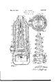
- Figure 1 is a vertical mid-section of a water heater embodying the invention.
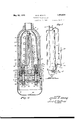
- Fig. 2 is a sectional view of the same taken at A-A of Fig. l.
- Fig. 3 is an elevation cf the removable heating element and certain insulating parts used to mount and support the same.
- Fig. 4 is a view in vertical mid-section, taken through the vertical axes of the terminals.
- Fig. 5 is an elevation of a typical installation showing the preferred method of installing the heater in combination with a hot water storage tank.
- a tubular housing member 6 preferably made of commercially pure die cast aluminum, is closed at one end with a spherically shaped head 7 in which a threaded opening 8 is provided for the reception of the threaded end of discharge pipe 9, which also serves as one of the supports for the heater.
- a boss 10 extending radially from the housing adjacent the lower end thereof has a threaded opening 11 for the reception of threaded inlet piping 12 which also serves as a support for the heater.
- housing 6 may be provided with a true surface 13 and interior threads 1.4 which are adapted to receive a threaded base member l5, also preferably a commercially pure aluminum die casting.
- the base has a shoulder 16 with a true surface 17 so that a water tight joint may be made by using two ordinary wrenches, not shown, one of which would engage the flats of the raised twelve sided portion 6 of housing 6, and the other would be used on the flat parallel side 18 at the lower extremity of the base, the two wrenches being so operated as corresponding openings 23. in a base liner 2st,
- terminal block 25 both preferably of porcelain.
- gasket Washers 26 are so shaped; and sized as tofextend bcyond the edges of'spacerfblocks29, thus proe viding a cushion seat that' compensates for the*V ,small irregularities of' the ⁇ porcelain "i members thus separated', and also assist in formingl a water tight joint at' these points when nutsr are tightened;
- the heating element 34 consists of a coiled resistancer wire of suitablev material which 1s wrapped spirally about core 32 as illustrated clearly inA Fig. 3, of: the drawings.
- the lower end of the spiral' is both mechanically secured and electrically' connected to one of the terminals 215 by'means of washer 35 ⁇ and nut, while the upper end of the coil is coning 38 to facilitate the assembling operation.
- the additional wire from the joint to the terminal post 21 constitutes means for increasing the conductivity of the conductor section within the core so that if water circulation through this portion of the core is stopped this section of the Wire will not be burned. out.
- An insulating lining/10 preferably of porcelain,A is positioned Within housing 6' by means of a rubber band' 40', with openings in the side at 4l and in the top at 42 for the entrance and egress respectively of the water.
- The-band 40 alsoserves as a seal to prevent water circulation between the exterior of liner Gand the housing.
- Housing liner 40 in combination with base liner 24 serve t0 electrically insulate the heating element from the metal housing and base, and also serve to conserve the heat generated within the heater by virtue of the low heat conductivit of the insulatingl material.
- Luge 61 near the top of the housing furtherassist in holding the lining 40straight and a slot 62 in the bottom of the lining which fits over a key lug 63 in the housing compels the correct positioning of the lining rotatively.
- heating element 34 and housing 6 or base 15v Any tendency for electrolytic action between heating element 34 and housing 6 or base 15v is practically eliminated by using alternating current derived preferably from the secondary coil of a transformer, not shown, the mid point ofl said coil being grounded on the piping supplying water to the heater; and by making the housing and base of commercially pure aluminum.
- a threaded opening 43 provided in the skirt of base member 15 is adapted to receive the threaded end of a conduit 44 through which the electricalv conductors are drawn. After said conductors are connected to terminal'screws 21 by means of cupped Washers and nuts 46, the installation is completed by pressing into place a thin metal terminal space cover 47 which fits snugly over base member 15. A hole 48 is provided in the bottom of cover 47 for drainage purposes and to facilitate its removal from base 15.
- Discharge piping 9 is pref# eraoly of larger diameter than inlet piping 12 to allow for the expansion of the water as its temperature is raised in passing through the heater.
- An electric fluid heater embodying a housing having a water inlet and a water outlet, aV tapered core disposed axially within said housing, a heating element carried by said core in direct contact with the Water to be heated, a lining of solid insulating material within the housing surrounding said element, and a plate of insulating material within the bottom of said housing, said insulating lining and plate serving to reduce electrolytic action in the heater.
- An electric fluid heater embodying a housing having bottom water inlet and top outlet openings, an electric heating element disposed vertically Within said housing, and a lining ofy solid insulating material surrounding the heating element for reducing electrolytic action in said heater, said lining being larger at the lower end and converging toward the upper end to gradually increase the velocity of flow as the water expands and ascends past the heating element.
- An electric fluid heater embodying an upright cylindrical housing, having a water outletat its top end and water inlet near its bottom end. a core converging from the bottom upward disposed axially within said housing, an electric heating coil wound spirallyV on said core in direct contact withthe water to be heated. and a lining of solid insul'ating material disposed within the housing and surrounding said core for reducing electrolytic action in said heater, said lining converging from the bottom upwardly to afford a passageway of decreasing area around said core from the bottom to the top of the same. 5.
- An electric fluid heater embodying an upright cylindrical housing of electrolytically inactive material having a water.
- a core disposed axially within said housing, an electric heating coil wound spi'- rallv on said core, a plate of insulating material in the bottom of the housing below said core, and a lining of insulating material disposed witliin the housing with its bottom end in close relation to said insulating plate and surrounding the core, the diameter of the bottom end of said lining being substantiall ly equal to the inside diameter of the housing and the interior walls of said lining converging from the bottom upwardly and'said lining havingr a centrally arranged opening formed at the top end thereof.
- An electric fluid heater embodying an uprightv cylindrical. housing, .having a. water outlet4 atv itsv top Y end and a water inletl near its'bottom end, a coreidisposed axially withinsaid housing,.an electric lieatingxcoil wound spirally'on said'core,.and a' conical lining'ofV insulating material disposedwithin said housing and surrounding said core, the bottom of saidlining substantially filling said housing.
- said'lining converging toward its upper end forming a sediment: spacev between'I the walls ofthe housing and the lining and forming a fluid passageway of decreasing area from bottom to top around said core, said lining terminating at itsupper end in a spherical section-having a-centrally arranged' opening.
- An electric fluid heater embodying an upright housing, having fluid inletr and outlet means, a tubular core of'insulating material mounted axially Within said housing, two terminal postsat the base of said core, andr an electric heating coil wound spirally on said'core, the lower end of said coil being.
- An electric fluid heater embodying a housing having fluid inlet and fluid outlet means, a core ofiinsulating'material mountedr vertically within said housing and having a longitudinal passageway provided therein, an electric heating coil carried on .the exterior of said core, two terminal posts at the bottom of said core, the lower en'd of said coil being a passageway of restricted areaaround thel core whereby the fluid is brought into direct contact with. the heating element and said heating element tends to impart a spirali" movement to the Water.
- An electric fluid heater embodying a cylindrical housing, a core of insulating inaterial mounted axially within said housing.
- said core havingV an oval base, spacer means positioned near the ends of said oval base and supporting the core in spaced relation above the bottom of the housing, fluid outlet means at the top of said housing and means for directing fluid into the side of said housing between said spacer means and between said oval base and the bottom ot said housing.
- An electric fluid heater embodying a housing, an insulating lining within said housing, a plate of insulating material within the bottom of said housing, a fluid inlet pipe connected with the side of said housing i'or delivering liquid therein just above said insulating plate, a core of insulating material disposed axially within said housing and surrounded by said lining, means supporting said core in spaced relation above said insulating plate and leaving an unobstructed fluid passageway under the central portion of the core, a heating coil carried by said core and fluid outlet means connected with the top of said housing.
- An electric fluid heater embodying a cylindrical housing having a bottom, a fluid inlet pipe connected with the side of said housing substantially tangent to the plane of said bottom, a core of insulating material disposed axially within said housing having a longitudinal passageway provided therein, an oval shaped base formed on said core, means interposed between the ends of said base and the bottom of said housing for sup- 4 porting said base in spaced relation above said housing bottom and leaving an unobstructed passageway underneath the central portion of said base, the major axis of said base being arranged at right angles to the axis of the inlet pipe, said oval shaped base leaving crescent shaped fluid passageways on opposite sides between the edges of the base and the sides of the housing, a heating coil on said core, and fluid outlet means at the top of said housin 14.
- n electric fluid heater embodying a cylindrical housing having a spherical upper end provided with a fluid outlet, a removable base arranged to be screwed into the bottom of said housing, spaced apart terminal posts extending upwardly through said base, an insulating plate resting on the top ot said base, nuts on the bottom ends of said terminal posts, insulating blocks resting on said insulating plate, an upright hollow core having a base supported on said blocks, whereby an open space is left under said coil base between said blocks, said terminal posts extending up through said core base, all parts of said terminals between the bottom of said housing and the top of said core base being completely enclosed and insulated, nuts on the top ends of said posts, a horizontal fluid inlet pipe connected with the side of said housing in alignment with said open space, a heating coil wound spirally on said core, the lower end of said coil being connected with one of said terminal posts, conductor means extending lengthwise within said core and connecting the upper end of said coil with the other terminal post and a lining disposed within said housing and surrounding
- An electric fluid heater embodying a cylindrical housing having a spherical upper end provided with a liuid outlet, a removable base arranged to be screwed into the bottom of said housing, spaced apart terminal posts extending up wai-diy through said base, sij on said posts insulating the same from said base, a plate of insulating material beneath said base, another plate of insulating material on the upper side of' said base, gaskets between said insulating plates ancL said base, means sealing the ends of said tubes within said insulating plates,nuts on the bottom ends of said terminal posts, insulating blocks resting on said upper insulating plate, an upright hollow core having a base resting on said blocks, whereby an open space is lett under said core base between said blocks, said terminal posts, extending upwardly through said base, a horizontal fluid inletl pipe connected with the side of said housing in alignment with said space, a heating coil wound spirally on said core, the lower end of said coil being connected with one ot
- An electric fluid heaterembody comprisingatubular housing open at the bottom end, a removable base for closing said open bottom end, a fluid outlet conduit at the top of said housing, fluid inlet means entering the side of said housing near the bottom end, an electric heating element extending axially within said housing, a lining arranged to lit within said housing and surround said heating element' and having an opening on one side near its bottom end arranged to register with said fluid inlet conduit and means for compelling the correct positioning of said lining rotatirely within said housing.
- a direct current electric fluid heater an upright housing provided with fluid circulation means, a heating element within said housing and disposed directly within the fluid which circulates in said housing, terminal screws extending upwardly through the bot-tom ot said housing and connected 7ith the heating element electrically and supporting said heating element in spaced relation above the bottom of said housing, and insulating means completely enclosing said terminal screws between the bottom of the housing and the base of the electric heater For preventing the grounding and short llU circuiti'ng -of said terminal lscrews :by ⁇ vsedimentary deposits.
Landscapes
- Engineering & Computer Science (AREA)
- Physics & Mathematics (AREA)
- Thermal Sciences (AREA)
- Chemical & Material Sciences (AREA)
- Combustion & Propulsion (AREA)
- Mechanical Engineering (AREA)
- General Engineering & Computer Science (AREA)
- Instantaneous Water Boilers, Portable Hot-Water Supply Apparatuses, And Control Of Portable Hot-Water Supply Apparatuses (AREA)
Description
Patented May 24, 1932 -UNITED STATES PATENT OFFICE MILES E. STALEY, OF TACOMA, VJASI-IINGTON, ASSIGNOB TO RED SPOT ELECTREG CO., INC., OF TACOMA, WASHNGTON, A CORPORATION F WASHINGTON ELECTRIC FLUID HEATER Application filed December 3, 1928. Serial No. 323,271.
' My invention relates to improvements in electric fluid heaters of the outside circulation type wherein the heat from the electrical element is imparted directly to the fluid; and to the method of installing and operating the samewith particular refere ce to the use of the invention for heating water.
Electric water heaters of various kinds have been devised in repeated attempts to i@ profit by the faster and more eflicient operation resulting from the heating of water by direct Contact with the electrical element, but heretofore these attempts have met with meager success in practice because of various is inherent electrical and hydraulic defects which are eliminated in my invention, as herein afterl explained.
The chief object of my invention is to provide a simple, compact reliable device of the 2o kind described that is cheap to manufactrre, easy to install and economical to operate.
.finother object is to provide a water heater that may be used readily in combination with a storage tank, faucet or the like to provide a good supply of hot water quickly after current thereto is turned on.
A further object is to provide a iiuid heater adapted be supported by the connecting piping, wherein the heating clement of the e i same may be easily removed for cleaning or renewal without disturbing said piping.
A still further and important object is to provide means in such heaters whereby the flow of liquid through the same, together with the method of installation and operation are effective in preventing the deposit of sediment which may render the heater inoperative. and to provide means for completely enclosing and insulating the terminal posts near the bottom of the housing to safeguard them against being shortcircuited by deposits of sediment.
An additional object is to provide substantial and adequate electrical insulation for the terminals of the heater; with particular reference to the means of insulating said termin als against the short circuiting tendency of sedimentary deposits.
A final object is to provide means for re- J ducing the electrolytic action in a heater of the kind described, by employing an insulating lining for the heater housing and by constructing the housing of a material that electrolyt-ically is relatively inactive.
Other objects and advantages will be apparent from the following detailed description of a preferred form of the invention clearly illustrated in the accompanying drawings, in which:
Figure 1 is a vertical mid-section of a water heater embodying the invention.
Fig. 2 is a sectional view of the same taken at A-A of Fig. l.
Fig. 3 is an elevation cf the removable heating element and certain insulating parts used to mount and support the same.
Fig. 4 is a view in vertical mid-section, taken through the vertical axes of the terminals.
Fig. 5 is an elevation of a typical installation showing the preferred method of installing the heater in combination with a hot water storage tank.
Like reference numerals are used to indicate like parts throughout the drawings, in which a tubular housing member 6, preferably made of commercially pure die cast aluminum, is closed at one end with a spherically shaped head 7 in which a threaded opening 8 is provided for the reception of the threaded end of discharge pipe 9, which also serves as one of the supports for the heater. A boss 10 extending radially from the housing adjacent the lower end thereof has a threaded opening 11 for the reception of threaded inlet piping 12 which also serves as a support for the heater.
The open end of housing 6, may be provided with a true surface 13 and interior threads 1.4 which are adapted to receive a threaded base member l5, also preferably a commercially pure aluminum die casting. The base has a shoulder 16 with a true surface 17 so that a water tight joint may be made by using two ordinary wrenches, not shown, one of which would engage the flats of the raised twelve sided portion 6 of housing 6, and the other would be used on the flat parallel side 18 at the lower extremity of the base, the two wrenches being so operated as corresponding openings 23. in a base liner 2st,
and terminal block 25,. both preferably of porcelain.
Water is prevented from seeping` throughopenings 2O preferably by applying liberal quantities of suitable heat and; moisture resisting gasket cement to the ends of insulating sleeves 22. Gasket washers 26', 26 and 26, coatedV liberally with the aforesaid cement, are nextplaced i'n position over terminals 21, and then washers 27' of the same metal as the terminals are'placedl over gasket washers 26 and 26'and the whole-terminal assembly ixedly secured in position by tightening nuts 28A onA the threaded ends of terminal screws 21. This construction provides a double seal at each terminal, one of which is within the heater chamber-in combination with baseliner 24, and the other is outside this chamber in combination with` terminalr block 25. It is evident that the seals at both i thesepoints must bebroken before water can pass through lugs 31 of'a refractory core'82,
also preferably ofi porcelain, whi'chis thus fixedly attached in spaced relation to base liner 24 by tightening nuts-` 33, washers 3ft being used to prevent abrasion ofthe porcelaini It will bonoted4 that gasket Washers 26: are so shaped; and sized as tofextend bcyond the edges of'spacerfblocks29, thus proe viding a cushion seat that' compensates for the*V ,small irregularities of' the` porcelain "i members thus separated', and also assist in formingl a water tight joint at' these points when nutsr are tightened;
The heating element 34 consists of a coiled resistancer wire of suitablev material which 1s wrapped spirally about core 32 as illustrated clearly inA Fig. 3, of: the drawings. The lower end of the spiral' is both mechanically secured and electrically' connected to one of the terminals 215 by'means of washer 35` and nut, while the upper end of the coil is coning 38 to facilitate the assembling operation. The additional wire from the joint to the terminal post 21 constitutes means for increasing the conductivity of the conductor section within the core so that if water circulation through this portion of the core is stopped this section of the Wire will not be burned. out.
An insulating lining/10 preferably of porcelain,A is positioned Within housing 6' by means of a rubber band' 40', with openings in the side at 4l and in the top at 42 for the entrance and egress respectively of the water. The-band 40 alsoserves as a seal to prevent water circulation between the exterior of liner Gand the housing. Housing liner 40 in combination with base liner 24 serve t0 electrically insulate the heating element from the metal housing and base, and also serve to conserve the heat generated within the heater by virtue of the low heat conductivit of the insulatingl material. By means of t ese liners any tendency for current to leak from the heating element to the metal container is greatly reduced, and in case the heater wire should break, the free ends are efectivel prevented from coming into contact wit said container thus reducing the possibility of excessive and dangerous currents. Luge 61 near the top of the housing furtherassist in holding the lining 40straight and a slot 62 in the bottom of the lining which fits over a key lug 63 in the housing compels the correct positioning of the lining rotatively.
Any tendency for electrolytic action between heating element 34 and housing 6 or base 15v is practically eliminated by using alternating current derived preferably from the secondary coil of a transformer, not shown, the mid point ofl said coil being grounded on the piping supplying water to the heater; and by making the housing and base of commercially pure aluminum.
A threaded opening 43 provided in the skirt of base member 15 is adapted to receive the threaded end of a conduit 44 through which the electricalv conductors are drawn. After said conductors are connected to terminal'screws 21 by means of cupped Washers and nuts 46, the installation is completed by pressing into place a thin metal terminal space cover 47 which fits snugly over base member 15. A hole 48 is provided in the bottom of cover 47 for drainage purposes and to facilitate its removal from base 15.
The installation is preferably made in combin ation with a storage tank 49, inlet pipe 12, and discharge piping 9, which may connect with the tank by means of a T 50, which, in turn, connects with the hot water draw off pipe 51, Fig. 5. Discharge piping 9 is pref# eraoly of larger diameter than inlet piping 12 to allow for the expansion of the water as its temperature is raised in passing through the heater.
This method of instal torn to' top andv freeV from grooves and indentations,- diametrically' opposite rows of spaced projectionson said core, leaving' the remainder of. the body of said core smooth and unobstructed, and a heating coil wound spirally on said'core and in direct contact with the fluid, said projections and the taper of said core preventing sagging of the coil on the core.
2. An electric fluid heater, embodying a housing having a water inlet and a water outlet, aV tapered core disposed axially within said housing, a heating element carried by said core in direct contact with the Water to be heated, a lining of solid insulating material within the housing surrounding said element, and a plate of insulating material within the bottom of said housing, said insulating lining and plate serving to reduce electrolytic action in the heater.
3. An electric fluid heater, embodying a housing having bottom water inlet and top outlet openings, an electric heating element disposed vertically Within said housing, and a lining ofy solid insulating material surrounding the heating element for reducing electrolytic action in said heater, said lining being larger at the lower end and converging toward the upper end to gradually increase the velocity of flow as the water expands and ascends past the heating element.
4. An electric fluid heater embodying an upright cylindrical housing, having a water outletat its top end and water inlet near its bottom end. a core converging from the bottom upward disposed axially within said housing, an electric heating coil wound spirallyV on said core in direct contact withthe water to be heated. and a lining of solid insul'ating material disposed within the housing and surrounding said core for reducing electrolytic action in said heater, said lining converging from the bottom upwardly to afford a passageway of decreasing area around said core from the bottom to the top of the same. 5. An electric fluid heater embodying an upright cylindrical housing of electrolytically inactive material having a water. outlet at I its top end and a water inlet near its bottom end, a core disposed axially within said housing, an electric heating coil wound spi'- rallv on said core, a plate of insulating material in the bottom of the housing below said core, and a lining of insulating material disposed witliin the housing with its bottom end in close relation to said insulating plate and surrounding the core, the diameter of the bottom end of said lining being substantiall ly equal to the inside diameter of the housing and the interior walls of said lining converging from the bottom upwardly and'said lining havingr a centrally arranged opening formed at the top end thereof.
6. An electric fluid heater embodying an uprightv cylindrical. housing, .having a. water outlet4 atv itsv top Y end and a water inletl near its'bottom end, a coreidisposed axially withinsaid housing,.an electric lieatingxcoil wound spirally'on said'core,.and a' conical lining'ofV insulating material disposedwithin said housing and surrounding said core, the bottom of saidlining substantially filling said housing.
and said'lining converging toward its upper end forming a sediment: spacev between'I the walls ofthe housing and the lining and forming a fluid passageway of decreasing area from bottom to top around said core, said lining terminating at itsupper end in a spherical section-having a-centrally arranged' opening.
7. The apparatusvas claimed in claim 6 in which said housingis provided with a removable bottom supporting said core and permitting said conical lining to be readily removed regardless of the presence of solid matter between said lining and the housing' wall.
8. An electric fluid heater embodying an upright housing, having fluid inletr and outlet means, a tubular core of'insulating material mounted axially Within said housing, two terminal postsat the base of said core, andr an electric heating coil wound spirally on said'core, the lower end of said coil being.
connected with oney of said terminal posts and the upper end of saidV coil extending' downwardly inside of saidt-ubular core and being connected with the other terminall post.
9. An electric fluid heater, embodying a housing having fluid inlet and fluid outlet means, a core ofiinsulating'material mountedr vertically within said housing and having a longitudinal passageway provided therein, an electric heating coil carried on .the exterior of said core, two terminal posts at the bottom of said core, the lower en'd of said coil being a passageway of restricted areaaround thel core whereby the fluid is brought into direct contact with. the heating element and said heating element tends to impart a spirali" movement to the Water.
1l. An electric fluid heater, embodying a cylindrical housing, a core of insulating inaterial mounted axially within said housing. said core havingV an oval base, spacer means positioned near the ends of said oval base and supporting the core in spaced relation above the bottom of the housing, fluid outlet means at the top of said housing and means for directing fluid into the side of said housing between said spacer means and between said oval base and the bottom ot said housing.
12. An electric fluid heater, embodying a housing, an insulating lining within said housing, a plate of insulating material within the bottom of said housing, a fluid inlet pipe connected with the side of said housing i'or delivering liquid therein just above said insulating plate, a core of insulating material disposed axially within said housing and surrounded by said lining, means supporting said core in spaced relation above said insulating plate and leaving an unobstructed fluid passageway under the central portion of the core, a heating coil carried by said core and fluid outlet means connected with the top of said housing.
13. An electric fluid heater, embodying a cylindrical housing having a bottom, a fluid inlet pipe connected with the side of said housing substantially tangent to the plane of said bottom, a core of insulating material disposed axially within said housing having a longitudinal passageway provided therein, an oval shaped base formed on said core, means interposed between the ends of said base and the bottom of said housing for sup- 4 porting said base in spaced relation above said housing bottom and leaving an unobstructed passageway underneath the central portion of said base, the major axis of said base being arranged at right angles to the axis of the inlet pipe, said oval shaped base leaving crescent shaped fluid passageways on opposite sides between the edges of the base and the sides of the housing, a heating coil on said core, and fluid outlet means at the top of said housin 14. n electric fluid heater, embodying a cylindrical housing having a spherical upper end provided with a fluid outlet, a removable base arranged to be screwed into the bottom of said housing, spaced apart terminal posts extending upwardly through said base, an insulating plate resting on the top ot said base, nuts on the bottom ends of said terminal posts, insulating blocks resting on said insulating plate, an upright hollow core having a base supported on said blocks, whereby an open space is left under said coil base between said blocks, said terminal posts extending up through said core base, all parts of said terminals between the bottom of said housing and the top of said core base being completely enclosed and insulated, nuts on the top ends of said posts, a horizontal fluid inlet pipe connected with the side of said housing in alignment with said open space, a heating coil wound spirally on said core, the lower end of said coil being connected with one of said terminal posts, conductor means extending lengthwise within said core and connecting the upper end of said coil with the other terminal post and a lining disposed within said housing and surrounding said core, and convergent from the bottom end upwardly.
l5. An electric fluid heater, embodying a cylindrical housing having a spherical upper end provided with a liuid outlet, a removable base arranged to be screwed into the bottom of said housing, spaced apart terminal posts extending up wai-diy through said base, sij on said posts insulating the same from said base, a plate of insulating material beneath said base, another plate of insulating material on the upper side of' said base, gaskets between said insulating plates ancL said base, means sealing the ends of said tubes within said insulating plates,nuts on the bottom ends of said terminal posts, insulating blocks resting on said upper insulating plate, an upright hollow core having a base resting on said blocks, whereby an open space is lett under said core base between said blocks, said terminal posts, extending upwardly through said base, a horizontal fluid inletl pipe connected with the side of said housing in alignment with said space, a heating coil wound spirally on said core, the lower end of said coil being connected with one ot said terminal posts, conductor means extending lengthwise in said core and connecting the upper end of' said coil with the other terminal post, a lining disposed within said housing and surrounding said core and convergent from bottom to top, and means for preventing circulation of liquid between said lining and said housing.
16. An electric fluid heaterembodyingatubular housing open at the bottom end, a removable base for closing said open bottom end, a fluid outlet conduit at the top of said housing, fluid inlet means entering the side of said housing near the bottom end, an electric heating element extending axially within said housing, a lining arranged to lit within said housing and surround said heating element' and having an opening on one side near its bottom end arranged to register with said fluid inlet conduit and means for compelling the correct positioning of said lining rotatirely within said housing.
l?. ln a direct current electric fluid heater, an upright housing provided with fluid circulation means, a heating element within said housing and disposed directly within the fluid which circulates in said housing, terminal screws extending upwardly through the bot-tom ot said housing and connected 7ith the heating element electrically and supporting said heating element in spaced relation above the bottom of said housing, and insulating means completely enclosing said terminal screws between the bottom of the housing and the base of the electric heater For preventing the grounding and short llU circuiti'ng -of said terminal lscrews :by `vsedimentary deposits.
18. The combination with'ahot fluid storage tank, of a direct contact eleotrieiuid heater having its lower extremity disposed a substantial distance above the bottom end of said storage tank, a pipe connecting the'upper end of the heater'with the upper-'end of i the tank, and an ascending pipe connecting the bottom end of said tank with the lower end of said heater to permit liquid to flow from the storage tank to the heater'but to-retard the passage of sediment tothe heater.
19. The combination of a'hot fluidl storage tank, a direct Contact electric fluid 'heater having its lower extremity vdisposed a substantial distance above 'the bottom .end of said storage tank, an ascending fluid -inlet pipe connecting thebottoln l en'd of lsaid tank with `the lower end of said-heater to retard the passage of'sediment to the-heater,`and an ascending discharge pipe connectingthe upper end of the heater with'theupper end .of said tank and having a iargerfdi'ameter than said inlet pipeto `facilitate the circulation o'f' the heated iuid through the heater.
`The foregoing specification signed at Seattle, YVash., this Mday of Sept.,1928.
MILES E. "STA-LEY.
Priority Applications (1)
| Application Number | Priority Date | Filing Date | Title |
|---|---|---|---|
| US323271A US1859939A (en) | 1928-12-03 | 1928-12-03 | Electric fluid heater |
Applications Claiming Priority (1)
| Application Number | Priority Date | Filing Date | Title |
|---|---|---|---|
| US323271A US1859939A (en) | 1928-12-03 | 1928-12-03 | Electric fluid heater |
Publications (1)
| Publication Number | Publication Date |
|---|---|
| US1859939A true US1859939A (en) | 1932-05-24 |
Family
ID=23258441
Family Applications (1)
| Application Number | Title | Priority Date | Filing Date |
|---|---|---|---|
| US323271A Expired - Lifetime US1859939A (en) | 1928-12-03 | 1928-12-03 | Electric fluid heater |
Country Status (1)
| Country | Link |
|---|---|
| US (1) | US1859939A (en) |
Cited By (3)
| Publication number | Priority date | Publication date | Assignee | Title |
|---|---|---|---|---|
| US2769077A (en) * | 1955-04-22 | 1956-10-30 | James P Calkins | Motor heater |
| US4960976A (en) * | 1988-07-06 | 1990-10-02 | Creative Capital Corp. | Electrical resistance water heater effecting non-lamellar flow to avert cavitation therein |
| US20140112650A1 (en) * | 2012-10-19 | 2014-04-24 | Edwards Vacuum, Inc. | Cartridge heater apparatus |
-
1928
- 1928-12-03 US US323271A patent/US1859939A/en not_active Expired - Lifetime
Cited By (3)
| Publication number | Priority date | Publication date | Assignee | Title |
|---|---|---|---|---|
| US2769077A (en) * | 1955-04-22 | 1956-10-30 | James P Calkins | Motor heater |
| US4960976A (en) * | 1988-07-06 | 1990-10-02 | Creative Capital Corp. | Electrical resistance water heater effecting non-lamellar flow to avert cavitation therein |
| US20140112650A1 (en) * | 2012-10-19 | 2014-04-24 | Edwards Vacuum, Inc. | Cartridge heater apparatus |
Similar Documents
| Publication | Publication Date | Title |
|---|---|---|
| US2257385A (en) | Storage water heater | |
| US3932727A (en) | Electrically heated riser pipe for a fluid supply system | |
| US3126469A (en) | Water heater with resistance | |
| US2784291A (en) | Water heating device | |
| US1674369A (en) | Electric liquid heater | |
| US1859939A (en) | Electric fluid heater | |
| US4297563A (en) | Electric steam generating unit | |
| US2402326A (en) | Solar heater | |
| US1716996A (en) | Electric water heater | |
| US2066190A (en) | Apparatus for heating water | |
| US2462746A (en) | Electric fluid heater | |
| US1837597A (en) | Water heater | |
| US2151854A (en) | Liquid heater and vaporizer | |
| US1862065A (en) | Electric water heater | |
| US2911512A (en) | Heating device | |
| US2026809A (en) | Electric water heater | |
| US2428466A (en) | Displacement electric water heater | |
| US2230085A (en) | Water heater | |
| US1620745A (en) | Electric water heater | |
| US2175307A (en) | Electric heater | |
| US2712052A (en) | Water heater | |
| RU2042888C1 (en) | Electrode water heater | |
| US1737834A (en) | Heater | |
| US1967653A (en) | Bushing insulator | |
| US1715512A (en) | Heating apparatus |