US1859936A - Tire rim and mount - Google Patents
Tire rim and mount Download PDFInfo
- Publication number
- US1859936A US1859936A US447127A US44712730A US1859936A US 1859936 A US1859936 A US 1859936A US 447127 A US447127 A US 447127A US 44712730 A US44712730 A US 44712730A US 1859936 A US1859936 A US 1859936A
- Authority
- US
- United States
- Prior art keywords
- rim
- mount
- tire
- inboard
- seat
- Prior art date
- Legal status (The legal status is an assumption and is not a legal conclusion. Google has not performed a legal analysis and makes no representation as to the accuracy of the status listed.)
- Expired - Lifetime
Links
- 230000002093 peripheral effect Effects 0.000 description 7
- 238000010276 construction Methods 0.000 description 5
- 238000000926 separation method Methods 0.000 description 3
- 229910000831 Steel Inorganic materials 0.000 description 2
- 239000011324 bead Substances 0.000 description 2
- 239000010959 steel Substances 0.000 description 2
- 230000003247 decreasing effect Effects 0.000 description 1
- 230000000694 effects Effects 0.000 description 1
- JEIPFZHSYJVQDO-UHFFFAOYSA-N ferric oxide Chemical compound O=[Fe]O[Fe]=O JEIPFZHSYJVQDO-UHFFFAOYSA-N 0.000 description 1
- 230000005484 gravity Effects 0.000 description 1
- 230000000717 retained effect Effects 0.000 description 1
Images
Classifications
-
- B—PERFORMING OPERATIONS; TRANSPORTING
- B60—VEHICLES IN GENERAL
- B60B—VEHICLE WHEELS; CASTORS; AXLES FOR WHEELS OR CASTORS; INCREASING WHEEL ADHESION
- B60B25/00—Rims built-up of several main parts ; Locking means for the rim parts
- B60B25/04—Rims with dismountable flange rings, seat rings, or lock rings
-
- B—PERFORMING OPERATIONS; TRANSPORTING
- B60—VEHICLES IN GENERAL
- B60B—VEHICLE WHEELS; CASTORS; AXLES FOR WHEELS OR CASTORS; INCREASING WHEEL ADHESION
- B60B23/00—Attaching rim to wheel body
- B60B23/06—Attaching rim to wheel body by screws, bolts, pins, or clips
- B60B23/10—Attaching rim to wheel body by screws, bolts, pins, or clips arranged axially
Definitions
- To mount a substitute rim it is lifted over the undisturbed clamp with its tongue 9 engaging the body slot 3. Gravity then swings it into its proper place on the body. The released I clamps are then swung back into operative position, whereupon a fewturns of the bolts locks;the rim securely in proper position.
Landscapes
- Engineering & Computer Science (AREA)
- Mechanical Engineering (AREA)
- Tires In General (AREA)
Description
y 1932- s. l. PRESCOTT 1,359,936
TIRE RIM AND MOUNT Filed April 25. 1930 INVENTOR Patented May 24, 1932 UNITED STA S SYDNEY 1'. rnnsoo'rr, or NEW Yonx, N. Y.
TIRE RIM AND MOUNT V Application filed April 25, 1930. Serial No. 447,127.
This invention relates to an improved tire rim and mount therefor, consisting in cer tain combinations and constructions which will be hereinafter fully described and then specifically set forth in the claims hereunto 13 a plication of Prescott and Rummler, Serialappended, its main object being theproduc tion of a cheaper, lighter, stronger, and more easily operated rim and mount for the standardizing wheel disclosed in the co-pending umber 344,282, filed Dec. 12 1919, and in my co-pendin application, gerialNumber 219,896, filed ept. 16, 1927.
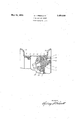
In the accompanying 15 forms a part of this specification and in which like characters of reference indicate like parts, there is shown a fragmentary cross section of a rim and mount constructed in accordance with the invention, as applied to a wheel of the steel disk type.
In carrying the invention into effect, there is provided a wheel body, and a roadside-demountable-rim provided with a continuous ring base seated on the periphery of the body and having two 'U-shaped inner peripheral ribs, one on either side of the central plane of wheel rotation, and also provided with two quick-detachable tire flanges anchored in said ribs. There is further rovided means entirely carried and retained by the body for.
' o eration. The terms split quick-detacha le tire flanges means split rings which are easily sprung in and out of position when changing a tire Without demounting the rim from a wheel body, also as a roadside operation.
In the best constructions contemplated, the rim includes a continuous ring base having wings supporting the tire flanges and having a tongue engaging a slot in the periphery of the wheel body whereby it. is driven when the wheel is a driver; the ring and tire flanges are rolled from flat stock and are uniform in thickness; and the means for bolding the rim on the body includes a nut fast to the inboard side of the body, a bolt workdrawing, which ing in said nut, a clamp carried by the bolt and engaging the body and the rim, and a device preventing separation of the nut, bolt and clam to prevent "loss of parts aflecting rim securlty when changing rims and tires by the roadside. These various parts may be varied in construction within the scope of the claims, for the particular construction selected to illustrate the invention is but one of I numerous possible concrete embodiments of the same. The invention, therefore, is not to be restricted to the precise details of the structure shown and described.
Referring to the drawing: 1 indicates a steel disk wheel body which is, provided with an integral conical peripheral rim seat 2' havlng a slot 3 preferablylocated at a point diametrically opposite the position of the valve stem of a tire carried by a rim on the body. 4 indicates a continuous ring forming the base of the rim and having inboard and outboard U-shaped inner peripheral ribs respectively marked 5 and 6, and having inboard and outboard wings respectively marked 7 and 8. The'inboard Wing 7.is provided with a bent tongue 9 projecting into the body slot 3 before referred to. When the Wheel is a driver, the engagement of a wall of the slot 3 with the tongue 9 results in driving the rim.
Quick-detachably engagingthe wings. 7 and 8, and anchored in the ribs 5 and 6, are two like split tire flanges 10, 10, which are held in anchored position by the non-stretchable beads of the tire on the rim, until the outer bead 1s purposely pushed off the outer tire flange 10 onto the mid-section of the ring 4, so that the outer flange 10 can be lifted out of the outer rib 6 torelease the tire from the rim. I
For the purpose of holding the rim in position on the body, there is provided a nut 11' secured to the inboard side of the body 1, and in this nut works a bolt 12 which carries a clamp 13 having a tape-red hole 14 through which the bolt passes. The clamp engages the body and the rim. A number, preferably an odd number, of like nuts, bolts and clamps are used, five for light cars and seven for heavycars, although only one is shown.
- To prevent separation of the nut, bolt and clamp, a spring ring is provided. This ring engages an annular groove in the bolt 12 adjacent its inboard end, and moves with the bolt.
To demou'nt the rim, it isunnecessary to disturb the clamp opposite the valve stem.
The other clamp bolts are backed out a few turns, untilthe rings 15 engage the nuts 11 and prevent furthermovement. The clamps will then be clear of the body shoulder, where it turns into the rim seat, and are turned 90 degrees on the bolts to clear the way for demounting therim. The lower part of the and clamp. v
4:. A t1re r m comprisin a continuous forpreventing. separation of said nut, bolt ring having inboard and out oard U-shaped inner peripheral ribs and wings extending from said ribs, the inboard rib and wing being adapted to engage a rim seat on a wheel body provided with a slot, and the inboard wing having a bent tongue adapted to en-' gage the slot. I
In testimony whereof, I have signed my name to this specification.
SYDNEY I. PRESCOTT;
rim'is then swung ofi the body and the whole 'rim lifted over the undisturbed clamp and thus entirely ofi the wheel. To mount a substitute rim, it is lifted over the undisturbed clamp with its tongue 9 engaging the body slot 3. Gravity then swings it into its proper place on the body. The released I clamps are then swung back into operative position, whereupon a fewturns of the bolts locks;the rim securely in proper position.
As a result of this construction, the oper- 'ation of changing rims and tires by the roadside is materially shortened and made easier, and cost is decreased. Rim security is insured because no parts of the rim fastening devices can be lost.
What is claimed is: 4 1. A tire mount, comprising awheel body having a rim seatand a slot in said seat, a'
continuous rin having inboard and outboard U-shape inner peripheral ribs and wings extending from said ribs, the inboard.
rib. and win engaging said seat and the in-- board wing aving a bent tongue projecting into said,slot, and means for demountably holding said ring on said seat.
' 2. A tire mount, comprisingh a wheel body having a rim seat and a slot in said seat, a
continuous ring having inboard and outboard U-shaped inner peripheral ribs and wings extending from said ribs, the inboard rib and wing engaging said seat and the inboard wing having a-bent "tongue projecting into said-slot, and means for demountably holding said ring on said seat, said seat being conical in form, and said inboard rib and wing engaging separated parts'of said seat.
3. A tire mount,comprising a wheel body having a rim seat and a slot in said seat, a
continuous ring having inboard and outboard U-shaped inner peripheral ribs and wings extending from said ribs, the inboard rib and wing engaging said seat and the in-
Priority Applications (1)
| Application Number | Priority Date | Filing Date | Title |
|---|---|---|---|
| US447127A US1859936A (en) | 1930-04-25 | 1930-04-25 | Tire rim and mount |
Applications Claiming Priority (1)
| Application Number | Priority Date | Filing Date | Title |
|---|---|---|---|
| US447127A US1859936A (en) | 1930-04-25 | 1930-04-25 | Tire rim and mount |
Publications (1)
| Publication Number | Publication Date |
|---|---|
| US1859936A true US1859936A (en) | 1932-05-24 |
Family
ID=23775088
Family Applications (1)
| Application Number | Title | Priority Date | Filing Date |
|---|---|---|---|
| US447127A Expired - Lifetime US1859936A (en) | 1930-04-25 | 1930-04-25 | Tire rim and mount |
Country Status (1)
| Country | Link |
|---|---|
| US (1) | US1859936A (en) |
Cited By (1)
| Publication number | Priority date | Publication date | Assignee | Title |
|---|---|---|---|---|
| US5035273A (en) * | 1987-09-21 | 1991-07-30 | Francesco Ruvio | Vehicle wheel rim device for mounting a first tire casing inwardly of a second tire casing, providing a safety emergency wheel device |
-
1930
- 1930-04-25 US US447127A patent/US1859936A/en not_active Expired - Lifetime
Cited By (2)
| Publication number | Priority date | Publication date | Assignee | Title |
|---|---|---|---|---|
| US5035273A (en) * | 1987-09-21 | 1991-07-30 | Francesco Ruvio | Vehicle wheel rim device for mounting a first tire casing inwardly of a second tire casing, providing a safety emergency wheel device |
| WO1993002873A1 (en) * | 1987-09-21 | 1993-02-18 | Francesco Ruvio | Vehicle wheel rim device for mounting a first tire casing inwardly of a second tire casing, providing a safety emergency wheel device |
Similar Documents
| Publication | Publication Date | Title |
|---|---|---|
| US2249568A (en) | Demountable rim | |
| US1859936A (en) | Tire rim and mount | |
| US2291217A (en) | Wheel and rim for vehicles | |
| US1368654A (en) | Vehicle-wheel | |
| US2563748A (en) | Bevel seat rim | |
| US1924970A (en) | Wheel | |
| US2021240A (en) | Tire rim | |
| US2261637A (en) | Rim mounting for dual wheels | |
| US1374106A (en) | perlman | |
| US1788862A (en) | Wheel assembly | |
| US1744761A (en) | Rim bolt | |
| US2360002A (en) | Brake drum | |
| US1863496A (en) | Vehicle wheel bolt | |
| US1928897A (en) | Truck wheel | |
| US1988509A (en) | Tire rim mount | |
| US1923811A (en) | Wheel for motor vehicles | |
| US2008330A (en) | Automobile wheel | |
| US1945277A (en) | Dual tired truck wheel | |
| US1878213A (en) | Metal wheel | |
| US1593886A (en) | Wheel and demountable rim | |
| US1819297A (en) | Demountable felly | |
| US1957690A (en) | Wheel rim | |
| US1936823A (en) | Rim construction | |
| US1639991A (en) | Demountable rim | |
| US1581639A (en) | Wheel |