US1859935A - Portable apparatus for spraying vegetables - Google Patents
Portable apparatus for spraying vegetables Download PDFInfo
- Publication number
- US1859935A US1859935A US385286A US38528629A US1859935A US 1859935 A US1859935 A US 1859935A US 385286 A US385286 A US 385286A US 38528629 A US38528629 A US 38528629A US 1859935 A US1859935 A US 1859935A
- Authority
- US
- United States
- Prior art keywords
- water
- vegetables
- vessel
- tank
- nozzle
- Prior art date
- Legal status (The legal status is an assumption and is not a legal conclusion. Google has not performed a legal analysis and makes no representation as to the accuracy of the status listed.)
- Expired - Lifetime
Links
- 235000013311 vegetables Nutrition 0.000 title description 12
- 238000005507 spraying Methods 0.000 title 1
- XLYOFNOQVPJJNP-UHFFFAOYSA-N water Substances O XLYOFNOQVPJJNP-UHFFFAOYSA-N 0.000 description 26
- 239000007921 spray Substances 0.000 description 11
- 238000001816 cooling Methods 0.000 description 8
- 239000007788 liquid Substances 0.000 description 7
- 210000002445 nipple Anatomy 0.000 description 4
- 239000003595 mist Substances 0.000 description 2
- 238000009428 plumbing Methods 0.000 description 2
- 230000001105 regulatory effect Effects 0.000 description 2
- 230000006978 adaptation Effects 0.000 description 1
- 235000013399 edible fruits Nutrition 0.000 description 1
- 238000004519 manufacturing process Methods 0.000 description 1
- 230000004048 modification Effects 0.000 description 1
- 238000012986 modification Methods 0.000 description 1
- 210000003813 thumb Anatomy 0.000 description 1
Images
Classifications
-
- B—PERFORMING OPERATIONS; TRANSPORTING
- B05—SPRAYING OR ATOMISING IN GENERAL; APPLYING FLUENT MATERIALS TO SURFACES, IN GENERAL
- B05B—SPRAYING APPARATUS; ATOMISING APPARATUS; NOZZLES
- B05B7/00—Spraying apparatus for discharge of liquids or other fluent materials from two or more sources, e.g. of liquid and air, of powder and gas
- B05B7/24—Spraying apparatus for discharge of liquids or other fluent materials from two or more sources, e.g. of liquid and air, of powder and gas with means, e.g. a container, for supplying liquid or other fluent material to a discharge device
- B05B7/2402—Apparatus to be carried on or by a person, e.g. by hand; Apparatus comprising containers fixed to the discharge device
- B05B7/247—Apparatus to be carried on or by a person, e.g. by hand; Apparatus comprising containers fixed to the discharge device a liquid being fed by gravity only from the container to the nozzle
-
- A—HUMAN NECESSITIES
- A47—FURNITURE; DOMESTIC ARTICLES OR APPLIANCES; COFFEE MILLS; SPICE MILLS; SUCTION CLEANERS IN GENERAL
- A47F—SPECIAL FURNITURE, FITTINGS, OR ACCESSORIES FOR SHOPS, STOREHOUSES, BARS, RESTAURANTS OR THE LIKE; PAYING COUNTERS
- A47F3/00—Show cases or show cabinets
- A47F3/001—Devices for lighting, humidifying, heating, ventilation
Definitions
- FIG. 1 A first figure.
- I Our invention relates to a portable means for creating and directing a vaporized spray of Water upon a vegetable rack or'thelike.
- the spray from our device being delivered'in a fine vaporized mist,is, quite largely evaporatedin'the air.
- Such evaporation-is attendedlloy a cooling of'the 'Fru'its,'"vegetables 'and cut flowers are preserved longer under the vaporized than 'under'the coarser spray.
- Fig, 2 is a fragmentary elevational view an of the spraynozzleandfwater trap asflde- "appended, and illustrated in theaccompany signed to hang froma support.”
- positioning means 10 such as athumbscrew 1 a or the like'is provided upon the lcwer por e tion of the said sleeve 7 'in suchamariner as I to contact the said standard fsandfmaintain 6 said sleeve 7 'i'n'a desired position'thereupon;
- Patent is; Y
- said er exterior to and integral with said tank and maintaining the waterat a desired depth connected thereto by a first tube, an air nozwlthm sald vesse and means for supplymg zle disposed at an upward angle through a compr ss d to Sald IlOZZle- Y 1 wall of said container, said nozzle connected to said air compressor bya second tube ex tending through said upstanding and saiddownstan'ding portions, said first tube hav- 7 ing a needle valve for regulating the flow of said liquid from said tank tosaidcon-.
- An atomizer for cooling vegetables and the like having in combination, a vessel having its entire top open,'an air nozzle rigidly disposed at an upward angle within said vessel, means for supplying air under presliquid at a level slightly above the tip of said nozzle.
- an atomizer for cooling vegetables and the like the combination with a water containing vessel having its entire top open, of an air nozzle disposed in said vessel at an oblique angle to and with its tip slightly beneath the surface of said water, said nozzle adapted to form a mistof said water, and to force said mist outwardly over the edge of said vessel.
Landscapes
- Special Spraying Apparatus (AREA)
Description
y 1932- L. c. POTTS ET AL PORTABLE APRARATUS FOR SPRAYING' VEGETABLES Filed Aug. 12, 1929 FF till/Ill: villi/II) vlIll/lI/Il/IIILiI/Ill T 7" lllllll/II/IlI/I'llf'ln III/I'l/l' lll F FIG. .2.
FIG.
A TTORNE Y Patented May 24; 1932 f UNITE YS A ES PATENT hosts 0. POTTS AND OLIVER '1 BOMINE oFonIlA o A cIiii,.roi LAnoMAf m a rORi ABLE APPARATUS- FOR SlfRAY IfiG l Application filed August 12', 1929. saga No. 385336,;
I Our invention relates to a portable means for creating and directing a vaporized spray of Water upon a vegetable rack or'thelike.
The objects of our inventionare to provide 5 a device of this class Which isneyv, novel,
' practical and of utility; which Willbe serviiceable prim'arily to green grocers, florists,
and the like; whichvvill. create a vaporized mist-like spray of Water for the coolingfof' vegetables, fruits or cut flowers, and which will direct such spray as -desired a device which will be portable; vvhichmay readily be moved from place to place in or about a store; which in its preferred embodiment will contain its own Water supply which may lee furnished by buckets instead of a water supply system; ,Which' will eliminatefihe plumbing and Water pipesincident to usual sprays; Which'vvill. be-adjustable invheight in orderthat shelves or trays of varying heights may be sprayedywhich vvill use but asmall quantity of Water {which will be relatively inexpensive. in manufacture and in operation; which Will be simple and durable;
which will-prevent the vegetables and "the like from becoming Water soaked, and becoming ruined thereby; which will be eflicientin accomplishing all the purposes for" which it 'is'intended. i
In so far-as applicants know or can asceritain there are now no. portable vegetable sprays available Which maybe moved from place to place within' or without'a store "and i so operated, free from attachment'to awater tap. Such tapsare not alwaysa'vailable and even when available..are not'alwa'ys located at pointsbest' adapted .to usef with the usual spray." Usual device s provide a relatively heavy spray of water.
Being self .contai ed, our portable spray may be readily positioned adj acent' a vege= table rack or flower standand moved as desired; No plumbing or vvater pipes'are required. The spray from our devicebeing delivered'in a fine vaporized mist,is, quite largely evaporatedin'the air. Such evaporation-is attendedlloy a cooling of'the 'Fru'its,'"vegetables 'and cut flowers are preserved longer under the vaporized than 'under'the coarser spray.
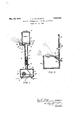
'Th vvater tank 9 rigidly sec ijii'ed ijn a leak- "proof manner to-thesaidfbase 8, rises therefromin such form'as may; be desired andjis- I sists in the constructiom n ovel?features,f and combination of, parts hereinafter more fully described, pointed out in the claims'hereto ing one-sheet'drawings'fof which l V j Figure l is an elevational sectional View of one embodiment of the device; 1
Fig, 2 is a fragmentary elevational view an of the spraynozzleandfwater trap asflde- "appended, and illustrated in theaccompany signed to hang froma support."
parts in all the figures.
I Like characters of reference d s t k x It is understood.that gvarious changes inffi V v the form, proportion, size, shape, weight and other detail'sofconstruction, Within the scope of our inventionmay belresorted to Without departing from the spiritor broad principles of our inventionand withoutsacrificing any r j of the advantages thereof; and it is'also understood that the drawingsare, to be 'interpreted asfbeing illustrative and i notfrestrictive.
plurality of caster heels 3. iThe metalof the' top of said housing is extended upwardly 380 I g V to forma 'holloW-standardfe' which has'an open bottom 5 and opentop 6. 1A vertically adjustable sleeve: "(descends from thejba's'e 8 of the water-tank 9 thereabove an'd' slidably envelopes partially the said'standard 4. l A
positioning means 10 such as athumbscrew 1 a or the like'is provided upon the lcwer por e tion of the said sleeve 7 'in suchamariner as I to contact the said standard fsandfmaintain 6 said sleeve 7 'i'n'a desired position'thereupon;
provided lWllJh a false botton i i311 adjacent the said basejand with aremo'vable closed, top
perforation'an'd thereinydownvvardly extendhe th n l lll -li 'iB fii' n s fa bottom 11 and said tankbasef8, said nipple One practical embodiment of the invention as illustratedin the drawingscomprisesjf V p A boxlike housing lyof sheet Inetalor the.
like, having a door 2', andemounted upon a i 5 j 12; saidfa'lse bottom 11 isvivatertight and is provided adjacent one side; With'a threaded I enters the T of a needle valve 14, which is mannerv upon the aid base;8.1Said trap is designed to hold a small uantity of Water and has an open Sui trap '18 and 9 are connected only through the said tubelfi.
Within the said housin-g'fl and rigidly se enrerl t it floor 2 is esmall el-r ee iezne .22 o k own'meke operetiv lyeo neete to a usu lyllriving elee rie m urn" 23 T e ette is e nneet d by u ua mea s not showt aseur e o e e ien s pplyr From '1 l mpressor 22, a exible ub 25' leads pwa dly through th said st n a d ll the leeVe-l the base 8 Wh re it e nects 1n a leak proofmanner with a meta nipple 2-0 fiei nipple ente s th ap 18 vet u upwa d eng e'th oegh t e side wil of h said k, 94 thr ugh a perforatienin the letter be ow the stud talse bottom Withinthe trap 18 said nipple is capped with a let nozzle 2- th tip e'fwhieh is sligh ly bel thel vel' t the d walls of aid trap.
, I11 operation our portabl spray-will be positio e as desi e adg eent a [v getabl reckon the llke- The thumb cre 10 ill be loo eneclaml the tank 9 raised r lowered to the des red height Serewlll will he he so tlght ned- Thetenk 9 will hesuup ied with ate nd he ne dl ml e 4 wi he open-eel by the control 15, permitting the Water trap 18 to fil to e evel ery sl ghtly, a ove t e orifieeof theeir jet noizl Current wil h applied toithe m t r 24s Compressor 22 ill force a .eol mn f air thr ug th tub 2 and jet n l 25\ The air pressu e thus lelive ed will f reibly'propel smell quant ties of Wat r roken up'lnto e fin vapo zed mlstfllke spray upwe dly end outwa dly ll he d ree ion o t to ee and moisten the pr ductsiupon the adli n reels e Il ezflo t w tet from taiikvl lii eees e'ry tor'etein the esire level in Water rap 18, .l.l be regulated by he needle valve lep e- Ylfill ly filll'lbedl V Becau e f the e t emefineuess ofthespray eveloped by our devis much of the m will beehs rh d lay-the e i e t atmo p e, the e y cooling same to ama ke egree The residue will be deposi d upo the v g tah es or f uits upon h us rack sam 7 Will e co led and moistenedyret r t I water-so ked; Being so c oled and moistene $11, 11 pmfllietslrete n the fre h e s mush lene rth n when m ely d ene e l l'figurekgi lustr tes our nezzl 2 ithin a trap 18Whioh is provided With a means such as the perforation shown at. Q71OT-SHSI36D- sion. The drip from a Water pipe 28 is permitted to fall into the said trap 18 and the tank 9 is thus eliminated. In this embodiment the motor and compressor are positioned at eon n elit p nt n t shown- Qbviously, theinvention is suseeptible of embodiment informs other than that Which Sis illustrated in the accompanying drawings and described herein, and appliealete, for the uses and purposes other than as detailed, and we therefore coasider as our own all such modifications and adaptations and other uses of the torm'of the device herein described as feix y tall Within thes'oope otourin en l-l e-y ug thus an: inventiont What is olaa med and desire tobe eeul ed Joy-Let,-
Patent, is; Y
1.! de ic as des ibed; emb dying a hollow whee ed base member havi g a ollow upstan ing po tion, a liquid supply tankh v- 7' ing a hol o downsten ing po tien, saidupsta ing, and sa d o nstending ,ortio l teles oping and re at vely adjustah. verti t tally, ah open topp d eon alner exterior to a d i egral-With said tank and, onnecte thereto by a rst tube; an. ai nozz e dis. osed at n upwa ang e, th ough a wall 0, said eo ame said nozzle connected by a sesendu e Within said ups an ing and said clo nst n ing po tions to an air supp y ithin said ase ember, s id first tube havingva ve o teguleting t sewer said. liquid from s i tank to said-p tai erl aud tor me nte ning he l vel of said liquid in said of aid nozzle.
2.- Asprefi as described, in ombination, a
hollow, wheeled basememberheving ah llow upstendmg po tion, a l qu d supply tank having a hollow downs nding perm-on, said upstandmg and .S ud downst ndmg portions telescoping and relatlvelyi adjustable vertiea ly, enop n topped container e terior o andv integral th said tank and con ected ther to bye fir t tube, .eneix noz Z1e' isposed at eetpW rgl angle through afiwall oil-said eontemer, Silld nozzle connected by a second t b :iyithln sald z lptfilldillgflnd said do n-' standing p tlons to" an airsupp y within saidbase memhen'se d firs tubehev ng e Iee tainer at ape int slightly above the tip 7 al e f r r gulating the flow'of. said-liquid i from' said tank to said I e0ntaintn and for main aining t e l el of said. l quid in said container at a point slightly above the tip of saidnozzle- 3! In pray, he ombinetion' 'witlilla hee ed ba me ber o s ng. a" otor: and
an a r ompressor.,1 f e ho o upstan l ng portion integral with said basemember, a liqid supply tank having a hollowldownstandmglportlon, sa d upstanding and said downt ge i g portions telescoping and re atively ad ustable vertically, an open topped'eontainsure to said nozzle, and means for supplying V a liquid to said vessel andmaintaining. said er exterior to and integral with said tank and maintaining the waterat a desired depth connected thereto by a first tube, an air nozwlthm sald vesse and means for supplymg zle disposed at an upward angle through a compr ss d to Sald IlOZZle- Y 1 wall of said container, said nozzle connected to said air compressor bya second tube ex tending through said upstanding and saiddownstan'ding portions, said first tube hav- 7 ing a needle valve for regulating the flow of said liquid from said tank tosaidcon-.
tainer and for maintaining the level'of said v I liquid at a point in said container slightly above the tip of said nozzle. 7 W
4. An atomizer for cooling vegetables and the like, having in combination, a vessel having its entire top open,'an air nozzle rigidly disposed at an upward angle within said vessel, means for supplying air under presliquid at a level slightly above the tip of said nozzle.
5. In an atomizer for cooling vegetables and the like, the combination witha water containing vesselhaving its entire top open,
of an air nozzle disposed in said vesselat an oblique angle to and with its tip slightly beneath the surface of said water.
6. In an atomizer for cooling vegetables and the like, the combination with a water containing vessel having its entire top open, of an air nozzle disposed in said vessel at an oblique angle to and with its tip slightly beneath the surface of said water, said nozzle adapted to form a mistof said water, and to force said mist outwardly over the edge of said vessel.
7. In an atomizer for. cooling vegetables and the like, the combination of a water containing vesselhaving its entire top open, with an air nozzle disposed in said vessel with its tip slightly below and at an angle to the surface of the water. i g 8. In an atomizer for cooling vegetables and the like, the combination of a water containing vessel having its entire top open, and
slightly below and at an upwardlyinclined angle to the surface of the water, means for supplying water to said vessel, and means a for maintaining the water at a desired depth withinsaid vessel.
10. In an atomizer for cooling vegetables and the like, the combinationof a water containing vessel having its entire top open, an
air nozzle disposed in said vessel with its tip slightly below and at an upwardly inclined 1 angle to the surface .ofthe water, means for j supplying water to said vessel, means for
Priority Applications (1)
| Application Number | Priority Date | Filing Date | Title |
|---|---|---|---|
| US385286A US1859935A (en) | 1929-08-12 | 1929-08-12 | Portable apparatus for spraying vegetables |
Applications Claiming Priority (1)
| Application Number | Priority Date | Filing Date | Title |
|---|---|---|---|
| US385286A US1859935A (en) | 1929-08-12 | 1929-08-12 | Portable apparatus for spraying vegetables |
Publications (1)
| Publication Number | Publication Date |
|---|---|
| US1859935A true US1859935A (en) | 1932-05-24 |
Family
ID=23520783
Family Applications (1)
| Application Number | Title | Priority Date | Filing Date |
|---|---|---|---|
| US385286A Expired - Lifetime US1859935A (en) | 1929-08-12 | 1929-08-12 | Portable apparatus for spraying vegetables |
Country Status (1)
| Country | Link |
|---|---|
| US (1) | US1859935A (en) |
Cited By (5)
| Publication number | Priority date | Publication date | Assignee | Title |
|---|---|---|---|---|
| US3421692A (en) * | 1966-12-29 | 1969-01-14 | Robert S Babington | Method of atomizing liquids in a mono-dispersed spray |
| US3421699A (en) * | 1966-12-29 | 1969-01-14 | Robert S Babington | Apparatus for spraying liquids in mono-dispersed form |
| US3472455A (en) * | 1967-06-20 | 1969-10-14 | Paramedical Research & Dev Cor | Aerosol apparatus and method of generating micronic size aerosol particles |
| US3864326A (en) * | 1972-05-22 | 1975-02-04 | Robert S Babington | Spraying devices, in particular nebulizing devices |
| USRE30285E (en) * | 1972-05-22 | 1980-05-27 | Spraying devices, in particular nebulizing devices |
-
1929
- 1929-08-12 US US385286A patent/US1859935A/en not_active Expired - Lifetime
Cited By (5)
| Publication number | Priority date | Publication date | Assignee | Title |
|---|---|---|---|---|
| US3421692A (en) * | 1966-12-29 | 1969-01-14 | Robert S Babington | Method of atomizing liquids in a mono-dispersed spray |
| US3421699A (en) * | 1966-12-29 | 1969-01-14 | Robert S Babington | Apparatus for spraying liquids in mono-dispersed form |
| US3472455A (en) * | 1967-06-20 | 1969-10-14 | Paramedical Research & Dev Cor | Aerosol apparatus and method of generating micronic size aerosol particles |
| US3864326A (en) * | 1972-05-22 | 1975-02-04 | Robert S Babington | Spraying devices, in particular nebulizing devices |
| USRE30285E (en) * | 1972-05-22 | 1980-05-27 | Spraying devices, in particular nebulizing devices |
Similar Documents
| Publication | Publication Date | Title |
|---|---|---|
| US1859935A (en) | Portable apparatus for spraying vegetables | |
| US2153156A (en) | Fluid dispensing apparatus | |
| US1911367A (en) | Spraying device | |
| US4173295A (en) | Barrel dispensing support | |
| US2655407A (en) | Self-filling, hand-operated atomizer or spraying device | |
| US878750A (en) | Liquid-soap dispenser. | |
| US2543294A (en) | Nozzle for mixing liquids | |
| WO2014037749A1 (en) | Spray gun washing apparatus and method | |
| US1846098A (en) | Soap and water mixer | |
| US984187A (en) | Apparatus for dispensing cleaning fluids. | |
| US9745735B2 (en) | Intake nozzle for suction hose | |
| US156923A (en) | Improvement in soap-bubble toys | |
| US765815A (en) | Liquid delivering and measuring device. | |
| US563829A (en) | Sprayer | |
| US2699927A (en) | Humidifier | |
| US547048A (en) | Oil-can | |
| WO2024196739A3 (en) | Improved table top dispenser | |
| US742113A (en) | Oil or liquid spraying or ejecting apparatus. | |
| US493123A (en) | Condenser | |
| US1680983A (en) | Combined liquid container and sprayer | |
| US175039A (en) | Improvement in fire-extinguishers and window-washers | |
| US167790A (en) | Improvement in flower-pots | |
| US618532A (en) | Self-measuring apparatus for dispensing liquids | |
| CN117981740B (en) | Insect-proof spraying device | |
| KR102485746B1 (en) | Sprayer |