US1859933A - Liquid level indicator - Google Patents
Liquid level indicator Download PDFInfo
- Publication number
- US1859933A US1859933A US405768A US40576829A US1859933A US 1859933 A US1859933 A US 1859933A US 405768 A US405768 A US 405768A US 40576829 A US40576829 A US 40576829A US 1859933 A US1859933 A US 1859933A
- Authority
- US
- United States
- Prior art keywords
- pressure
- floats
- liquid
- stem
- tank
- Prior art date
- Legal status (The legal status is an assumption and is not a legal conclusion. Google has not performed a legal analysis and makes no representation as to the accuracy of the status listed.)
- Expired - Lifetime
Links
- 239000007788 liquid Substances 0.000 title description 19
- OKTJSMMVPCPJKN-UHFFFAOYSA-N Carbon Chemical compound [C] OKTJSMMVPCPJKN-UHFFFAOYSA-N 0.000 description 9
- 229910052799 carbon Inorganic materials 0.000 description 4
- 239000000463 material Substances 0.000 description 4
- 239000002184 metal Substances 0.000 description 3
- VYPSYNLAJGMNEJ-UHFFFAOYSA-N Silicium dioxide Chemical compound O=[Si]=O VYPSYNLAJGMNEJ-UHFFFAOYSA-N 0.000 description 2
- 241000209761 Avena Species 0.000 description 1
- 235000007319 Avena orientalis Nutrition 0.000 description 1
- 102100035683 Axin-2 Human genes 0.000 description 1
- 101700047552 Axin-2 Proteins 0.000 description 1
- 240000007182 Ochroma pyramidale Species 0.000 description 1
- 239000004020 conductor Substances 0.000 description 1
- 238000010276 construction Methods 0.000 description 1
- 239000007799 cork Substances 0.000 description 1
- 238000006073 displacement reaction Methods 0.000 description 1
- 230000000694 effects Effects 0.000 description 1
- 239000008187 granular material Substances 0.000 description 1
- 229910002804 graphite Inorganic materials 0.000 description 1
- 239000010439 graphite Substances 0.000 description 1
- 230000002706 hydrostatic effect Effects 0.000 description 1
- 238000009413 insulation Methods 0.000 description 1
- 238000000034 method Methods 0.000 description 1
- 238000009877 rendering Methods 0.000 description 1
- 229910010271 silicon carbide Inorganic materials 0.000 description 1
- 239000000377 silicon dioxide Substances 0.000 description 1
Images
Classifications
-
- G—PHYSICS
- G01—MEASURING; TESTING
- G01F—MEASURING VOLUME, VOLUME FLOW, MASS FLOW OR LIQUID LEVEL; METERING BY VOLUME
- G01F23/00—Indicating or measuring liquid level or level of fluent solid material, e.g. indicating in terms of volume or indicating by means of an alarm
- G01F23/30—Indicating or measuring liquid level or level of fluent solid material, e.g. indicating in terms of volume or indicating by means of an alarm by floats
- G01F23/56—Indicating or measuring liquid level or level of fluent solid material, e.g. indicating in terms of volume or indicating by means of an alarm by floats using elements rigidly fixed to, and rectilinearly moving with, the floats as transmission elements
- G01F23/60—Indicating or measuring liquid level or level of fluent solid material, e.g. indicating in terms of volume or indicating by means of an alarm by floats using elements rigidly fixed to, and rectilinearly moving with, the floats as transmission elements using electrically actuated indicating means
Definitions
- My invention relates to liquid level indicators and has a particular reference to indicators using floats in connection with variable electrical resistance, the current variations being proportional to the hydrostatic 5.
- a powdered or granulated conductin material such as carbon or graphite
- a suitable container between two electrodes, one of which forms a flexible diaphragm.
- This diaphragm is acted upon by a series of floats, each float becoming operative at a certain height of the liquid in the tank where it is desired to measurethe' 15 height of this liquid.
- the pressure on the resistor is proportional to the number of floats submerged or to the height of the liquid.
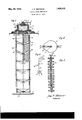
- Fig. 1 is a sectional elevation of my indicator
- Fig. 2 is a plan view of a float showing also method of its support
- Fig. 3 is a 25 modified construction of the floats
- Fig. 4 is a diagrammatic view showing electrical connections.
- My indicator consists of a case or housing 1 lined with an insulation 2 inside.
- a ter- 30 minal screw 3 is fastened in the wall of the case by a nut 4 and has metal washers 5 and 6. It is insulated by an insulating washer 7 and a bushing 8.
- a terminal 9 of an insulated wire 10 is clam ed with a nut 11.
- the case 1 is closed un erneath with a flexible diaphragm 12 which is made preferably of a thin soft metal sheet and is corrugated to allow for a greater flexibility. It is attached to a bottom plate 13 which is grounded or otherwise forms a part of the electric circuit.
- the s ace inside of the case 1 is filled with a pow ered and granulated (or both) conducting material, preferably carbon.
- the diaphragm 12 is covered inside with an insulating sheet 14 made of a flexible material and provided with a central aperture 15 so as to increase the efiective resistance of the carbon powder in the case.
- the carbon powder 50 16 can be mixed with some insulating or highly resistant'material, such as carborundum, silica etc. a
- the case 1 is attached to the top of a tank 17 in which it is desired to measure the height of the liquid.
- the bottom plate 13 has a tubular projection 18 closed with a cap 19 with a central aperture for a float stem 20.
- the .upper end of this stem has a metal disc 21 adapted to press against the diaphragm 12.
- soft and resilient washer 22 is placed between the disc 21' and the diaphragm 12 in order to distribute the pressure from the stem evenly over the diaphragm.
- the washer 22 can be made of rubber or felt.
- the chamber formed by the diaphragm and the cap 19 is of a suflicient size to permit a certain freedom of verticalmovement for the stem with the disc 21 and washer 22.
- the lower end of the stem is slidably supported in the bottom bar 23 attached with its ends to guiding rods 24 and 25 fastened with their upper ends-to the sides of the case 1.
- the rod 24 has a hinge 26 at the top so as to facilitate the assembling of the floats 27.
- the rods 2e and 25 have supporting washers or shoulders 28 adapted to support the floats 27 at regular intervals from. the bottom to the-top of the tank 17. They are provided with slots 29 loosely fitting over the stem 20.
- the stem 20 has washers or bushin s 30 so arranged that they do not touch the oats in any positions of the stem 20 when the floats rest on the washers 28.
- the floats are made smaller than the distance between consecutive washers 28 so that they can be moved up and down between these washers.
- the floats can be made of any suitable material, such as cork, balsa wood, or they can be made hollow to increase their buoyancy.
- the carbon resistor in the cage 1 forms an electric circuit with the wires 10 and 31 for a battery 32.
- the strength of the current is measured by a suitable electric meter 33 which can be an ordinary milliammeter or galvanometer calibrated in units of height of the liquid in the tank or in units of volumetric content.
- a switch 34 may be provided in order to disconnect the battery when the indicator is not used. This switch can be interconnected with the ordinary ignition switch on an automobile so that the indicator will operate only when the ignition switch is closed.
- the meter 33 is adjusted to indicate zero when there is no liquid in the tank.
- the spring of the meter pointer can be set so that the pointerwill be pressed against the stop at the zero mark for the current which passes through the system when there is no pressure applied to the resistor, and will move upon the dial only for stronger currents.
- the volumetric compressibility of the carbon powder 16 being insignificant as it is tightly packed during its assembling, the float will stop in its raised position continuing to press the stem against the diaphragm, without touching the next washers 28.
- the float When more liquid is poured in the tank the float will gradually increase its pressure until it is fully covered by liquid, after that its pressure will remain constant. With further rise of the liquid level the next float will become operative, its pressure adding to the pressure from the first float. In order to obtain a gradual and continuous increase in pressure the floats are made of a. concaveconvex shape as shown, so that before the first float is fully submerged, the next float begins to act.
- Fig. 3 shows an arrangement in which the bulk of the floats progressively increases from the ends to the middle so that, for the same height of liquid, the pressure at the ends is lighter than in the middle. This permits the use of a meter with equal divisions on its dial for use with oval or round tanks.
- the voltage of an ordinary storage battery as used on automobiles is sufiiciently constant for ordinary purposes. If very accurate readings are wanted, however, it is possible to provide some of the well known means for rendering the meter readings independent of the voltage variations, for instance, by'introducing a Wheatstone bridge.
- a liquid level indicator In a liquid level indicator, the combination with guiding bars adapted to be supported in a tank, of a rod slidably supported between said guiding bars, a plurality of projcctions on said guiding bars, a pluralit of floats slidably supported between said ars and adapted to rest on said projections, said floats being adapted to slide over said rod, a
Landscapes
- Physics & Mathematics (AREA)
- Fluid Mechanics (AREA)
- General Physics & Mathematics (AREA)
- Level Indicators Using A Float (AREA)
Description
May 24, 1932 J. P. NIKONOW 1,359,933
LIQUID LEVEL INDICATOR Filed Nov.8, 1929 INVENTOR Patented Ma, 24, .1932
UNITED STATES JOHN P. NIKONOW, NEW YORK, N. Y.
mourn LEVEL mnrca'ron Application filed November 8, 1929. Serial No. 405,768.
My invention relates to liquid level indicators and has a particular reference to indicators using floats in connection with variable electrical resistance, the current variations being proportional to the hydrostatic 5.
pressure.
- For this purpose I use a powdered or granulated conductin material, such as carbon or graphite, place in a suitable container between two electrodes, one of which forms a flexible diaphragm. This diaphragm is acted upon by a series of floats, each float becoming operative at a certain height of the liquid in the tank where it is desired to measurethe' 15 height of this liquid. With this arrangement the pressure on the resistor is proportional to the number of floats submerged or to the height of the liquid.
My invention is more fully described in go the accompanying specification and drawings in whic I Fig. 1 is a sectional elevation of my indicator, Fig. 2 is a plan view of a float showing also method of its support, Fig. 3 is a 25 modified construction of the floats, and Fig. 4 is a diagrammatic view showing electrical connections. Y
My indicator consists of a case or housing 1 lined with an insulation 2 inside. A ter- 30 minal screw 3 is fastened in the wall of the case by a nut 4 and has metal washers 5 and 6. It is insulated by an insulating washer 7 and a bushing 8. A terminal 9 of an insulated wire 10 is clam ed with a nut 11. The case 1 is closed un erneath with a flexible diaphragm 12 which is made preferably of a thin soft metal sheet and is corrugated to allow for a greater flexibility. It is attached to a bottom plate 13 which is grounded or otherwise forms a part of the electric circuit. The s ace inside of the case 1 is filled with a pow ered and granulated (or both) conducting material, preferably carbon. The diaphragm 12 is covered inside with an insulating sheet 14 made of a flexible material and provided with a central aperture 15 so as to increase the efiective resistance of the carbon powder in the case.
For the same purpose the carbon powder 50 16 can be mixed with some insulating or highly resistant'material, such as carborundum, silica etc. a
The case 1 is attached to the top of a tank 17 in which it is desired to measure the height of the liquid. The bottom plate 13 has a tubular projection 18 closed with a cap 19 with a central aperture for a float stem 20. The .upper end of this stem has a metal disc 21 adapted to press against the diaphragm 12. soft and resilient washer 22 is placed between the disc 21' and the diaphragm 12 in order to distribute the pressure from the stem evenly over the diaphragm. The washer 22 can be made of rubber or felt. The chamber formed by the diaphragm and the cap 19 is of a suflicient size to permit a certain freedom of verticalmovement for the stem with the disc 21 and washer 22.
v The lower end of the stem is slidably supported in the bottom bar 23 attached with its ends to guiding rods 24 and 25 fastened with their upper ends-to the sides of the case 1. The rod 24 has a hinge 26 at the top so as to facilitate the assembling of the floats 27.
The rods 2e and 25 have supporting washers or shoulders 28 adapted to support the floats 27 at regular intervals from. the bottom to the-top of the tank 17. They are provided with slots 29 loosely fitting over the stem 20.
The stem 20 has washers or bushin s 30 so arranged that they do not touch the oats in any positions of the stem 20 when the floats rest on the washers 28.
The floats are made smaller than the distance between consecutive washers 28 so that they can be moved up and down between these washers.
The floats can be made of any suitable material, such as cork, balsa wood, or they can be made hollow to increase their buoyancy.
The carbon resistor in the cage 1 forms an electric circuit with the wires 10 and 31 for a battery 32. The strength of the current is measured by a suitable electric meter 33 which can be an ordinary milliammeter or galvanometer calibrated in units of height of the liquid in the tank or in units of volumetric content.
A switch 34 may be provided in order to disconnect the battery when the indicator is not used. This switch can be interconnected with the ordinary ignition switch on an automobile so that the indicator will operate only when the ignition switch is closed.
The operation of my indicator is as follows.
The meter 33 is adjusted to indicate zero when there is no liquid in the tank. For this purpose the spring of the meter pointer can be set so that the pointerwill be pressed against the stop at the zero mark for the current which passes through the system when there is no pressure applied to the resistor, and will move upon the dial only for stronger currents.
With no liquid in the tank all floats rest on the washers 28 so that the stem 20 hangs free supported on the bar23 or on the plate 19 with its disc 21.
\Vhen the liquid is poured in the tank the first or bottom float 27 will rise on it pressing against the washer 30 and pushing the stem 20 up. The stem accordingly will exert a pressure on the diaphragm 12 through the elastic washer 22. Under this pressure the resistance of the carbon powder 16 will be lowered, a stronger current will flow causing the pointer of the meter 33 to move.
The volumetric compressibility of the carbon powder 16 being insignificant as it is tightly packed during its assembling, the float will stop in its raised position continuing to press the stem against the diaphragm, without touching the next washers 28.
When more liquid is poured in the tank the float will gradually increase its pressure until it is fully covered by liquid, after that its pressure will remain constant. With further rise of the liquid level the next float will become operative, its pressure adding to the pressure from the first float. In order to obtain a gradual and continuous increase in pressure the floats are made of a. concaveconvex shape as shown, so that before the first float is fully submerged, the next float begins to act.
The maximum pressure from each float is proportional to its buoyancy or displacement. It. is possible therefore to vary this pressure by changing the shape of the floats. Fig. 3 shows an arrangement in which the bulk of the floats progressively increases from the ends to the middle so that, for the same height of liquid, the pressure at the ends is lighter than in the middle. This permits the use of a meter with equal divisions on its dial for use with oval or round tanks.
In order to equalize the pressure in the tank and in the case 1 a pipe 35 is inserted in the case from the plate 13 with a number of small holes. Any pressure or vacuum in the tank, therefore, is also communicated to the inside space in the case 1 between the granules of the carbon 16 thereby relieving the diaphragm from the effects of this pressure.
The voltage of an ordinary storage battery as used on automobiles is sufiiciently constant for ordinary purposes. If very accurate readings are wanted, however, it is possible to provide some of the well known means for rendering the meter readings independent of the voltage variations, for instance, by'introducing a Wheatstone bridge.
I claim as my invention:
In a liquid level indicator, the combination with guiding bars adapted to be supported in a tank, of a rod slidably supported between said guiding bars, a plurality of projcctions on said guiding bars, a pluralit of floats slidably supported between said ars and adapted to rest on said projections, said floats being adapted to slide over said rod, a
plurality ofprojections on said rod adapted to be actuated by said floats when said floats are successively raised by a liquid in said tank, a pressure actuated element, the end of said rod being adapted to engage said pressure element, said floats being adapted to transmit pressure to said element through said projections of said rod, said pressure being proportional to the number of floats in contact with said liquid, and means to measure the height of said liquid by measuring the variable pressure on said element.
In testimony whereof I aflix my signature.
JOHN P. NIKONOW.
Priority Applications (1)
| Application Number | Priority Date | Filing Date | Title |
|---|---|---|---|
| US405768A US1859933A (en) | 1929-11-08 | 1929-11-08 | Liquid level indicator |
Applications Claiming Priority (1)
| Application Number | Priority Date | Filing Date | Title |
|---|---|---|---|
| US405768A US1859933A (en) | 1929-11-08 | 1929-11-08 | Liquid level indicator |
Publications (1)
| Publication Number | Publication Date |
|---|---|
| US1859933A true US1859933A (en) | 1932-05-24 |
Family
ID=23605144
Family Applications (1)
| Application Number | Title | Priority Date | Filing Date |
|---|---|---|---|
| US405768A Expired - Lifetime US1859933A (en) | 1929-11-08 | 1929-11-08 | Liquid level indicator |
Country Status (1)
| Country | Link |
|---|---|
| US (1) | US1859933A (en) |
Cited By (5)
| Publication number | Priority date | Publication date | Assignee | Title |
|---|---|---|---|---|
| US2791907A (en) * | 1954-05-19 | 1957-05-14 | Griner | Device for indicating stages of fluid depth of water in wells |
| US4368640A (en) * | 1981-01-29 | 1983-01-18 | The United States Of America As Represented By The United States Department Of Energy | Liquid level sensing device |
| US5103673A (en) * | 1989-09-25 | 1992-04-14 | Moriyama Kogyo Kabushiki Kaisha | Fluid level indicator for small watercraft |
| US5586466A (en) * | 1993-12-16 | 1996-12-24 | Steiner; George A. | Non-slip sleeve for float level sensor shaft |
| US6481277B1 (en) * | 2001-01-23 | 2002-11-19 | Advanced Micro Devices, Inc. | Temperature control unit and sight glass |
-
1929
- 1929-11-08 US US405768A patent/US1859933A/en not_active Expired - Lifetime
Cited By (5)
| Publication number | Priority date | Publication date | Assignee | Title |
|---|---|---|---|---|
| US2791907A (en) * | 1954-05-19 | 1957-05-14 | Griner | Device for indicating stages of fluid depth of water in wells |
| US4368640A (en) * | 1981-01-29 | 1983-01-18 | The United States Of America As Represented By The United States Department Of Energy | Liquid level sensing device |
| US5103673A (en) * | 1989-09-25 | 1992-04-14 | Moriyama Kogyo Kabushiki Kaisha | Fluid level indicator for small watercraft |
| US5586466A (en) * | 1993-12-16 | 1996-12-24 | Steiner; George A. | Non-slip sleeve for float level sensor shaft |
| US6481277B1 (en) * | 2001-01-23 | 2002-11-19 | Advanced Micro Devices, Inc. | Temperature control unit and sight glass |
Similar Documents
| Publication | Publication Date | Title |
|---|---|---|
| US4169377A (en) | Quantity sensing system for a container | |
| US2338811A (en) | Level indicator | |
| US2472214A (en) | Pressure responsive electrical resistor | |
| US3164023A (en) | Motion sensing transducer | |
| US2505936A (en) | Temperature compensated conductivity cell electrode | |
| US4131773A (en) | Apparatus for detecting presence of oil in a body of water | |
| SE425699B (en) | DEVICE FOR Saturation of the Standing Height of Electrically Conductive Liquids | |
| US2622442A (en) | Apparatus for measuring liquid levels | |
| US3269180A (en) | Capacitive electrode for flow measurement in open channels | |
| US1859933A (en) | Liquid level indicator | |
| US3555904A (en) | Fluid quantity indicating system | |
| US2894390A (en) | Liquid level sensing means | |
| US2541576A (en) | Apparatus for determining fluent level | |
| US2589714A (en) | Electrical water gauge | |
| US3910118A (en) | Probe for controlling the level of electrically conductive liquids | |
| US2743340A (en) | Electrical resistor device | |
| US1532871A (en) | Level-indicating device | |
| US2213485A (en) | Liquid level indicator | |
| US3805613A (en) | Liquid level indicator | |
| US2434425A (en) | Apparatus for the gauging of liquids | |
| US3350940A (en) | Level measuring device | |
| US2648982A (en) | Liquid level indicating apparatus | |
| GB243318A (en) | An improved apparatus for electrically indicating or measuring the level or variations of the level of a liquid | |
| US2735301A (en) | Schwob | |
| US2439770A (en) | Electrically indicating liquid filled manometer |