US1859932A - Float valve housing for refrigerating plants - Google Patents
Float valve housing for refrigerating plants Download PDFInfo
- Publication number
- US1859932A US1859932A US227676A US22767627A US1859932A US 1859932 A US1859932 A US 1859932A US 227676 A US227676 A US 227676A US 22767627 A US22767627 A US 22767627A US 1859932 A US1859932 A US 1859932A
- Authority
- US
- United States
- Prior art keywords
- valve housing
- housing
- float
- float valve
- refrigerating plants
- Prior art date
- Legal status (The legal status is an assumption and is not a legal conclusion. Google has not performed a legal analysis and makes no representation as to the accuracy of the status listed.)
- Expired - Lifetime
Links
- 239000003507 refrigerant Substances 0.000 description 7
- 239000007788 liquid Substances 0.000 description 6
- 238000010276 construction Methods 0.000 description 3
- 101100314454 Caenorhabditis elegans tra-1 gene Proteins 0.000 description 1
- 102000004405 Collectins Human genes 0.000 description 1
- 108090000909 Collectins Proteins 0.000 description 1
- 239000004020 conductor Substances 0.000 description 1
- 230000002708 enhancing effect Effects 0.000 description 1
- 230000008020 evaporation Effects 0.000 description 1
- 238000001704 evaporation Methods 0.000 description 1
- 230000001105 regulatory effect Effects 0.000 description 1
Images
Classifications
-
- F—MECHANICAL ENGINEERING; LIGHTING; HEATING; WEAPONS; BLASTING
- F25—REFRIGERATION OR COOLING; COMBINED HEATING AND REFRIGERATION SYSTEMS; HEAT PUMP SYSTEMS; MANUFACTURE OR STORAGE OF ICE; LIQUEFACTION SOLIDIFICATION OF GASES
- F25B—REFRIGERATION MACHINES, PLANTS OR SYSTEMS; COMBINED HEATING AND REFRIGERATION SYSTEMS; HEAT PUMP SYSTEMS
- F25B39/00—Evaporators; Condensers
- F25B39/02—Evaporators
-
- Y—GENERAL TAGGING OF NEW TECHNOLOGICAL DEVELOPMENTS; GENERAL TAGGING OF CROSS-SECTIONAL TECHNOLOGIES SPANNING OVER SEVERAL SECTIONS OF THE IPC; TECHNICAL SUBJECTS COVERED BY FORMER USPC CROSS-REFERENCE ART COLLECTIONS [XRACs] AND DIGESTS
- Y10—TECHNICAL SUBJECTS COVERED BY FORMER USPC
- Y10T—TECHNICAL SUBJECTS COVERED BY FORMER US CLASSIFICATION
- Y10T137/00—Fluid handling
- Y10T137/6416—With heating or cooling of the system
- Y10T137/6525—Air heated or cooled [fan, fins, or channels]
-
- Y—GENERAL TAGGING OF NEW TECHNOLOGICAL DEVELOPMENTS; GENERAL TAGGING OF CROSS-SECTIONAL TECHNOLOGIES SPANNING OVER SEVERAL SECTIONS OF THE IPC; TECHNICAL SUBJECTS COVERED BY FORMER USPC CROSS-REFERENCE ART COLLECTIONS [XRACs] AND DIGESTS
- Y10—TECHNICAL SUBJECTS COVERED BY FORMER USPC
- Y10T—TECHNICAL SUBJECTS COVERED BY FORMER US CLASSIFICATION
- Y10T137/00—Fluid handling
- Y10T137/6851—With casing, support, protector or static constructional installations
Definitions
- Myinvention relates to float housings for 1 showing the chilling coil fragmentarn V refrigerating plants, one function'of which and Fig. 4: is'anend elevational view thereof j is to intercept liquid refrigerant issuing from from 44 of Fig.1.
- Sim'ilar characters of reference refer to;
- L and the objects of my invention are: First, similar parts and portions throughout the 55 to providea device of this class which'is an several views" of the drawingsi V eflicient conductor of heat from the sur-
- the valve housing 1 is.
- float valve housing 1 Integral'with the open endofthe e0 ,valvehousingwiththesurrounding air; third, float valve housing 1 is a circular collar memr to provide a device of this class which may be her 2. Said collar member forms flanges mounted adjacent to a conventional chilling which extend inwardly from the upper and coil and cooperate therewith; forth,,to' prolowerg portions of the valve housing and l V.
- The'housing 1 forms a receptacle forreto 1 simple of construction, durablefelflcient in DCving refrigerant after passingxthrough its action, and which will not readily detethe chilling coil. Such refrigerant remain-I I riorate or get out of order.
- a a ing in liquid form is allowed to collectin the 5 With these and other objects in view as housing 1, thereby preventing its'pass'age to 3-3 will appear hereinafter, my invention contl e compressor until vaporized. 8 sists of certain novel features.
- Fig. 3 is float housing is placed adjacent to the chilling 50 a sectional view thereof through 33 of Fig. coils, it provides an effective additional chill- 109 V ing means.
- housing 1 is referred to as a float valve housing within which the conventional valve regulating float is adapted to function
- the present invention relates broadly to a receptacle for liquid refrigerant and means for enhancing the evaporation of the liquid prior to its passage to the compressingmedium of a refrigerating system; Y 13 It is obvious that in the construction as il- I lustrated in the drawings and described in the foregoing specification that there is provided a float housingas aimed at and'set forth in the objects of the invention, and;
- a float valve housing for the heat absorbing side of the plant substantially oval-shape in cross section, positioned with the maximum diameterv vertical, closed at both: its top and bottom' sides, and provided with integral'heat absorbing fins'extending on both its sides and is closed end thereof.
Landscapes
- Engineering & Computer Science (AREA)
- Physics & Mathematics (AREA)
- Mechanical Engineering (AREA)
- Thermal Sciences (AREA)
- General Engineering & Computer Science (AREA)
- Details Of Valves (AREA)
Description
May 24, 1932. R. MYE RS- 1,359,932
FLOAT VALVE HOUSING FOR REFRIGERATING PLANTS I Filed Oct. 21, 1927 Era? A? Era INVENTOR.
. 1901 25192 Z. Mme/5* w .Qmm
A TTORNEY Patented May 24, 1932' l i. r j v i NIT?)- ROBERT L. MYERS, or sari DIEGo, CALIFORNIA FLOAT VALVE Hous ng r03 REEVRIGERATING PLANTS i Application filed October- 21,1927. iSerialj no.227,e76."
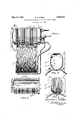
Myinvention relates to float housings for 1 showing the chilling coil fragmentarn V refrigerating plants, one function'of which and Fig. 4: is'anend elevational view thereof j is to intercept liquid refrigerant issuing from from 44 of Fig.1. i Y I i i the chilling coil of the refrigerating system f Sim'ilar characters of reference refer to; L and the objects of my invention are: First, similar parts and portions throughout the 55 to providea device of this class which'is an several views" of the drawingsi V eflicient conductor of heat from the sur- The valve housing 1 is. provided" with rounding airtothe refrigerantfs econd, to semi-cylindrical upper and lower portions provide a device which is provided with fin connectedby-straight sides and is open atits 10 means for increasing the contact area of the one'end. Integral'with the open endofthe e0 ,valvehousingwiththesurrounding air; third, float valve housing 1 isa circular collar memr to provide a device of this class which may be her 2. Said collar member forms flanges mounted adjacent to a conventional chilling which extend inwardly from the upper and coil and cooperate therewith; forth,,to' prolowerg portions of the valve housing and l V. vide a device of this class which absorbs heat other flanges which extend outwardlyyf-romf 5 7 from the surrounding air for gasifying the the side portions thereof, as shown best in Fig. surplus liquid refrigerant from the chilling 3 of the drawings. Secured to the collar coil; fifth, to provide a device of this class 2 is a plate A which supports-theexpansion which reduces to a minimum the quantity'of valve control means therefore and the inlets 2o refrigerant returning to the compressor in a and the ou'tletsfto the float chamber. The liquid state; sixth, to provide a device of this plateAa'nd the mechanism 'supportedthereon class which enables the refrigerant to absorb fo'rmno part of the present invention. Exthe maximum amount ofheatbeforereturning tending outwardly'from the sides of' the to the compressor; seventh, to provide a de housing 1 are aplurality ofispaced apart verg vice of this class which may be used with any tically positioned fins 3. Other vertical fins 7. conventional refrigeratingsystem and cool- 4 extend across the closed end-of the valve" ing unit; eighth, to provide a'device of this housing. It is preferred to construct the class which increases the efliciency of a recollar member, side and end flnsintegr'al,
frigerating system chilling unit, and ninth, with the float'housing. V j so to provide a device of this class which is The'housing 1 forms a receptacle forreto 1 simple of construction, durablefelflcient in ceiving refrigerant after passingxthrough its action, and which will not readily detethe chilling coil. Such refrigerant remain-I I riorate or get out of order. a a ing in liquid form is allowed to collectin the 5 With these and other objects in view as housing 1, thereby preventing its'pass'age to 3-3 will appear hereinafter, my invention contl e compressor until vaporized. 8 sists of certain novel features. of construc- Ordinarily thejfloat housing is positioned" tion, combination and arrangement of parts by means'of brackets or other suitable means i and portions as will be hereinafter described above the chilling coil C'of the refrigerating V in detail and particularly set forth in the apsystem, as shown in Fig. 1 of the drawings,
pended claims, reference being had to the ac- When mounted adjacent tothe chilling coil G companying drawings and to the characters the fins 3 of the float valve housing are shaped of reference thereon which form a partof so as'to provide ready means of mounting, 1 this application, in which: 1' p as shown in Figs. 3 and 4. In some refrig- Figure 1 is a side elevational view of my crating systems the chilling coil is placed float housing shown in connection with aabove the floathousing. In those cases the chilling unit of a refrigerating system; Fig. 2 float housing is simply hung. from the coils Y is a top or plan view of the float housing with or rested upon a surface and the coils mountparts and portions broken away and in seced upon the-float housing- Thus, whenthe tion to facilitate the illustration; Fig. 3 is float housing is placed adjacent to the chilling 50 a sectional view thereof through 33 of Fig. coils, it provides an effective additional chill- 109 V ing means. While the housing 1 is referred to as a float valve housing within which the conventional valve regulating float is adapted to function, it will be understood that the present invention relates broadly to a receptacle for liquid refrigerant and means for enhancing the evaporation of the liquid prior to its passage to the compressingmedium of a refrigerating system; Y 13 It is obvious that in the construction as il- I lustrated in the drawings and described in the foregoing specification that there is provided a float housingas aimed at and'set forth in the objects of the invention, and;
15 though I have shown and described a particular eonstruotiom, combination and arrangement of parts. and portions, I do not wish to be limited to this particular construetion, combination and arrangement butdesire to includ'e'in the scope of my invention the construction, combination and arrange ment substantially as set forth in the ap pendedfclaims, V r v Having thus described my invention, What I claim as new and desire to secure by Letters Patent is f '1.VIn arefrigeratingplant, a float valve housing forthe heat absorbing side of the v plant substantially oval-shape incross section, positioned with the maximum diameter vertical, and closed at both its top and bottorn sides. i v V 2. In a refrigerating plant, a float valve housing for the heat absorbing side of the plant substantially oval-shape in cross section, positioned with the maximum diameterv vertical, closed at both: its top and bottom' sides, and provided with integral'heat absorbing fins'extending on both its sides and is closed end thereof. V
"In testimony whereof, I have hereunto set o my hand at San Diego, California thisl4th day of October 1927. r
7 ROBERT L. MYERS.
Priority Applications (1)
| Application Number | Priority Date | Filing Date | Title |
|---|---|---|---|
| US227676A US1859932A (en) | 1927-10-21 | 1927-10-21 | Float valve housing for refrigerating plants |
Applications Claiming Priority (1)
| Application Number | Priority Date | Filing Date | Title |
|---|---|---|---|
| US227676A US1859932A (en) | 1927-10-21 | 1927-10-21 | Float valve housing for refrigerating plants |
Publications (1)
| Publication Number | Publication Date |
|---|---|
| US1859932A true US1859932A (en) | 1932-05-24 |
Family
ID=22854033
Family Applications (1)
| Application Number | Title | Priority Date | Filing Date |
|---|---|---|---|
| US227676A Expired - Lifetime US1859932A (en) | 1927-10-21 | 1927-10-21 | Float valve housing for refrigerating plants |
Country Status (1)
| Country | Link |
|---|---|
| US (1) | US1859932A (en) |
-
1927
- 1927-10-21 US US227676A patent/US1859932A/en not_active Expired - Lifetime
Similar Documents
| Publication | Publication Date | Title |
|---|---|---|
| US3332476A (en) | Carburetor cooling means | |
| US1552076A (en) | Drinking fountain | |
| US1859932A (en) | Float valve housing for refrigerating plants | |
| DE112019006726T5 (en) | COOLING DEVICE | |
| DE646207C (en) | Beverage cooler | |
| US2505934A (en) | Capillary refrigerant control, including dehydrator | |
| DE891425C (en) | Device for the operation of dry rectifiers | |
| US1821754A (en) | Air cooled condenser for refrigerating systems | |
| DE898917C (en) | Brine cooler closed on all sides | |
| US1881770A (en) | Oil cooling means | |
| DE1188627B (en) | Bottle cooler operated with Peltier elements | |
| US1303107A (en) | Oderman | |
| DE1129513B (en) | Hermetically sealed small refrigeration machine | |
| US2576877A (en) | Thermostatic valve controlling device | |
| DE599749C (en) | Cooling device preferably equipped with a compression refrigeration machine | |
| US2677242A (en) | Secondary refrigeration control system | |
| US1669141A (en) | Refrigerating machine | |
| US1900526A (en) | Control mechanism for evaporators | |
| DE539272C (en) | Evaporator for refrigeration systems | |
| US1813667A (en) | Apparatus for cooling internal combustion engines | |
| DE499329C (en) | Chiller | |
| USD104185S (en) | Design foe a portable lamp | |
| US1721654A (en) | Condenser and liquid receiver | |
| DE515311C (en) | Unidirectional heat transfer device | |
| US1467281A (en) | Manifold heater |