US1859931A - Leer - Google Patents
Leer Download PDFInfo
- Publication number
- US1859931A US1859931A US477034A US47703430A US1859931A US 1859931 A US1859931 A US 1859931A US 477034 A US477034 A US 477034A US 47703430 A US47703430 A US 47703430A US 1859931 A US1859931 A US 1859931A
- Authority
- US
- United States
- Prior art keywords
- tunnel
- hue
- leer
- temperature
- ware
- Prior art date
- Legal status (The legal status is an assumption and is not a legal conclusion. Google has not performed a legal analysis and makes no representation as to the accuracy of the status listed.)
- Expired - Lifetime
Links
- 238000001816 cooling Methods 0.000 description 25
- 239000007789 gas Substances 0.000 description 17
- 230000001276 controlling effect Effects 0.000 description 12
- 238000010438 heat treatment Methods 0.000 description 12
- 206010022000 influenza Diseases 0.000 description 9
- 239000000463 material Substances 0.000 description 5
- 238000000137 annealing Methods 0.000 description 4
- 238000002485 combustion reaction Methods 0.000 description 3
- 238000005034 decoration Methods 0.000 description 3
- 230000003247 decreasing effect Effects 0.000 description 3
- 238000007865 diluting Methods 0.000 description 3
- 230000004927 fusion Effects 0.000 description 3
- 230000033001 locomotion Effects 0.000 description 3
- 230000001105 regulatory effect Effects 0.000 description 3
- 208000006379 syphilis Diseases 0.000 description 3
- 230000000694 effects Effects 0.000 description 2
- 238000009413 insulation Methods 0.000 description 2
- 241001024099 Olla Species 0.000 description 1
- 230000003190 augmentative effect Effects 0.000 description 1
- 239000012809 cooling fluid Substances 0.000 description 1
- 239000004744 fabric Substances 0.000 description 1
- 230000004907 flux Effects 0.000 description 1
- 239000000446 fuel Substances 0.000 description 1
- 239000011521 glass Substances 0.000 description 1
- 238000004519 manufacturing process Methods 0.000 description 1
- 238000000034 method Methods 0.000 description 1
- 238000005192 partition Methods 0.000 description 1
- 230000000750 progressive effect Effects 0.000 description 1
- 230000000630 rising effect Effects 0.000 description 1
Images
Classifications
-
- C—CHEMISTRY; METALLURGY
- C03—GLASS; MINERAL OR SLAG WOOL
- C03B—MANUFACTURE, SHAPING, OR SUPPLEMENTARY PROCESSES
- C03B25/00—Annealing glass products
- C03B25/04—Annealing glass products in a continuous way
- C03B25/06—Annealing glass products in a continuous way with horizontal displacement of the glass products
Definitions
- This invention relates to leers for annealing glassware and more particularly to a spe cfic arrangement in a particular type of leer and incorporated with the temperature controlling means thereof, specifically the a-rrangement by which the fiow'of air or other temperature controlling media in the temperature controlling flues of theleer are regulated.
- the invention is a division of my copending application Serial N o. 242,- 877, filed December 27. 1927, now Patent N o. 1,798,552, issued March 31, 1931.
- Leers of the type to which this invention pertains may be in the form of long tunnel-- like ovens through which the glass may be passed slowly but continuously upon a suitable carrier, as for example, a belt of wire mesh fabric, suitable means being used to drive the belt.
- a suitable carrier as for example, a belt of wire mesh fabric, suitable means being used to drive the belt.
- the temperature inside the tunnel is controlled accurately to provide for the desired temperature gradient in the tunnel and in the ware by the provision o f one or more longitudinally extending temperature controllingv lues.
- portions of the cooling'air havebeen drawn ofi' at intervals, so that the remaining air in t-he iiues will have a decreasing cooling effect, which mayy be useful in connectlon with the Hue. carry ⁇ ing cooling air in a direction opposite to that of the movement of the ware.
- the objects of the present invention are to provide in connection with a leer of the above described character a substantially constant rate of cooling of the ware by controlling the iow through the several passages communicating with the tempera.
- this object may be achieved eitherV by'the provision of passages atl progressively decreasing distance apart lon tudinally of the leer communicating with t temperature controlling flues, or by roviding the passages with progressively lncreasing effective cross sectional areas toward the one end (usually the exit end) of the leer, or by a combination of these two methods.
- Figure 1 is a diagrammatic' vertical longitudinal sectional view of the forward half of a leer embodying my invention
- Fig. 2 is a similar View of the rear half of the leer shown in Fig. 1;
- Fig. 3 is a section taken substantiallyon the l1ne33 in Fig. 1;v
- Fig. 4 is a section taken substantially on the broken line 4-4 in Fig. 1; v
- Fig. 5 is a section taken substantially on the broken line 5 -5 in Fig Fig. 6 is a section taken substantially on the line 6 6 in Fig.'2;
- Fig. 7 is an elevation of one of the damper members for admitting amospheric air to the lower iiues having relatively small openings for air admission;
- Fig. 8 is an elevation of a damper member having larger openings
- Fig. 9 is a section on the line 9-'9 of Fi 7 and 8 showing the' conguiation of t e damper members.
- the leer tunnel l may be constructed of a plurality of substantially interchangeable sections 2 arranged in end to end relation and suitably Supported in any desired manner, as for example. the manner shown in my prior Patent 1,560,481, granted Nov. 3, 1925.
- the Ware may be carried through. the leer in any suitable manner, as for example, upon a flexible wire belt 3 which may be driven by suitable mechanism (not shown), this mechanism preferably being of the type shown in my prior patent above referred to.
- Heating ues 4 and 5 extend longitudinally beneath the forward and rear portions of the tunnel respectively and communicate through a passageway 6 with a common fire b0x7 disposed beneath the leer at a point spaced from the entrance end of the tunnel.
- the damper 8 controls the passage of the heating media through the flue 4 from the fire boxL 7, and thea damper 9 the passage of the heating media through flue 5, thus providing for independent regulation of the drafts in these flues.
- the fire box 7 may be provided with one or more suitable burners 10 for' oil, gas or other fuel which may be directed thereinto through the opening 11, air to support combustion entering the fire box through the annular space between the burner 10 and the sides of the opening 11. A desired amount of diluting air may beadmitted to the fire box 7 through the passage 12, this amount being controlled by a'suitable damper 13.
- suitable regulation of the burner 10 and the dampers 13, 8 and 9 the temperature and volume of the heating gases passing along the ues 4 and 5 respectively, may be controlled.
- the ue 4 is provided with an outlet passage 15 adjacent to the receiving end of the tunnel, which passage communicates with passages 16, one on each side of the tunnel, leading to header 17, which in turn communicates through the ducts 18 and 19 with the suction device 20, here shown as a motor driven fan.
- I provide a plurality of dampered air inlet passages 21 which are spaced apart unequal distances, as seen in Fig. 2, the distances being progressively less toward the discharge end of the leer.
- the effective area of these passages 21 may be progressively greater toward the discharge end of the leer, whereby with a' given damper setting,
- creasing amounts of cooling air will be a imitted per unit length of the tunnel.
- damper members with progressively greater openings, but all cooperable with ports of the same size.
- Such bars are shown in Figs. 7, 8 and 9 at 21a and 21b respectively and are provided with cut out segments 21 of varying length so that the bar 21a may, for example, be provided with four cut out portions or segments each of two inches length thus providing an aggregate length of eight inches,
- the bar 21b may be provided with two cut out segments each of fifteen inches, or an aggregate length of thirty inches.
- I plan to-use bars having progressively increasing total or aggregate cut out lengths or openings' toward the exit end of the leer for ac complishing the vaforesaid objects. The reason for this is that it requires less cooling air to cool the gases a given number of degrees at a point where they are hotter and their total volume is less than where they are cooler, and the size and disposition of these inlets is such at with the dampers set at a certain angle, the temperature drop per unit length of tunnel will be constant, so that the rate of cooling of the ware in the tunnel will be substantially constant. ⁇ This is an important feature, as leers of this character are usually operated by relatively unskilled labor, and in order to have proper operation with dampers and passages of uniform size and spacing, different damper settings would be required which would require the services of a skilled operator.
- the flue 5 communicates through an inclined passage 22 with a header 23, communicating in turn with passages 24, one-on each side of the tunnel 1, which lead to a top header or wind box 25 communicating with the fan 20.
- iiues 4 and 5 are at all times maintained at subatmospheric pressure, whereby any leaks in these flues, as for example, in the joints between contiguous sections 2, will not permit the combustion products -to impinge upon the ware or cause hot spots inthe tunnel, but will only serve to withdraw slight amounts of air from the tunnel which has no harmful effect. .v
- the portion 26 formed as a prolongation of the iue 5 to the right of the inclined passage 22 (as seen in Fig. 2) is used toaccelcrate the cooling of the -ware and is provided with a dampered air inlet passage 27 adjacent to the discharge end of the leer, cold air from the atmosphere flowing through the passage 27 and to the passage 22 countercurrent to the direction of motion of the ware.
- Flues 2 8 and 29 extend longitudinally above the tunnel l and preferably have acommon Wall with a roof of said tunnel in the same manner that flues 4 and 5 have a common wall with the floor of the tunnel.
- a specially de signed fire box 30 is interposed between the filles 28 and 29 and has a common wall 31 with the top of the tunnel.
- Fire box 30 is provided with a plurality of burners 31 syn1- metrically disposed with respect thereto, preferably three on each side, these burners being directed into openings 32, similar te the opening 11 in fire box 7 and having annular spaces as described above to provide for the entrance of primary air to support combustion.
- Openings 33 controlled by dampers 34 are provided, preferably one for each of the burners 31 for the purpose of admitting controllable amounts of secondary and diluting air, the control beingsimilar to that described above in connection with the lower fire box 7.
- the flue 28 is provided with one or more outlet openings 35, two being shown, which are controlled by suitable dampers 36 and which communicate through header 17 and conduits 18 and 19 with the fan 20.
- Flue 29 may be provided with a. plurallty of dampered air inlet openings 37, two of which are. shown, for the same purpose dcscribed above in connection with air inlet openings 21.
- This flue is separated by a suitable dividing wall 38 from a cooling flue 39, to be described.
- the heating media are drawn off from the l'lue 29 by one or more suitable passages 40 controlled by dampers 41, the passages 40 communicating through the conduit 19 with the suction fan 20.
- dampers 41 the draft through flues 28 and 29 is controlled respectively by dampers. 3G and 41 in a manner similar to that in which the draft throughlues 4 and 5 is controlled by dampers 8 and 9 respectively.
- the Hue 39 is formed as a prolongation of the l'lue 29 at the cooler end portion of the leer for accelerating the cooling of the ware, and is open to the atmosphere at the exit end of the leer as shown at 42.
- the Hue 39 communicates with the conduit 19 through a plurality of spaced dampere'd air outlet passages 43 by which the amount of cooling air drawn in a direction counter-current to that of the movement of theV ware through the flue 29, and the distance which it passes may be controlled.
- the glassware entering the left hand end is at substantially room temperature and is heated at a safe rate by transmitted and radiated heat, and to a lesser extent by convection currents, from the llues 4 and 28 in which the gases flow in a direction countercurrent to the Ware, so that by the time the Ware reachesa point substantially above the passageway 6, it has been brought almost to the fusing temperature of the decorating material or the flux used therewith.
- the ware will be maintained at a substantially constant temperature,- due Vto the fact that the gases in the lues 5 and 28 are traveling in opposite directions, and thus each tends to balance the temperature drop Vin the other.
- the ware In the next zone, that is, immediately under the furnace 30, which is of substantial longitudinal extent and which is of substantially Vthe same width as the tunnel, the ware will be maintained again at a substantially con- Stant temperature which may be maintained slightly higher than the temperature in the. preceding rane. During the passage through these two zones, the fusion of the decorating material onto the ware takes place. It is necessary to provide a material time for this fusion to take place as well as a certain temperature, so that the offset position of fire boxes7 and 30 and the longitudinal extent of fire box 30 are both of prime importance.
- the heating eii'ect on the ware by fire box 30 is still further augmented by the fact that this fire box has a common wall with the roof of the tunnel for substantially its entire length and breadth, and the burners 31 therein are symmetrically disposed with respect to the fire box, so that a contant temperature may be maintained.
- the normal rate of cooling of the ware is retarded to permit the permanent strains to work themselves out of the ware and to permit it to be cooled to a point below which they will not be reintroduced.
- the cooling below this temperature may be carried on at a relatively rapid' rate.
- the annealing and cooling portions of the leer to the right, as seen in Figs. 1 and 2 of the fire box 30, are preferably regulated so that all portions of the leer in any t1 ansversesection will be maintained at a substantially constant temperature, thus tending to remove any strainswhich have been previously introduced by differential heating-or in any other manner.
- Accelerated cooling takes place in the succeeding zones, too rapid cooling being prevented in the first part of these zones by carrying the lower Hue 5 to a point nearer the discharge end of the leer than the upper heating Hue 29 and depending upon hot convection currents rising from the hot lower Hue and cool currents moving 4downward from the cooler upper Hue 39 to govern the rate of cooling of the ware.
- the final cooling immediately adjacent to the discharge end of the tunnel may be further accelerated by providing the Acounter-current cold air Hue 26 in addition to the cooling effect of the top Hues 39.
- the leer tunnel used for decorating purposes may well be longer than in the ordinary -annealingdeen such as is shown in my prior patent above referred to, so as to provide the necessary space and time for heatin the ware from room temperature to the usion temperature of the decorating material and for maintaining it at the high fusion temperature before the annealing is started.
- a -leer comprising an elongate tunnel, means for moving articles of glassware therethrough, a longitudinally extending temperature controlling Hue associated with said tunnel and communicating at one end with a.
- a leer comprising an elongate tunnel, means for moving articles of glassware therethrough, a longitudinal heating Hue associated with said tunnel, means for supplying hot gases thereto, a plurality of dampered air inlet openings disposed at intervals along said Hue, and means for withdrawing the gases from the cooler end of said Hue, the disposition of ⁇ the air, inlet openings being such that increasingA amounts of air will be admitted toward the cooler end of said Hue per unit of length, whereby the temperature drop in the Hue may be maintained constant per unit of length with the same damper settings at each of saidair inlet openings.
- a leer comprising an elongate tunnel, means for moving articles of glassware therethrough, a longitudinally extending temperature controlling Hue associated with said tunnel and communicating at one end with I passages 4.
- leer comprising an elongate tunnel,
- ymeans for moving articles of glassware therethrou h a longitudinal heating Hue associated vith said tunnel, means for supplying hot gases thereto, a pluralityof dampered air inlet openings disposed at intervals along said Hue, and means for withdrawing the -gases from the Acooler end' of said Hue, the
- a leer comprising an elongate tunnel
- dampered passages communi-l means for moving articles of glassware there. through, a longitudinally extending temperature controlling Hue associated with said ltunnel and communicating at one end with a source of temperature controlling media, a plurality of dampered passages communicating with said Hue at intervals along its length, the said passages being progressively closer together from ⁇ one end of said Hue to the other and having progressively increasing cross sectional areas, and means for causing a How of temperature controlling media through said Hue and said passages, whereby the temperature gradient of the'ware controlled by said Hue may be maintained substantially constant the unit of length of the leer by the same damper settings at each of said passages.
- a leer comprising an elongate tunnel, means for moving articles of glassware therethrough, a longitudinal heating Hue associated with said tunnel, means for supplying hot gases thereto, a plurality of dampered air inlet openings disposed at intervals along said Hue, and means for withdrawing the gases from the cooler end of said Hue, the disposition and sizes of said air inlet openings being such that increasing amounts of air will be admitted toward the cooler end of said Hue per unit of length, whereby the temperature drop in the Hue may be maintained constant per unit of length with the same damper settings at each of said air inlet open- 1n s. Lligned at Hartford, Connecticut, this 19th 4 day of August, 1930.
Landscapes
- Chemical & Material Sciences (AREA)
- Engineering & Computer Science (AREA)
- Materials Engineering (AREA)
- Organic Chemistry (AREA)
- Drying Of Solid Materials (AREA)
Description
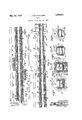
May 24, 1932. v. MULHOLLAND LEER Original Filed Dec. 27. 1927 [nz/enfof Ver YMU//z olla/7d 8% E .gmk
WN N
. jm M QN m N h.. Q
` .WNNMFFIWILLVL Ill e @n AN W Patented May 24, 1932 UNITED STATES PATENT OFFICE VERO-IL MULHOLLAND, OF WEST HARTFORD, CONNECTICUT, ASSIGNORTO HARTFORD- EMPIRE COMPANY, OF HARTFORD, CONNECTICUT, A CORPORATION OF DELAWARE LEER Original application iled December 27, 1927, Serial No. 242,877. Divided and this applicatie; mea August 22, 1930. Serial No. 477,034.
This invention relates to leers for annealing glassware and more particularly to a spe cfic arrangement in a particular type of leer and incorporated with the temperature controlling means thereof, specifically the a-rrangement by which the fiow'of air or other temperature controlling media in the temperature controlling flues of theleer are regulated. As such, the invention is a division of my copending application Serial N o. 242,- 877, filed December 27. 1927, now Patent N o. 1,798,552, issued March 31, 1931.
Leers of the type to which this invention pertains may be in the form of long tunnel-- like ovens through which the glass may be passed slowly but continuously upon a suitable carrier, as for example, a belt of wire mesh fabric, suitable means being used to drive the belt.
The temperature inside the tunnel is controlled accurately to provide for the desired temperature gradient in the tunnel and in the ware by the provision o f one or more longitudinally extending temperature controllingv lues.
In the present instance I have shown flues both above and below the tunnel through which the glassware is passed, butit willbe understood that either of theseiiue systems may be used alone or a flue system may be used solely for carryin a cooling fluid, such as cooling air drawn rom the atmosphere. In the past there have been provided in connection with leers of the above described character, passages communicating with the temperature controllingl iiues at intervals longitudinally lof their length by which' air may be drawn in for the-purpose of diluting and cooling the heated gases within the lines, or gases from the lues may be withdrawn at intervals for the purpose of increasing the temperature drop on the downstream side of the withdrawal points, in the case of heated gases. f
In a similar manner in connection with fiues used solely for cooling, portions of the cooling'air havebeen drawn ofi' at intervals, so that the remaining air in t-he iiues will have a decreasing cooling effect, which mayy be useful in connectlon with the Hue. carry` ing cooling air in a direction opposite to that of the movement of the ware.
Among .the objects of the present invention are to provide in connection with a leer of the above described character a substantially constant rate of cooling of the ware by controlling the iow through the several passages communicating with the tempera.
ture controlling iues in such a manner that substantially the same damper settings at each of the passages will give the desired results, thus roviding for operation and conrgl of the eer by comparatively unskilled a or.
In practice, this object may be achieved eitherV by'the provision of passages atl progressively decreasing distance apart lon tudinally of the leer communicating with t temperature controlling flues, or by roviding the passages with progressively lncreasing effective cross sectional areas toward the one end (usually the exit end) of the leer, or by a combination of these two methods.
Other objects and advantages of my in vention will appear from ythe following specification and sub-joined claims when taken in connection drawings, in which: v
Figure 1 is a diagrammatic' vertical longitudinal sectional view of the forward half of a leer embodying my invention;
Fig. 2 is a similar View of the rear half of the leer shown in Fig. 1;
Fig. 3 is a section taken substantiallyon the l1ne33 in Fig. 1;v
Fig. 4 is a section taken substantially on the broken line 4-4 in Fig. 1; v
Fig. 5 is a section taken substantially on the broken line 5 -5 in Fig Fig. 6 is a section taken substantially on the line 6 6 in Fig.'2;
Fig. 7 is an elevation of one of the damper members for admitting amospheric air to the lower iiues having relatively small openings for air admission; f
Fig. 8 is an elevation of a damper member having larger openings; and
Fig. 9 is a section on the line 9-'9 of Fi 7 and 8 showing the' conguiation of t e damper members.
with the accompanying Referring to the drawings', the leer tunnel l may be constructed of a plurality of substantially interchangeable sections 2 arranged in end to end relation and suitably Supported in any desired manner, as for example. the manner shown in my prior Patent 1,560,481, granted Nov. 3, 1925. The Ware may be carried through. the leer in any suitable manner, as for example, upon a flexible wire belt 3 which may be driven by suitable mechanism (not shown), this mechanism preferably being of the type shown in my prior patent above referred to. Heating ues 4 and 5 extend longitudinally beneath the forward and rear portions of the tunnel respectively and communicate through a passageway 6 with a common fire b0x7 disposed beneath the leer at a point spaced from the entrance end of the tunnel. The damper 8 controls the passage of the heating media through the flue 4 from the fire boxL 7, and thea damper 9 the passage of the heating media through flue 5, thus providing for independent regulation of the drafts in these flues. The fire box 7 may be provided with one or more suitable burners 10 for' oil, gas or other fuel which may be directed thereinto through the opening 11, air to support combustion entering the fire box through the annular space between the burner 10 and the sides of the opening 11. A desired amount of diluting air may beadmitted to the fire box 7 through the passage 12, this amount being controlled by a'suitable damper 13. By suitable regulation of the burner 10 and the dampers 13, 8 and 9, the temperature and volume of the heating gases passing along the ues 4 and 5 respectively, may be controlled. It is usually desirable to control the temperature of the gasespassing from the fire box into filles through the passage 6 within narrow limits, and by suitable control of the amounts and velocity of gases passing along the ues 4 and 5, the temperature drop along these flues may be varied at will, as the heat loss through the insulation 14 from the flue 4, and the forward portion of the flue 5, will not vary materially with a change in the velocity of the gases passing therethrough. The ue 4 is provided with an outlet passage 15 adjacent to the receiving end of the tunnel, which passage communicates with passages 16, one on each side of the tunnel, leading to header 17, which in turn communicates through the ducts 18 and 19 with the suction device 20, here shown as a motor driven fan. v
In order to control the temperature gradient in the tunnel 1 by cooling the gases in the Hue 5, I provide a plurality of dampered air inlet passages 21 which are spaced apart unequal distances, as seen in Fig. 2, the distances being progressively less toward the discharge end of the leer. Instead of this progressive change in the spacing of the passages, or in addition thereto, the effective area of these passages 21 may be progressively greater toward the discharge end of the leer, whereby with a' given damper setting,
that is, with the dampers in all of the passages 21 opened at a certain given angle, in-
creasing amounts of cooling air will be a imitted per unit length of the tunnel. In
practice a convenientway of accomplishing this variation using similarv parts for economy in manufacture is to provide damper members with progressively greater openings, but all cooperable with ports of the same size. I prefer to construct the dampers from cylindrical bars and having cut out segmentsto permit the passage of air when the bars are rotated to the proper positions. Such bars are shown in Figs. 7, 8 and 9 at 21a and 21b respectively and are provided with cut out segments 21 of varying length so that the bar 21a may, for example, be provided with four cut out portions or segments each of two inches length thus providing an aggregate length of eight inches,
while the bar 21b may be provided with two cut out segments each of fifteen inches, or an aggregate length of thirty inches. I plan to-use bars having progressively increasing total or aggregate cut out lengths or openings' toward the exit end of the leer for ac complishing the vaforesaid objects. The reason for this is that it requires less cooling air to cool the gases a given number of degrees at a point where they are hotter and their total volume is less than where they are cooler, and the size and disposition of these inlets is such at with the dampers set at a certain angle, the temperature drop per unit length of tunnel will be constant, so that the rate of cooling of the ware in the tunnel will be substantially constant. `This is an important feature, as leers of this character are usually operated by relatively unskilled labor, and in order to have proper operation with dampers and passages of uniform size and spacing, different damper settings would be required which would require the services of a skilled operator.
.The flue 5 communicates through an inclined passage 22 with a header 23, communicating in turn with passages 24, one-on each side of the tunnel 1, which lead to a top header or wind box 25 communicating with the fan 20. Thus it will be seen that iiues 4 and 5 are at all times maintained at subatmospheric pressure, whereby any leaks in these flues, as for example, in the joints between contiguous sections 2, will not permit the combustion products -to impinge upon the ware or cause hot spots inthe tunnel, but will only serve to withdraw slight amounts of air from the tunnel which has no harmful efect. .v
The portion 26 formed as a prolongation of the iue 5 to the right of the inclined passage 22 (as seen in Fig. 2) is used toaccelcrate the cooling of the -ware and is provided with a dampered air inlet passage 27 adjacent to the discharge end of the leer, cold air from the atmosphere flowing through the passage 27 and to the passage 22 countercurrent to the direction of motion of the ware.
Flues 2 8 and 29 extend longitudinally above the tunnel l and preferably have acommon Wall with a roof of said tunnel in the same manner that flues 4 and 5 have a common wall with the floor of the tunnel. A specially de signed fire box 30 is interposed between the filles 28 and 29 and has a common wall 31 with the top of the tunnel. Fire box 30 is provided with a plurality of burners 31 syn1- metrically disposed with respect thereto, preferably three on each side, these burners being directed into openings 32, similar te the opening 11 in fire box 7 and having annular spaces as described above to provide for the entrance of primary air to support combustion. Openings 33 controlled by dampers 34 are provided, preferably one for each of the burners 31 for the purpose of admitting controllable amounts of secondary and diluting air, the control beingsimilar to that described above in connection with the lower fire box 7.
The flue 28 is provided with one or more outlet openings 35, two being shown, which are controlled by suitable dampers 36 and which communicate through header 17 and conduits 18 and 19 with the fan 20.
When used as a decorating leer, the glassware entering the left hand end, as seen in Fig. 1, is at substantially room temperature and is heated at a safe rate by transmitted and radiated heat, and to a lesser extent by convection currents, from the llues 4 and 28 in which the gases flow in a direction countercurrent to the Ware, so that by the time the Ware reachesa point substantially above the passageway 6, it has been brought almost to the fusing temperature of the decorating material or the flux used therewith. In thenext zone to the front edge of the lire box 30, the ware will be maintained at a substantially constant temperature,- due Vto the fact that the gases in the lues 5 and 28 are traveling in opposite directions, and thus each tends to balance the temperature drop Vin the other. In the next zone, that is, immediately under the furnace 30, which is of substantial longitudinal extent and which is of substantially Vthe same width as the tunnel, the ware will be maintained again at a substantially con- Stant temperature which may be maintained slightly higher than the temperature in the. preceding rane. During the passage through these two zones, the fusion of the decorating material onto the ware takes place. It is necessary to provide a material time for this fusion to take place as well as a certain temperature, so that the offset position of fire boxes7 and 30 and the longitudinal extent of fire box 30 are both of prime importance. The heating eii'ect on the ware by fire box 30 is still further augmented by the fact that this fire box has a common wall with the roof of the tunnel for substantially its entire length and breadth, and the burners 31 therein are symmetrically disposed with respect to the fire box, so that a contant temperature may be maintained.
In fusing the decoration on certain types of ware, namely that type in which the decoration is all adjacent to the top of the articles and in which the articles are relatively light it is sometimes desirable to heat the top decorated portion hotter than the bottom, so as to mature the decoration without the possibility of heating thebottom portion to an extent likely to cause, deformation thereof. The particular type of fire box 30 and its individual control, apart from-that ,of the fire box 7, is especially adapted for this purpose.
After the color has been matured on the Ware, either with or Without differential heating as described above, it must be annealed to take out any strains which may have been introduced and to prevent the introduction of new strains. and for this purpose a material length or zonein the tunnel is provided, namely that shown in Fig. 1 to the right of the lire box 30. in which zone" there are no passages to the fines 5 and 29 for the entrance of cooling air, but the temperature is regulated by thevelocity control described above and by the decreasing thickness ofthe insulation 14. The succeeding zone of the tunnel which may be said to be that portion shown at the left in Fig. 2 to a point near the partition 38 between the Hues 29 and 39, vconstitutes a retarded cooling zone in -which the ware is slowly'cooled Ato approximately the lower annealing temperature? or the temperature below which permanent strains cannotbe reintroduced into the ware ,even though it is cooled very rapidly. During its passage from a position under the tire box 30 to approximately the end of this last mentioned zone, the normal rate of cooling of the ware is retarded to permit the permanent strains to work themselves out of the ware and to permit it to be cooled to a point below which they will not be reintroduced.
The cooling below this temperature may be carried on at a relatively rapid' rate. The annealing and cooling portions of the leer to the right, as seen in Figs. 1 and 2 of the fire box 30, are preferably regulated so that all portions of the leer in any t1 ansversesection will be maintained at a substantially constant temperature, thus tending to remove any strainswhich have been previously introduced by differential heating-or in any other manner. Accelerated cooling takes place in the succeeding zones, too rapid cooling being prevented in the first part of these zones by carrying the lower Hue 5 to a point nearer the discharge end of the leer than the upper heating Hue 29 and depending upon hot convection currents rising from the hot lower Hue and cool currents moving 4downward from the cooler upper Hue 39 to govern the rate of cooling of the ware. The final cooling immediately adjacent to the discharge end of the tunnel may be further accelerated by providing the Acounter-current cold air Hue 26 in addition to the cooling effect of the top Hues 39.
The leer tunnel used for decorating purposes may well be longer than in the ordinary -annealingdeen such as is shown in my prior patent above referred to, so as to provide the necessary space and time for heatin the ware from room temperature to the usion temperature of the decorating material and for maintaining it at the high fusion temperature before the annealing is started.
It should be noted that the top Hues 28, 29
and 39 are all connected with the single suction device 20 and are maintained at subatmospheric pressure for the reasons described above in connection with the lower Hues 4 and 5.
While I have shown and described but one embodiment of my invention, it is to-be understood that many changes might be made therein, and described might be used in other connectionsand I do not wish, therefore, to be limited except by the scope`of the appended claims, which are to be construed as broadly as the prior art permits.
and many of the ldetails herein shown I claim as my invention:
1. A -leer comprising an elongate tunnel, means for moving articles of glassware therethrough, a longitudinally extending temperature controlling Hue associated with said tunnel and communicating at one end with a.
source of temperature controlling media, a plurality of dampered passages communicating with said Hue and disposed at intervals therealong, said passages being progressively closer together along the length of said Hue, whereby the temperature gradient in the ware controlled by said Hue may be maintained constant per unit of length of the leer' with the same damper settings at each of said passages. v
2.` A leer comprising an elongate tunnel, means for moving articles of glassware therethrough, a longitudinal heating Hue associated with said tunnel, means for supplying hot gases thereto, a plurality of dampered air inlet openings disposed at intervals along said Hue, and means for withdrawing the gases from the cooler end of said Hue, the disposition of `the air, inlet openings being such that increasingA amounts of air will be admitted toward the cooler end of said Hue per unit of length, whereby the temperature drop in the Hue may be maintained constant per unit of length with the same damper settings at each of saidair inlet openings.
3. A leer, comprising an elongate tunnel, means for moving articles of glassware therethrough, a longitudinally extending temperature controlling Hue associated with said tunnel and communicating at one end with I passages 4. leer comprising an elongate tunnel,
ymeans for moving articles of glassware therethrou h, a longitudinal heating Hue associated vith said tunnel, means for supplying hot gases thereto, a pluralityof dampered air inlet openings disposed at intervals along said Hue, and means for withdrawing the -gases from the Acooler end' of said Hue, the
sizes of said air inlet openings being progressively increased so that increasing amounts of air will be admitted toward the cooler end of said Hue per unit of length, whereby the temperature drop in the Hue may be maintained constant per unit of length with the same damper settings at each of said air inlet openings.
5. A leer comprising an elongate tunnel,
of dampered passages communi-l means for moving articles of glassware there. through, a longitudinally extending temperature controlling Hue associated with said ltunnel and communicating at one end with a source of temperature controlling media, a plurality of dampered passages communicating with said Hue at intervals along its length, the said passages being progressively closer together from` one end of said Hue to the other and having progressively increasing cross sectional areas, and means for causing a How of temperature controlling media through said Hue and said passages, whereby the temperature gradient of the'ware controlled by said Hue may be maintained substantially constant the unit of length of the leer by the same damper settings at each of said passages.
6. A leer comprising an elongate tunnel, means for moving articles of glassware therethrough, a longitudinal heating Hue associated with said tunnel, means for supplying hot gases thereto, a plurality of dampered air inlet openings disposed at intervals along said Hue, and means for withdrawing the gases from the cooler end of said Hue, the disposition and sizes of said air inlet openings being such that increasing amounts of air will be admitted toward the cooler end of said Hue per unit of length, whereby the temperature drop in the Hue may be maintained constant per unit of length with the same damper settings at each of said air inlet open- 1n s. Lligned at Hartford, Connecticut, this 19th 4 day of August, 1930.
VERGIL MULHOLLAND.
Priority Applications (1)
| Application Number | Priority Date | Filing Date | Title |
|---|---|---|---|
| US477034A US1859931A (en) | 1927-12-27 | 1930-08-22 | Leer |
Applications Claiming Priority (2)
| Application Number | Priority Date | Filing Date | Title |
|---|---|---|---|
| US242877A US1798552A (en) | 1927-12-27 | 1927-12-27 | Leer |
| US477034A US1859931A (en) | 1927-12-27 | 1930-08-22 | Leer |
Publications (1)
| Publication Number | Publication Date |
|---|---|
| US1859931A true US1859931A (en) | 1932-05-24 |
Family
ID=26935415
Family Applications (1)
| Application Number | Title | Priority Date | Filing Date |
|---|---|---|---|
| US477034A Expired - Lifetime US1859931A (en) | 1927-12-27 | 1930-08-22 | Leer |
Country Status (1)
| Country | Link |
|---|---|
| US (1) | US1859931A (en) |
-
1930
- 1930-08-22 US US477034A patent/US1859931A/en not_active Expired - Lifetime
Similar Documents
| Publication | Publication Date | Title |
|---|---|---|
| US3261596A (en) | Annealing and decorating lehrs | |
| US2458040A (en) | Lehr | |
| US1505768A (en) | Tunnel kiln and method of operating same | |
| US1859931A (en) | Leer | |
| US2232638A (en) | Lehr | |
| US1875365A (en) | begeman | |
| US1588603A (en) | Apparatus for annealing glassware | |
| US2151983A (en) | Method of and apparatus for decorating and annealing glassware | |
| US1798552A (en) | Leer | |
| US2335128A (en) | Lehr for glassware | |
| US2162377A (en) | Glass annealing lehr | |
| US1947408A (en) | Method of and apparatus for annealing glassware | |
| US1896874A (en) | Glassware annealing leer and drift controlling apparatus therefor | |
| US1742099A (en) | Drying oven | |
| US1882992A (en) | Method of heating glass and apparatus therefor | |
| US1846566A (en) | Annealing glassware | |
| US2133783A (en) | Method of and apparatus for annealing glassware | |
| US2991535A (en) | Tunnel kiln firing section | |
| US2089250A (en) | Glass annealing leer | |
| US1853878A (en) | Glass annealing leer | |
| US1595912A (en) | Method of annealing and cooling sheet glass | |
| US2784531A (en) | Lehr for ceramic enameled glass bulbs | |
| US1841060A (en) | Method and apparatus for controlling muffle leers | |
| US1982478A (en) | Method of and apparatus for annealing glassware | |
| US1389583A (en) | Decorating or annealing oven |