US1859927A - Electric heat control - Google Patents
Electric heat control Download PDFInfo
- Publication number
- US1859927A US1859927A US403255A US40325529A US1859927A US 1859927 A US1859927 A US 1859927A US 403255 A US403255 A US 403255A US 40325529 A US40325529 A US 40325529A US 1859927 A US1859927 A US 1859927A
- Authority
- US
- United States
- Prior art keywords
- casing
- thermostatic
- terminal
- arm
- adjustable
- Prior art date
- Legal status (The legal status is an assumption and is not a legal conclusion. Google has not performed a legal analysis and makes no representation as to the accuracy of the status listed.)
- Expired - Lifetime
Links
Images
Classifications
-
- H—ELECTRICITY
- H01—ELECTRIC ELEMENTS
- H01R—ELECTRICALLY-CONDUCTIVE CONNECTIONS; STRUCTURAL ASSOCIATIONS OF A PLURALITY OF MUTUALLY-INSULATED ELECTRICAL CONNECTING ELEMENTS; COUPLING DEVICES; CURRENT COLLECTORS
- H01R13/00—Details of coupling devices of the kinds covered by groups H01R12/70 or H01R24/00 - H01R33/00
- H01R13/66—Structural association with built-in electrical component
- H01R13/70—Structural association with built-in electrical component with built-in switch
- H01R13/713—Structural association with built-in electrical component with built-in switch the switch being a safety switch
- H01R13/7137—Structural association with built-in electrical component with built-in switch the switch being a safety switch with thermal interrupter
Definitions
- This invention relates to a thermostatic control of the heat supplied by an electric current.
- the invention as shown in the accompanymg drawings, may be applicable to many electrical heating appliances.
- the manually adjustable element is so arranged with respect to the electric conductor that these parts of the appliance will operate harmoniously without one of them interfering with the operation of the other.
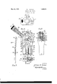
- Fig. 1 is an end view of the appliance looking at the end thereof with which the electric conductors are connected.
- i Fig. 2 is an inside plan view of the base and contained parts, with the cap removed.
- Fig. 3 is a view partly in section and partly in side elevation of the appliance on line 3-3 of Fig. 2.
- Fig. 4 is a partial cross section and partial end view on line 4-4 of Fig. 2.
- Fig. 5 is a side elevation of the thermostat member, a portion of said member being sectioned to show more clearly the bi-metallic construction thereof.
- the cord comprises the two conductors 16 and 17, said cord being protected by a cord holding spring 18.
- Said cord 17 is not connected axially with the casing 7, but is led into an opening 20 in said casing in a diagonal manner, and in such a way as to leave unobstructed the adjacent central end portion of the casing.
- the conductor 16 is secured to a terminal 23 provided with a binding post 24 which may be of well known construction.
- Said terminal 23 is in direct electrical contact with the cooperating spring clips 25 between which are telescoped the terminal posts (not shown) of the sad iron element.
- the terminal clips 27 which, by means of a binding post 28, are maintained 1n electric connection with a base plate 29.
- Said base plate 29, on the side thereof next to the center of the appliance, is provided with an upstanding flange 30 to which is riveted or otherwise secured a thermostatic member or arm 31.
- thermostatic member is illustrated by way of example, in a detailed manner in Fig. 5, being shown in said view as consisting of a brass strip 33 combined with a steel strip 34, and having at its free end a contact point 35 secured thereto.
- thermostatic member With said thermostatic member cooperates an adjustable terminal 37 having a bevelled contact face 38 which cooperates with the contact point 35 of the thermostatic member.
- Said terminal 37 is preferably formed as a slidable block having therethrough a screw threaded bore 39 into which is screwed the stem 40 of a control screw shaft which extends axially with respect to the casing 7 and projects from one end of said casing having fixed to its projecting end a manually rotatable knob 41.
- Said knob 41 is preferably milled and provided with an outwardly extending base flange 42 upon which is inscribed an indicating arrow 42a which cooperates with the arrows on the casing marked Hot Oif and Medium to indicate the degrees of heat supplied by the heating element. Additional marks 42?; and 420 may be supplied on flange 42 to indicate intermediate degrees of heat.
- the adjustable terminal 37 is formed as a block which fits slidably within an upwardly extending guide or flange portion 45 with which the base plate 46 is provided, said base plate 46 being held in place by the screws 47 and the conductor 17 being electrically connected with said base plate by means of the terminal screw 49.
- Said control or adjusting stem 40 has formed thereon or secured thereto a collar or radially projecting flange 50 which fits in between theguide flange 45 and the shoulder portion 51 of the casing through which said stem 40 extends.
- the base plate 46 is provided with an upstanding flange or ear 53 which supports the inner end ofsaid stem 40 and within which that end of the stem has a working fit. Collar 50, shoulder 51 and ear 53 provide means which prevent lengthwise movement of the stem 40 while permitting rotation thereof.
- thermostatic member 31 and adjustable terminal 37 are so arranged with relation to each other that, when said terminal 37 is properly adjusted, the proper amount of current is supplied to the sad iron, or other electrically heated implement, to maintain such implement at the desired degree of heat.
- thermostatic member When the heat falls below the desired amount the thermostatic member will automatically move its contact point 35 into contact with beveled face 38 of the adjustablev terminal 37, and as soon as the heat 'exceeds the predetermined amount said thermostatic member 31 will automatically withdraw its contact point 35 from the face 38 of the contact 37 thus breaking the circuit and allowing the electrically heated element to cool until the thermostatic member again automatically restores the electric connection.
- thermostatic arm 31 Normally the contact point 35 of the thermostatic arm 31 will be in engagement with the contact face 38 of the adjustable terminal 37, but when the appliance is connected with a source of electric current supply, heat will begin to be supplied by conduction to the thermostat member 31 and, when 'such heat exceeds the predetermined temperature for which the control stem 40 has been set, the contact point 35 of the thermostatic member will be moved away from the contact face 38.
- the thermostatic arm or member 31 is provided with a laterally deflected portion 31a for a considerable distance from its free end, thus to adapt it to cooperate properly with the terminal 37 when said terminal is advanced and retracted in a direction parallel to the body portion of the thermostatic arm 31.
- the upstanding flange or ear 53 which supports the inner end of stem 40 is adapted also to act as a stop to limit the movement of the thermostatic arm 31 toward the adjustable terminal 37.
- This arrangement makes it possible to retract said terminal 37 sufiiciently to completely out off theelectric current even while the appliance is connected with a source of electric current supply.
- the indicating marks shown in Fig. 1 are so arranged that when the movable terminal 37 is retracted to this extent the arrow 42a points to the Off position.
- the post 53 is provided with insulating material 53a against which the thermostatic arm rests at such time while the free end thereof is out of contact with the movable terminal 37
- This insulated stop means for the thermostatic arm makes it 'unnecessary to adjust with any great precision the position which said arm assumes when in the cold condition. It is desirable that the rotatable adjusting knob 41 be located at one end of the elongated casing upon which it is mounted so that said knob may readily be adjusted with one hand while the other hand grasps said casing.
- an adjustable appliance for thermostatically controlling the supply of electric current, an elongated casing of insulating material, a thermostatic control device within said casing adapted to be connected at one end of the casing with, an'appliance tobe electrically heated, a manually operable adjusting member for said thermostatic device projecting externally and axially from the other end of the casing, and a cord holding device extending diagonally with relation to the axis of the casing and connected therewith in spaced relation to said adjusting member.
- an adjustable appliance adapted for thermostatically controlling the supply of electric current to sad irons, acasing of insulating material, electrical connections in said casing, and a thermostatic arm of the bimetallic laterally deflectable type to control the supply of current through said connections, said thermostatic arm being anchored at one end and being bent to deflect a portion thereof at its free end, and a movable contact to cooperate with the free end portion of said arm, said movable contact being in approximate axial alinement with the anchored portion of said arm and being adjustable toward and from the anchorage of said arm. 4.
- an adjustable appliance adapted for thermostatically control ing the supply of electric current to sad irons, an elongated casing of insulated material, electrical connections in said casing, a thermostatic arm which extends lengthwise of said casing and whichis of the laterally deflectable bi-metallie type to control the supply of current through said connections, sald thermostatic arm having a contact mounted upon one side of its free end portion, an adjustable contact which is adapted to cooperate with the contact carried by said arm, and manually operable means to adjust said movable contact lengthwise of the casing, said adjustable'contact having a contact-making face which is inclined with respect to the length of the casing.
- a thermostat proper consisting of an arm which at times forms part of the electric circuit and which is positioned at all times to have its temperature affected by heat from an element which is heated by said electric circuit, said thermostatic arm being of the bi-metallic type to cause varying degrees of heat to vary the lateral position thereof,
- terminal adjustable back and forth along a substantially straight path, said terminal having a'contact making face which is inclined with respect to the path of movement of the terminal and which isadapted to be engaged by said thermostatic arm when the heat rises to a predetermined degree.
Landscapes
- Thermally Actuated Switches (AREA)
Description
May 24, 1932. W H MCCALL 1,859,927
ELECTRIC HEAT CONTROL Filed Oct. 29, 1929 I N V EN TOR;
F1615. fi/W/fam H fife (M,
BY I
A TTORNE Y.
' Patented May 24, 1932 UNITED STATES.
PATENT OFFICE- WILLIAH H. MCQALL, OF GLENDALE, CALIFORNIA, ASSIGNOB TO HEAT-O-MATIC ELEG- TBIOAL DEVICE CORPORATIONTTD, OF LOS ANGELES, OALHORNLA, A CORPORATION 01' CALIFORNIA.
nmic'rnrc HEM common Application filed October 29, 1929. Serial No. 408,255.
This invention relates to a thermostatic control of the heat supplied by an electric current. The invention, as shown in the accompanymg drawings, may be applicable to many electrical heating appliances.
Among the objects of the invention are to provide a convenient means to adjust manually the thermostatic portion of the device to maintain the desired amount of heat in the sad iron or other appliance in cggibination with which the invention is u 1 Other objects of the invention are to im prove upon electrical devices of this class with respect to simplicity and compactness of construction, efficiency of operation without waste of the electric current, and durability of the appliance as a whole.
In the illustrated embodiment of the invention, the manually adjustable element is so arranged with respect to the electric conductor that these parts of the appliance will operate harmoniously without one of them interfering with the operation of the other.
Other objects and advantages may h-ereinafter appear.
Referring to the accompanying. drawings which illustrate a preferred embodiment of the invention, wherein it is adapted to be connected with an electric sad iron.
Fig. 1 is an end view of the appliance looking at the end thereof with which the electric conductors are connected.
i Fig. 2 is an inside plan view of the base and contained parts, with the cap removed.
Fig. 3 is a view partly in section and partly in side elevation of the appliance on line 3-3 of Fig. 2.
Fig. 4 is a partial cross section and partial end view on line 4-4 of Fig. 2.
Fig. 5 is a side elevation of the thermostat member, a portion of said member being sectioned to show more clearly the bi-metallic construction thereof.
shown embedded in the opposite half of the casing to that shown in Fig. 2.
The cord comprises the two conductors 16 and 17, said cord being protected by a cord holding spring 18. Said cord 17 is not connected axially with the casing 7, but is led into an opening 20 in said casing in a diagonal manner, and in such a way as to leave unobstructed the adjacent central end portion of the casing.
The conductor 16 is secured to a terminal 23 provided with a binding post 24 which may be of well known construction. Said terminal 23 is in direct electrical contact with the cooperating spring clips 25 between which are telescoped the terminal posts (not shown) of the sad iron element. At the other side of the appliance are located the terminal clips 27 which, by means of a binding post 28, are maintained 1n electric connection with a base plate 29. Said base plate 29, on the side thereof next to the center of the appliance, is provided with an upstanding flange 30 to which is riveted or otherwise secured a thermostatic member or arm 31.
The thermostatic member is illustrated by way of example, in a detailed manner in Fig. 5, being shown in said view as consisting of a brass strip 33 combined with a steel strip 34, and having at its free end a contact point 35 secured thereto.
With said thermostatic member cooperates an adjustable terminal 37 having a bevelled contact face 38 which cooperates with the contact point 35 of the thermostatic member. Said terminal 37 is preferably formed as a slidable block having therethrough a screw threaded bore 39 into which is screwed the stem 40 of a control screw shaft which extends axially with respect to the casing 7 and projects from one end of said casing having fixed to its projecting end a manually rotatable knob 41. Said knob 41 is preferably milled and provided with an outwardly extending base flange 42 upon which is inscribed an indicating arrow 42a which cooperates with the arrows on the casing marked Hot Oif and Medium to indicate the degrees of heat supplied by the heating element. Additional marks 42?; and 420 may be supplied on flange 42 to indicate intermediate degrees of heat.
The adjustable terminal 37 is formed as a block which fits slidably within an upwardly extending guide or flange portion 45 with which the base plate 46 is provided, said base plate 46 being held in place by the screws 47 and the conductor 17 being electrically connected with said base plate by means of the terminal screw 49. Said control or adjusting stem 40 has formed thereon or secured thereto a collar or radially projecting flange 50 which fits in between theguide flange 45 and the shoulder portion 51 of the casing through which said stem 40 extends. At the inner end of said stem 40 the base plate 46 is provided with an upstanding flange or ear 53 which supports the inner end ofsaid stem 40 and within which that end of the stem has a working fit. Collar 50, shoulder 51 and ear 53 provide means which prevent lengthwise movement of the stem 40 while permitting rotation thereof.
The thermostatic member 31 and adjustable terminal 37 are so arranged with relation to each other that, when said terminal 37 is properly adjusted, the proper amount of current is supplied to the sad iron, or other electrically heated implement, to maintain such implement at the desired degree of heat.
When the heat falls below the desired amount the thermostatic member will automatically move its contact point 35 into contact with beveled face 38 of the adjustablev terminal 37, and as soon as the heat 'exceeds the predetermined amount said thermostatic member 31 will automatically withdraw its contact point 35 from the face 38 of the contact 37 thus breaking the circuit and allowing the electrically heated element to cool until the thermostatic member again automatically restores the electric connection.
Normally the contact point 35 of the thermostatic arm 31 will be in engagement with the contact face 38 of the adjustable terminal 37, but when the appliance is connected with a source of electric current supply, heat will begin to be supplied by conduction to the thermostat member 31 and, when 'such heat exceeds the predetermined temperature for which the control stem 40 has been set, the contact point 35 of the thermostatic member will be moved away from the contact face 38. The thermostatic arm or member 31 is provided with a laterally deflected portion 31a for a considerable distance from its free end, thus to adapt it to cooperate properly with the terminal 37 when said terminal is advanced and retracted in a direction parallel to the body portion of the thermostatic arm 31. The upstanding flange or ear 53 which supports the inner end of stem 40 is adapted also to act as a stop to limit the movement of the thermostatic arm 31 toward the adjustable terminal 37. This arrangement makes it possible to retract said terminal 37 sufiiciently to completely out off theelectric current even while the appliance is connected with a source of electric current supply. The indicating marks shown in Fig. 1 are so arranged that when the movable terminal 37 is retracted to this extent the arrow 42a points to the Off position. The post 53 is provided with insulating material 53a against which the thermostatic arm rests at such time while the free end thereof is out of contact with the movable terminal 37 The use of this insulated stop means for the thermostatic arm makes it 'unnecessary to adjust with any great precision the position which said arm assumes when in the cold condition. It is desirable that the rotatable adjusting knob 41 be located at one end of the elongated casing upon which it is mounted so that said knob may readily be adjusted with one hand while the other hand grasps said casing. With said knob thus located and with the thermostatic arm 31 extending lengthwise of the casing, it is necessary to provide the free end portion of said arm 31 with a deflected part in order that the adjustable contact 37 will properly cooperate with the thermostat and will be capable of adjustment toward and from the anchored portion of the thermostat.
Claims:
1. In an adjustable appliance for thermostatically controlling the supply of electric current, an elongated casing of insulating material, a thermostatic control device within said casing adapted to be connected at one end of the casing with, an'appliance tobe electrically heated, a manually operable adjusting member for said thermostatic device projecting externally and axially from the other end of the casing, and a cord holding device extending diagonally with relation to the axis of the casing and connected therewith in spaced relation to said adjusting member. v
2. In an adjustable appliance for thermostatically controlling the supply of electric current, an elongated casing "of insulating material, a screw threaded stem located within said casing and projecting from one end thereof in the direction of the length of said casing, means secured to the projectingportion of said stem to rotate the same, means to prevent lengthwise movement of said stem while permitting rotation thereof, an electric terminal adjustable lengthwise of said casing and having a screw threaded engagement with said stem, guiding means for said terminal to cause it to be non-rotatably engaged by said stem, a bi-metallic thermostatic arm secured to said casing at one end and having its free end diagonally deflected with respect to the length of said casing, and in an operative relation to said'adjustable terminal, and conductors tocomplete an electric circuit through said thermostatic arm and adjustable terminal.
3. In an adjustable appliance adapted for thermostatically controlling the supply of electric current to sad irons, acasing of insulating material, electrical connections in said casing, and a thermostatic arm of the bimetallic laterally deflectable type to control the supply of current through said connections, said thermostatic arm being anchored at one end and being bent to deflect a portion thereof at its free end, and a movable contact to cooperate with the free end portion of said arm, said movable contact being in approximate axial alinement with the anchored portion of said arm and being adjustable toward and from the anchorage of said arm. 4. In an adjustable appliance adapted for thermostatically control ing the supply of electric current to sad irons, an elongated casing of insulated material, electrical connections in said casing, a thermostatic arm which extends lengthwise of said casing and whichis of the laterally deflectable bi-metallie type to control the supply of current through said connections, sald thermostatic arm having a contact mounted upon one side of its free end portion, an adjustable contact which is adapted to cooperate with the contact carried by said arm, and manually operable means to adjust said movable contact lengthwise of the casing, said adjustable'contact having a contact-making face which is inclined with respect to the length of the casing.
5. In an adjustable appliance for thermostatically controlling the supply of electric current, a thermostat proper consisting of an arm which at times forms part of the electric circuit and which is positioned at all times to have its temperature affected by heat from an element which is heated by said electric circuit, said thermostatic arm being of the bi-metallic type to cause varying degrees of heat to vary the lateral position thereof,
and a terminal adjustable back and forth along a substantially straight path, said terminal having a'contact making face which is inclined with respect to the path of movement of the terminal and which isadapted to be engaged by said thermostatic arm when the heat rises to a predetermined degree.
In testimony whereof I hereunto afiix my signature.
WILLIAM H. MoCALL.
Priority Applications (1)
| Application Number | Priority Date | Filing Date | Title |
|---|---|---|---|
| US403255A US1859927A (en) | 1929-10-29 | 1929-10-29 | Electric heat control |
Applications Claiming Priority (1)
| Application Number | Priority Date | Filing Date | Title |
|---|---|---|---|
| US403255A US1859927A (en) | 1929-10-29 | 1929-10-29 | Electric heat control |
Publications (1)
| Publication Number | Publication Date |
|---|---|
| US1859927A true US1859927A (en) | 1932-05-24 |
Family
ID=23595099
Family Applications (1)
| Application Number | Title | Priority Date | Filing Date |
|---|---|---|---|
| US403255A Expired - Lifetime US1859927A (en) | 1929-10-29 | 1929-10-29 | Electric heat control |
Country Status (1)
| Country | Link |
|---|---|
| US (1) | US1859927A (en) |
-
1929
- 1929-10-29 US US403255A patent/US1859927A/en not_active Expired - Lifetime
Similar Documents
| Publication | Publication Date | Title |
|---|---|---|
| US2288510A (en) | Temperature control | |
| US2248666A (en) | Thermostatic switch | |
| US2394920A (en) | Control device | |
| US2008163A (en) | Thermostatic switch | |
| US2163297A (en) | Thermostat remote control | |
| US2552253A (en) | Electric soldering iron | |
| US1964732A (en) | Dilator | |
| US1859927A (en) | Electric heat control | |
| US2383291A (en) | Heat control device | |
| US2740864A (en) | Precision thermostatic switch | |
| US2071209A (en) | Thermostat | |
| US1971970A (en) | Automatic control for electrical appliances | |
| US1724425A (en) | Thermostat | |
| US2671143A (en) | Thermostatic control switch | |
| US1665014A (en) | Thermostatic current control | |
| US3051808A (en) | Thermoresponsive switch | |
| US2044397A (en) | Temperature responsive switch | |
| US2307052A (en) | Circuit control for electric flatirons and connection therefor | |
| US1779149A (en) | Thermostat electric switch for heating pads | |
| US2004963A (en) | Thermostatic switch and mounting for same | |
| US3147354A (en) | Control device | |
| US1675401A (en) | Combined holder and automatic circuit breaker for electric soldering irons | |
| US1690898A (en) | Time and temperature control of heating elements | |
| US1937058A (en) | Thermostat for electric heaters | |
| US2262343A (en) | Thermostat |