US185992A - Improvement in running-gear for vehicles - Google Patents
Improvement in running-gear for vehicles Download PDFInfo
- Publication number
- US185992A US185992A US185992DA US185992A US 185992 A US185992 A US 185992A US 185992D A US185992D A US 185992DA US 185992 A US185992 A US 185992A
- Authority
- US
- United States
- Prior art keywords
- spring
- perches
- running
- gear
- bearing
- Prior art date
- Legal status (The legal status is an assumption and is not a legal conclusion. Google has not performed a legal analysis and makes no representation as to the accuracy of the status listed.)
- Expired - Lifetime
Links
- 241000269800 Percidae Species 0.000 description 16
- 210000003128 Head Anatomy 0.000 description 8
- 229910000831 Steel Inorganic materials 0.000 description 6
- 239000010959 steel Substances 0.000 description 6
- 241000269799 Perca fluviatilis Species 0.000 description 4
- 238000010276 construction Methods 0.000 description 4
- 239000002184 metal Substances 0.000 description 4
- 229910052751 metal Inorganic materials 0.000 description 4
- 230000000284 resting Effects 0.000 description 4
- 239000007787 solid Substances 0.000 description 4
- 238000005452 bending Methods 0.000 description 2
- 230000000875 corresponding Effects 0.000 description 2
- 238000010168 coupling process Methods 0.000 description 2
- 238000005859 coupling reaction Methods 0.000 description 2
- 229910052742 iron Inorganic materials 0.000 description 2
- 239000000203 mixture Substances 0.000 description 2
- 230000004048 modification Effects 0.000 description 2
- 238000006011 modification reaction Methods 0.000 description 2
- 230000036633 rest Effects 0.000 description 2
- 230000002441 reversible Effects 0.000 description 2
- 230000013707 sensory perception of sound Effects 0.000 description 2
- 238000000926 separation method Methods 0.000 description 2
- 238000003466 welding Methods 0.000 description 2
Images
Classifications
-
- B—PERFORMING OPERATIONS; TRANSPORTING
- B60—VEHICLES IN GENERAL
- B60G—VEHICLE SUSPENSION ARRANGEMENTS
- B60G11/00—Resilient suspensions characterised by arrangement, location or kind of springs
- B60G11/02—Resilient suspensions characterised by arrangement, location or kind of springs having leaf springs only
Definitions
- I I are solid shackle-heads, clipped, bolted, or otherwise attached to the axle at the rear and the bolster in front. These serve as the attachment for the side springs.
- the heads of the shackles are first bored with a straight hole, to admit the passage of the bolt. are then countersunk or reamed out on each side in conical form, to receive the cones of the half-links, as will presently be described.
- the eyes G O of the springs are similarly prepared, by first boring the straight hole, and then countersinkin g on each side. To enable this to be done, said eyes are formed by bending the ends of the steel around iron center-pieces, and welding the whole together. This leaves a soft center, which can be bored, which could'not be done if the whole eye were solid steel. It also secures greater strength, with less danger of separation than where the steel is simply bent around.
Description
3 Sheets-Sheet 1.
E. D. WELLER. RUNNING-GEAR FOR VEHICLES.
Patented Jan. 2, 1877.
N.PE|'ERS, PHOTO-LITHOGRAPHER. WASHINGTON. 0.0.
3 Sheets-Sheet 2. E. D. WELLER.
RUNNING-GEAR FOR. VEHICLES. No.185,992, Patented Jan. 2, 1877.
dww, W
N. FEES, PHOTDUTHOGRAPHER, WASl'HNGfDNv D C,
3SheetsSheet3 E. D. WELLER. RUNNING-GEAR FOR VEHICLES. N 185,99Z Patented Ja.n.2, 1877.
. Li'fi UNITED STATES PATENT OEEroE.
EUGENE D. WELLER, OF LIMA, NEW YORK.
IMPROVEMENT IN RUNNING-GEAR FOR VEHICLES.
Specification forming part of Letters Patent No. 185,992, dated January 2, 1877; application filed June 6, 1876.
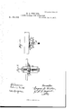
To all whom 'tt may concern Be it known that I, EUGENE D. WELLER, of Lima, in the county of Livingston and State of New York, have invented certain new and useful Improvement in Running-Gear for Ve hicles; and I do hereby declare that the following is a full, clear, and exact description of the construction and operation of the same, reference being had to the accompanying drawings, in which Figure 1 is a plan with the wagon-body and side bars removed from place. Fig. 2 is a longitudinal vertical section. Figs. 3', 4, 5, 6, 7, and 8 are detail views. Figs. 9 and 10 are modifications.
In general construction this invention is similar to that patented by me August 19, 1873, and is an improvement upon the same.
The invention consists in the construction and arrangement of the parts hereinafter described and specifically claimed.
In the drawings, A A represent the axles. B is the bolster. C O are the side springs, and D D are the side bars, resting on top of the springs and supporting the wagon-body. E E are half-perches, made fast at the rear and front, respectively to the axle and bolster, and jointed centrally or intermediately to bearings made fast to the side springs. Four of these half-perches are used, (two on each side,) corresponding in position with the ordinary stiff reaches of a double-reach carriage.
F F, Figs. 1, 3, and 5, are blocks attached centrally on top of the side springs by single bolts a. G G are the bearing-plates for the attachment of the half-perches. These plates are formed separate and independent from the blocks F F, but are attached to the latter by two bolts, b b, passing bodily through the the blocks, having heads j j on one side, and nuts k k on the other. The outer edges of the blocks are countersunk or notched in to seat the heads flush with the block,as shown in Figs. 3 and 5. The plates G are provided with one or more sets of holes, 0 c, and also with the bearing-journal d, to receive the ends of the half-reaches. When the plate G has one set of holes, they are located out of line with the bearing, so that the bearing may be made to project above or below the spring by simply inverting the plate, the same holes answering for the attachment to the block F, as before described. The successive sets of holes, more than one set, are all upon the same side of the bearing, and at any desired distance apart. The desired adjustment in height of the perches is thus obtained by simply inverting the plate G. The object of this adjustment is to enable the perches to maintain a substantially horizontal position under difi'erent weights of load.
The bearing (1 is extended sufiiciently to take the ends of both hali'perches. It is made conical as far as the thickness of the first perch E, fitting upon it, and then is made straight the remainder of the distance, to receive the second perch and the nut. The ends of the perches are halved or notched in the form of a rule-joint, as shown in Fig. 3. The outside edge of the outer reach has a socket, f, formed in it, in which rests a rubber, metal, or other spring, the whole secured by a nut, t. The pressure of the spring will constantly bear the ends of the perches upon the bearing, thereby preventing rattling.
I I are solid shackle-heads, clipped, bolted, or otherwise attached to the axle at the rear and the bolster in front. These serve as the attachment for the side springs. The heads of the shackles are first bored with a straight hole, to admit the passage of the bolt. are then countersunk or reamed out on each side in conical form, to receive the cones of the half-links, as will presently be described. The eyes G O of the springs are similarly prepared, by first boring the straight hole, and then countersinkin g on each side. To enable this to be done, said eyes are formed by bending the ends of the steel around iron center-pieces, and welding the whole together. This leaves a soft center, which can be bored, which could'not be done if the whole eye were solid steel. It also secures greater strength, with less danger of separation than where the steel is simply bent around.
K K are the half-links, of which one is used on each side. Each of these half-links has two hollow cones, l l, which enter the countersunk conical holes in the shackle and springeye, just described. When in place they reach nearly to the center. They are secured by bolts m, headed on one end and provided They with nuts n 'n on the other, by which the halflinks are tightened closely up to place, making a close joint and preventing any looseness or rattling. The half-links are formed separate, so as to be case-hardened, by which great hardness and long wear are secured. The cones of the links take all, or nearly all, the strain, since they form the hearings in the eye and shackle. The bolts, therefore, receive but little strain and serve simply to hold the parts together.
The double-join ted shackles are necessary to allow the perches to be adjusted higher or lower, since the ends of the perches rest upon the same center. In adjusting hi gheror lower the perches must be drawn in or let out. The shackles compensate for such movement.
L L are adjustable plates or stifieners to the springs used on each side at the rear or'front. They consist each of a strip of metal extendin g from the side bar or body bearing forward and back a suitable distance over the spring. At the inner end the plate rest-s closely between the side bar and spring at their junction, so as to have a bearing there. It also has a lug, p, which is attached to the inside of the side bar by a bolt, g. This bolt makes the attachmeut a fixture to the side-bar at its'inner end. At the outer end the plate has two or more holes, 7 1', through which passes a bolt,s, securing this end to the bottom of theside'bar.
From the inner end the plate extehds outward over the spring the desired Iength'to produce the contact-bearing, as shown at t, and from this point it turns up to meet the side bar, as shown at u. When ressure is applied upon the carriage, the plate gradu ally closes down upon the spring from the inner to the outer end of the length t, thereby stiflening the spring to that extent. By shifting the bolts to one or another of the holes 1* r the plate will be more or less straight ened, and consequently it will be more or less remote from the spring. By this adjustment the spring can be stiffened at any point of depression desired.
In Figs. 9 and 10 are shown devices'equivalent to the reversible bearing-plates G for adjusting the half-perches higher or lower. In this case the plate G is made of considerable length, andt-he bearing disattached'to a bar, '1), which is adjusted up and down by a screw shaft, w, which passes through the bar. The
bar is secured fast at any adjustment by headed bolts :10 m with nutsz z, as shown.
I do not claim, broadly, a'shackle-coupling with separate cones entering the countersunk sides of the spring-eye.
What 1 claim herein as new is-- l. The blocks]? and plates G, formed sepaarately and connected by bolts b 12, passing bodily through the' blocks,;aan'd having heads vided withthe coni'cal"or tapering portiorre,
and straight portion-j; of r the two half-perches, E E, resting thereon and connected by a rulejoint, as shown and described, and for the purpose specified.
4. The combination, with the countersunk shackle I andspring-eyelflflof the half-links K K, constructed with'fithe hollow case-hardened bearingcones l l, at opposite ends, entering thecoiiiitersink-s of'the shackle and spring-eye, and secured by the'holts mm and nuts n n, the whole-forming a double-jointedi shacklec0upling', as shown and described,
and for the purpose" specified.
5. The combinatiompwith" the side bar D and spring G, of theadjusting-plate L, fitted at one end between the sidebar and-spring, anil attached at the dtherend to the under side of thesidebar,-as shown and described, andforthe[fuiposespecifietli 6. Theadjiisting plate L,construeteja with the lug patentsnares-bolting the sameto the inside of the si'tlehar, and with two or moreholes;-r 1, atthe other end, for bolting to the bottom of thespring bar, as shown and described,-aud tor-thepuipose'specified;
Iu'witness-whereof I have hereunto sighed my name iii the presenceot two subscribing witnesses:
Di WELLER? Witnesses RaF- OSG' 'OD", nn'wm Sco'm.
Publications (1)
| Publication Number | Publication Date |
|---|---|
| US185992A true US185992A (en) | 1877-01-02 |
Family
ID=2255400
Family Applications (1)
| Application Number | Title | Priority Date | Filing Date |
|---|---|---|---|
| US185992D Expired - Lifetime US185992A (en) | Improvement in running-gear for vehicles |
Country Status (1)
| Country | Link |
|---|---|
| US (1) | US185992A (en) |
-
0
- US US185992D patent/US185992A/en not_active Expired - Lifetime
Similar Documents
| Publication | Publication Date | Title |
|---|---|---|
| US185992A (en) | Improvement in running-gear for vehicles | |
| US198298A (en) | Improvement in wagon-springs | |
| US747531A (en) | Vehicle running-gear. | |
| US185993A (en) | Improvement in running-gears for vehicles | |
| US157430A (en) | Improvement in springs for vehicles | |
| US373505A (en) | Running-gear for vehicles | |
| US115797A (en) | Improvement in wagons | |
| US761690A (en) | Frame for automobiles. | |
| US128211A (en) | Improvement in wheels for light vehicles | |
| US554534A (en) | Wagon-gear | |
| US255288A (en) | Head-block for side-bar buggies | |
| US277186A (en) | William s | |
| US220347A (en) | Improvement in spring-vehicles | |
| US816852A (en) | Running-gear for vehicles. | |
| US36050A (en) | Improvement in railroad-car springs | |
| US64501A (en) | Thomas de witt | |
| US472518A (en) | Spring-vehicle | |
| US131728A (en) | wither of gbicago | |
| US1093755A (en) | Axle-truck of railway and tramway vehicles. | |
| US413888A (en) | Wag on-gear | |
| US321587A (en) | Side-bar vehicle | |
| US166693A (en) | Improvement in king-bolts for vehicles | |
| US451029A (en) | Two-wheeled vehicle | |
| US141905A (en) | Improvement in vehicles | |
| US220204A (en) | Improvement in platform-gears for vehicles |