US1859906A - Brake mechanism - Google Patents
Brake mechanism Download PDFInfo
- Publication number
- US1859906A US1859906A US383480A US38348029A US1859906A US 1859906 A US1859906 A US 1859906A US 383480 A US383480 A US 383480A US 38348029 A US38348029 A US 38348029A US 1859906 A US1859906 A US 1859906A
- Authority
- US
- United States
- Prior art keywords
- chain
- lever
- link
- brake
- brake mechanism
- Prior art date
- Legal status (The legal status is an assumption and is not a legal conclusion. Google has not performed a legal analysis and makes no representation as to the accuracy of the status listed.)
- Expired - Lifetime
Links
Images
Classifications
-
- B—PERFORMING OPERATIONS; TRANSPORTING
- B61—RAILWAYS
- B61H—BRAKES OR OTHER RETARDING DEVICES SPECIALLY ADAPTED FOR RAIL VEHICLES; ARRANGEMENT OR DISPOSITION THEREOF IN RAIL VEHICLES
- B61H13/00—Actuating rail-vehicle brakes
- B61H13/20—Transmitting mechanisms
-
- Y—GENERAL TAGGING OF NEW TECHNOLOGICAL DEVELOPMENTS; GENERAL TAGGING OF CROSS-SECTIONAL TECHNOLOGIES SPANNING OVER SEVERAL SECTIONS OF THE IPC; TECHNICAL SUBJECTS COVERED BY FORMER USPC CROSS-REFERENCE ART COLLECTIONS [XRACs] AND DIGESTS
- Y10—TECHNICAL SUBJECTS COVERED BY FORMER USPC
- Y10T—TECHNICAL SUBJECTS COVERED BY FORMER US CLASSIFICATION
- Y10T74/00—Machine element or mechanism
- Y10T74/20—Control lever and linkage systems
- Y10T74/20558—Variable output force
Definitions
- This invention relates to brake mecha nism of the typewherein the initial stage of operation effects a quick take up of slackv j and is followed by a powerful application of the brakes. f Its principal objects are to reduce the cost of manufacture by using chains or chain sections of different weight, and to provide simple and efiective connections between the 1 chains andthe sheave or lever device, whereby movement of the brake staff is differential- 1y applied to the brakes 'in'the successive stages of operation.
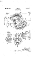
- Fig.1 is a semi-diagrammatic front eleva tional view of a reversible lever constructed '25 in accordancewith this invention and asso- V ciated with conventional forms of foundation brake gear and hand brake mechanism.
- Fig. 2 is a fractional,elevational View of the levertaken on the line 22 of Fig. 1.
- Fig. 4 is a semi-diagrammatlc view of the reversible lever in theposition assumed when 3 power is being'app'liedto the brakes 1
- the reference character designates generally'a reversible lever or; cam constructed substantially in accordance with the teachings of the patents to H. I.
- the lever 10 is diagrammatically shown in its operative'relation :to conventional forriisfof foundation brake geara'nd hand brakes; the foundation brake gear, generally designated 11, being actuated by the air brake cylinder 12, which-im- "parts'in'ovement to the live cylinder lever13,.
- the brake 81165 1 acting through intermediate levers and the power'chain 17 are employed to cooperate-with the reversible lever for securing Twofoperating chains, which fo-r co'nven- 'ience will bereferred to as the slack chain 16' a'quick take up 'of s'lack followed by a power ful braking action.
- the reversible lever 10' is fulcrurned at21 to a jaw or yoke 22 which in turn is connected to the foundation brake gear 11 by the hand brake rod 23;
- the fulcrum 21 divides the lever lO into a short arm 24 and a long arm 25,-the short arm being curved eccentric to the fulcrum 21, and the long armbeing some what similar to a segment in form.
- Theright edge 27 (Fig. 1) of the segment or long arm has" a flat surface,and is provided with a projection28 having a longitudinal or vertical slot 29and atransverse slot 30.
- The'outer edges oftheprojection'1 are shouldered as atf31' to forma pocket for, I
- a recess 32 Adjacent the end of" the projection 2 8-a'nd in the edge' face 27 of the segment or long arm 25 is a recess 32 having atransversebore "33 in its wallsia'dapt'e'd to receive a pin or V Jcotter31j "j' In Fig.
- the lthe reversible lever'10 is shown in the position assumed when the'brakes are v I released, while in Fig; 4; the leverf10 is shown in the position assumed when power is'jbeing applied to the brakcs-f ltqwill be seen that during the first st'age of the; braking operalOO H' tion when the slack is being taken up, there is relatively little stress on the operating chains, but when the slack has been accounted for. and the brakes are being applied (as shown in Fig. 4), the unit stress in the power chain l7 is much greater than thatin the slack chain-1 6 dueto the difference in lengths of the two arms of the lever 10. Taking advantage of this difference in unit stress, the
- slack'chain16 is made up of links' of smaller cross section than those in the' power chain 17, as shown most clearly in Fig. 3, thereby resulting in a saving in material and're'sult ing in a reductionin the cost of manufacture.
- a reversible lever in a brake mechanism, a projection on one face, slotted, to receive adjacent links of an operating chain, and means for locking said links in place by a second operating chain anchored to the lever.
- a reversible lever having a groove in its periphery to receive an operating chain, means. associated, with said groove for exteriorly engaginga link of the operating chain, and means comprising an abutting link of asecond chain for preventing disengagement of thefirst named chain.
- a reversible lever having a grooved periphcry, a; projection on one. edge taceiofthe lever having open, longitudinaland transverse slots,.a recess. in said face ad acent the end of said roection a ower chainassociscr bed has been designed to reduce manutacp 1 p tuning cost by the employment of two chains ated with: the grooved periphery and having its adjacent endlinks engaged in the slotted projection, and a slack chain associated with the grooved periphery and'anchoredin the said recess, the end link of said slack chain abutting the end link of the power chain and.
- T 7 In a brakermechanism, a reversible lever having a relatively deep link-receiving JACK 7 WILSON.
Landscapes
- Engineering & Computer Science (AREA)
- Mechanical Engineering (AREA)
- Braking Arrangements (AREA)
Description
May 24, 1932. J. WILSON BRAKE MECHANISM Filed Aug. 5, 1929 iii lief Jaab Wilson Patented May 24, .1932
UNITED STATES Jeox WILSON, or CHICAGO, ILLINOIS, AssIeNd t'ro I IvEI 'saI. DRAFT names. 1
PA ENT] lorries MENT 00., OF CHICAGO, ILLINOIS, ACORPORATIQNDF I LI vO-Is BRAKE MECHANISM This invention relates to brake mecha nism of the typewherein the initial stage of operation effects a quick take up of slackv j and is followed by a powerful application of the brakes. f Its principal objects are to reduce the cost of manufacture by using chains or chain sections of different weight, and to provide simple and efiective connections between the 1 chains andthe sheave or lever device, whereby movement of the brake staff is differential- 1y applied to the brakes 'in'the successive stages of operation.
These objects are accomplished in the em- Fig.1 isa semi-diagrammatic front eleva tional view of a reversible lever constructed '25 in accordancewith this invention and asso- V ciated with conventional forms of foundation brake gear and hand brake mechanism.
"Fig. 2 is a fractional,elevational View of the levertaken on the line 22 of Fig. 1.
' 30 i Fig. 3is a sectional view taken on the line 33 of Fig. 1 and looking in the direction of the arrows; and j 1 I Fig. 4 is a semi-diagrammatlc view of the reversible lever in theposition assumed when 3 power is being'app'liedto the brakes 1 Referring to Fig; 1, the reference character designates generally'a reversible lever or; cam constructed substantially in accordance with the teachings of the patents to H. I.
4 WrigleyNo. 1,567,407 and P. B. Camp et a1 No. 1,543,470 ,but which differs from them in that the lever is adapted to be operated'by two chains "instead of one. The lever 10 is diagrammatically shown in its operative'relation :to conventional forriisfof foundation brake geara'nd hand brakes; the foundation brake gear, generally designated 11, being actuated by the air brake cylinder 12, which-im- "parts'in'ovement to the live cylinder lever13,.
't-herebyefi'ecting a braking action on the wheels ltb-ypressureof "the brake 81165 1 acting through intermediate levers and the power'chain 17 are employed to cooperate-with the reversible lever for securing Twofoperating chains, which fo-r co'nven- 'ience will bereferred to as the slack chain 16' a'quick take up 'of s'lack followed by a power ful braking action. 1 j a I One e ld Ofthe slack chain 16 isin winding engagement with the brake staff. 18"eq'uipped with a drum 19 for guiding thechain: up
wardly along'the staff, and the'correspond ing end of the'power'chain 17 is anchored-in any suitable manner to some fixed member 20 ofthecarz'p 1 The reversible lever 10'is fulcrurned at21 to a jaw or yoke 22 which in turn is connected to the foundation brake gear 11 by the hand brake rod 23; The fulcrum 21 divides the lever lO into a short arm 24 and a long arm 25,-the short arm being curved eccentric to the fulcrum 21, and the long armbeing some what similar to a segment in form. The entire periphery of the lever 10, except for one face, is groovedas at 26- for' co-operating with the operating 'chain sif A more detailed description of the;peripheral outline of' the lever may be found in the patents to Wrig ley and Camp, referred toqsupra', as well as a description of the manner in which the le- 7 ver operates to accomplish the differential braking action.
Theright edge 27 (Fig. 1) of the segment or long arm has" a flat surface,and is provided with a projection28 having a longitudinal or vertical slot 29and atransverse slot 30. The'outer edges oftheprojection'1 are shouldered as atf31' to forma pocket for, I
achain link. I
Adjacent the end of" the projection 2 8-a'nd in the edge' face 27 of the segment or long arm 25 is a recess 32 having atransversebore "33 in its wallsia'dapt'e'd to receive a pin or V Jcotter31j "j' In Fig. lthe reversible lever'10 is shown in the position assumed when the'brakes are v I released, while in Fig; 4; the leverf10 is shown in the position assumed when power is'jbeing applied to the brakcs-f ltqwill be seen that during the first st'age of the; braking operalOO H' tion when the slack is being taken up, there is relatively little stress on the operating chains, but when the slack has been accounted for. and the brakes are being applied (as shown in Fig. 4), the unit stress in the power chain l7 is much greater than thatin the slack chain-1 6 dueto the difference in lengths of the two arms of the lever 10. Taking advantage of this difference in unit stress, the
slack'chain16 is made up of links' of smaller cross section than those in the' power chain 17, as shown most clearly in Fig. 3, thereby resulting in a saving in material and're'sult ing in a reductionin the cost of manufacture.
In anchoring the chains 16 and 17 to the lever 10 the two adjacent'end links 35 and 36 of the chain 17 are brought; into engage+ .ment with'the projection 28, the link 35 enthe groove 26 of the periphery ofthe lever 10.
By this construction, it will be seenthat the end link 37 anchored to the lever 10 in the recess 32 abuts-against and securelylocks the link 36-01? the power chain 17 in the pro jection- 28, thus providing a simple, yet strong, durable and efficient means'for interlocking the operating chains tothe cam lever.
It willbe noticed that one of the'cardin'al advantagesfof this novel anchor construction rests in the fact that the cotter orpin 34 carries but a I small portion of the actual stress acting upon the lever 10 through the chains 16 and 17.. V
-No exact analysis ofthe distribution of stresses need be indulged in for it'will readily be seen that the tension in the chain 17 is carried largely by the projection 28 assisted, at certain stages of the braking operation,
7 by a downward pressure (Fig. 1) of the link 36 upon the link 37 while the tension in; the chain 16,.when at its maximum (Fig. 4) is principally carried by the edge 27 and the projection 28 through a lever action of the link 37 against the link 36.
'Although the reversible lever here deof different weight and strengthglt is obvious that a single chain may be employed, if desired, in place of the slack chain 16 and the the selected embodiment herein described for the purpose of illustration, without departing from the spirit of the invention as expressed in the appended claims forming a part hereof.
What I claim is: r
1. In brakemechanism for railway cars and the like, a reversible lever tulcrumed to form a long arm and a short arm, a projection on one edge face and having open slots at substantially right angles to each other slotsfordetachably engaging. the adjacent end links of a relatively heavy power chain,
areces's inlthe peripheryofthe said face and adjacent the end of the projection for receiving the end'link of a relatively light slack chain,.and means for anchoringthe said end link in the recess, said end link serving to lock the adjacent end links 'ofthe first'named I chain in the slots, of theprojection. i
3. In a brake mechanism, a reversible lever a projection on one face, slotted, to receive adjacent links of an operating chain, and means for locking said links in place bya second operating chain anchored to the lever.
4. In a brake mechanism, a reversible lever having a groove in its periphery to receive an operating chain, means. associated, with said groove for exteriorly engaginga link of the operating chain, and means comprising an abutting link of asecond chain for preventing disengagement of thefirst named chain.
v5.. In a brake mechanism, a reversible le- 6, In a brake mechanism for railway cars,
a reversible lever having a grooved periphcry, a; projection on one. edge taceiofthe lever having open, longitudinaland transverse slots,.a recess. in said face ad acent the end of said roection a ower chainassociscr bed has been designed to reduce manutacp 1 p tuning cost by the employment of two chains ated with: the grooved periphery and having its adjacent endlinks engaged in the slotted projection, and a slack chain associated with the grooved periphery and'anchoredin the said recess, the end link of said slack chain abutting the end link of the power chain and.
preventing its disengagement from the projection. T 7 In a brakermechanism, a reversible lever having a relatively deep link-receiving JACK 7 WILSON.
Priority Applications (1)
| Application Number | Priority Date | Filing Date | Title |
|---|---|---|---|
| US383480A US1859906A (en) | 1929-08-05 | 1929-08-05 | Brake mechanism |
Applications Claiming Priority (1)
| Application Number | Priority Date | Filing Date | Title |
|---|---|---|---|
| US383480A US1859906A (en) | 1929-08-05 | 1929-08-05 | Brake mechanism |
Publications (1)
| Publication Number | Publication Date |
|---|---|
| US1859906A true US1859906A (en) | 1932-05-24 |
Family
ID=23513353
Family Applications (1)
| Application Number | Title | Priority Date | Filing Date |
|---|---|---|---|
| US383480A Expired - Lifetime US1859906A (en) | 1929-08-05 | 1929-08-05 | Brake mechanism |
Country Status (1)
| Country | Link |
|---|---|
| US (1) | US1859906A (en) |
Cited By (1)
| Publication number | Priority date | Publication date | Assignee | Title |
|---|---|---|---|---|
| US3194357A (en) * | 1963-02-25 | 1965-07-13 | Girling Ltd | Means for adjusting vehicle brakes |
-
1929
- 1929-08-05 US US383480A patent/US1859906A/en not_active Expired - Lifetime
Cited By (1)
| Publication number | Priority date | Publication date | Assignee | Title |
|---|---|---|---|---|
| US3194357A (en) * | 1963-02-25 | 1965-07-13 | Girling Ltd | Means for adjusting vehicle brakes |
Similar Documents
| Publication | Publication Date | Title |
|---|---|---|
| US1859906A (en) | Brake mechanism | |
| US1928630A (en) | Brake | |
| US1612781A (en) | Foundation brake rigging | |
| US1831335A (en) | Brake lever construction | |
| US1545992A (en) | Hand-brake mechanism for railway cars | |
| US2166256A (en) | Hand brake mechanism for railway cars | |
| US286127A (en) | Automatic car brake | |
| US2196242A (en) | Car brake | |
| US1652759A (en) | Bbake mechanism foe eailway caes | |
| US1500217A (en) | Brake rigging for railroad cars | |
| US1405665A (en) | Reversible-strut brake beam | |
| US1698728A (en) | Hand brake | |
| US1919184A (en) | Brake operating mechanism | |
| US1168716A (en) | Hoisting-drum and brake for the same. | |
| US1623227A (en) | Brake mechanism | |
| US1517616A (en) | Winch | |
| US1680336A (en) | Hand brake | |
| US1752704A (en) | Railway brake equipment | |
| US974004A (en) | Automatic brake-adjuster. | |
| US2090100A (en) | Brake construction | |
| US1558840A (en) | Brake mechanism for railway cars | |
| GB282920A (en) | Improvements in, or relating to, the brakes of motor vehicles | |
| US1805805A (en) | Clevis for brakes | |
| US1740545A (en) | Empty and load brake | |
| US1679403A (en) | Quick take-up and release hand brake for railroad cars |