US1859905A - Testing apparatus - Google Patents
Testing apparatus Download PDFInfo
- Publication number
- US1859905A US1859905A US484944A US48494430A US1859905A US 1859905 A US1859905 A US 1859905A US 484944 A US484944 A US 484944A US 48494430 A US48494430 A US 48494430A US 1859905 A US1859905 A US 1859905A
- Authority
- US
- United States
- Prior art keywords
- relay
- test
- selector
- line
- conductors
- Prior art date
- Legal status (The legal status is an assumption and is not a legal conclusion. Google has not performed a legal analysis and makes no representation as to the accuracy of the status listed.)
- Expired - Lifetime
Links
Images
Classifications
-
- H—ELECTRICITY
- H04—ELECTRIC COMMUNICATION TECHNIQUE
- H04M—TELEPHONIC COMMUNICATION
- H04M3/00—Automatic or semi-automatic exchanges
- H04M3/22—Arrangements for supervision, monitoring or testing
- H04M3/26—Arrangements for supervision, monitoring or testing with means for applying test signals or for measuring
- H04M3/28—Automatic routine testing ; Fault testing; Installation testing; Test methods, test equipment or test arrangements therefor
- H04M3/30—Automatic routine testing ; Fault testing; Installation testing; Test methods, test equipment or test arrangements therefor for subscriber's lines, for the local loop
Definitions
- This invention relates to testing arrangements 1n general, particularly to testing arrangements vfor use 1n automatic telephone SYS'CQIHS'flIlCl is concerned primarily with im-- 5 proved apparatus and j c1rcu1ts for extending a connection from a test switchboard'to a subscribers line terminating in an automatic s s accompanying single figure of drawing. 1
- the embodiment of the invention inatelephone system in'which ;eXchange.
- An object of the present invention is the provision ofan improved arrangement whereby test connections may be extended in part over exchange switching apparatus such as is ordinarily provided for local and toll service without requiring any changes or modifications whatever in such apparatus;
- This object is attained by providing a simple test selector adapted to operate with the standard test switchboard circuits, the selector being grouped with the regular battery feedingselectors of the exchange and having access in' .more complicated I or in a different ofiice.
- test cord TC of which only 'a-part i's-showmmaybe similar to-the test cord disclosed inUnite d States Patent No. 1,691,269 to iCrockenof sociated with the usual testing'devi'ces; in
- test trunks such as the-one extending from the. m
- loto test selector TS which incidentallvmayzie from the connector in-localiconnections and from a selector in tollc0nnections, such for example as the system disclosed in'United States Patent No. 1,786,04Ll ,”granted Dec, 23,
- the inter- 9 7 v 'mediate selectors in turn have access to the various connectors of the system, such as connector O which has access to different subscribers lines including that extending to substation T; 'It will be noted that the test selector is arranged to connect with the inshown only in skeleton form since these switches may be exactly the same as the corresponding switches shown: in fithe' zpreviously referred to Wicks application; Serial No.
- relay 33 operates "over the previously described 4 loop which includescontacts' 21 and conducftors 29 and 3E completes a 'circuit"fro1n groundat” con tacts- 55, winding of relay 34:, windings of "relay 35 to battery, and in 1 parallel therewith "through release magnet contacts, contacts '79, winding of vertical inagnet-40, toba ttery.
- Relay 33 also closes a circuit "for ⁇ relay 36by way or contacts "52566 and 74, resistance 48, to ground. *Relay 34:
- contacts 14' close and complete a circuit for relay 5.
- Relay 5 operates, disconnects the ring and tip conductorsof the cord circuit' from the testing apparatus and connects them to the impulse contacts of the dial at contacts 23 and 25, andat contacts 26 disconnects ground trom thesleeve ofthe plug.
- Relay-1 oi the trunk circuit restoresduc to the removal of ground from the sleeve and switches control conductorsfl) and-32 ofthe trunk through to the tipand ring springs-of ,thegjack.
- Relay-33 of the'test selector isnow held operated over a controlloop-whi-ch includesthe impulsing contacts 15 of the callng devlce.
- Calling device CD on returningto'normalinterrupts the loopcircuit at] contacts 15 in accordance with the number dialled, and relay 33 respends -'accordingly 'by --'deenergizing' and reenergiiing.
- "Each time relay 39w deenergizcs*a circu'it is closed from ground "at contacts 57, contacts 54,
- Relay 34 is slow to release due to its winding being short circuited-"at contacts L54 and "remains operated during 5 impulsing, "Relay 35'also"remalns energized throughout series of impulses" being slow-to-release, due
- relay 35 restores shortly after the last impulse ofthe ser1es-and, since ofi-non' mal contacts 44 have closedkon theiirstWr- *tical step of the "wipers, a CHC'Lllt .1s "C0111- "pleted'forrotarv magnet dl 'by-way of con- "tacts '61 and 77 and interrupter contacts'8l 'I/Jiagnet; 4:1 energizes, rotates the wipers one step and nterrupts its own. circuit-at contacts "81. "This operation will "be repeated until test wiper 84 encounters an rdletrunk,
- each seriesof impulses a temporary holdlng c1r-' cui't forthe relay is completed by way of con tacts53, resistance 50,.a'nd contacts 56.
- the line ipers 82 and 85 are connected to the control conduc-' tors'of the switch and the original energizing circuit of relay 36 is opened at contacts 74:.
- Relay 36 remains energized, however, over a wiper 85, contacts 80 and 69, to grounch
- the impulse relay of the 'intermediatei selector energizes in serieswith relay 36 and prepares the selector for operation.
- lay 33 of the test seclector responds as before, and with each deenergization interrupts the loop circuit for the impulse, relay of the intermediate selector at contacts 52.
- Relay 35' again operates during the series of impulses buthas no effect at this time. It willbe noted, however, that the upper winding of relay 35 is now short-circuited by way of contacts 78 and the release magnet contacts.
- battery is a connected to the upper wiper and ground to the lower wiper so that battery flow over the connection will be in one direction in local calls andin the opposite direction intest-call's.
- This arrangement isfor-the purpose of operating a polarized relay which is connected in series with the impulse relay of the connector.
- This polarized relay on operating prepares the connector for toll operation by 65 preparing the special test circuit and by looking up the ring-cutoff relay of the: con
- the second and "third digits "tie" aw dialled. -The test'selector repeats these series of impulses in'the same manner as'in the'case ofthe second series of impulses, and the Wipers of connector G are operated into-en ga'gement with thecontacts associatedwith the wanted subscribers li' e, that is, the line 1 comprising conductors 94'96.
- test selector restores and contacts 591and7lconnectsbattery via resist- ..ance 14:6 to: the; conductor. instead.
- the .value ofresistance-46 is suchothat the wiper closing relay. ofthe connector willoperate and switch .the connection through in the :usual way.
- a test switchboard Ina telephone system, a test switchboard, a'trunk line comprising operating conductors' and test conductors terminating in the switchboard, automatic switches means controlled from theswitchboard for operating said switches to establish a connection with a subscribers line independent of said 7 test conductors,and means responsive to the establishment of the connection withsaid line for including said vtest conductors in the connectiom V 7 .4.
- atestswitchboard, a test selector, other automatic switches-means controlled from the switchboard for operating saidjselector and said other switches'to establish a clear metallic circuit between the selector and a subscribers-line, and automatic means responsive to the establishment.
- a test switchboard In a telephone system, a test switchboard, a test selector, other automatic switches, a trunk line comprising operating conductors and test "conductors extending from theswitchboard to said selector, means controlled over said operating conductors for 5 operating said selector and said other switches to complete a clear metallic circuit between the selector and a subscribers line, and automatic means including a relay controlled by said other switches for connecting said circuit to said test conductors.
- a trunkline comprising operating con-j ductors and test conductors, va test selector and a connector, meansicontrolled over said operating conductors for operating said selector to seize said connector, a control'circuit extending from the selector to the connector, means in the selector controlled over '1 saidoperating conductors for interrupting said circuit to transmit digitllimpulses, a relayin the connector responsive tosaid impulses for; setting the connector on a subscribers line, and meansin the selector responsive to the connector engaging 'sai'dline for extending the .controlcircuitto the test switchboard viasaid test conductors.
- a trunk line comprising operating conductors and test conductorsfa test selector and a connector, means controlled over said operating conductors for operating sa d selector to seize connector, a control circuit ex-" of current to said. circuit, means in the se-' the connector responsive to said impulsesforline for disconnecting saidbridge and for es- 1 "pleting a test connectioncomprisin'g a clear ,6.
- a test switch board, a toll switchboard, means including a, I. SGIGCtOIIBPGatQIEaIld a connector for extend-1 ing a talking connection from ls'aid t toll switchboard to a subscribers line, "and means including another selector repeater and said,
- al 'selectorire b I lector repeater means controlled overfthef operating conductors of saidfirst trunk line for operatingsaid selector repeaterto'jc'onnect a i! ,connector' iorcompleting a test connection.
- an. automatic switch a trunk line comprising two-pairs of V conductors terminating-in said 'switch, asecnd trunk line including a pair of conductoirs accessible to said SW1tCh,' means controlled over one pair of conductors of sa d lirsttru-nk line for operating said switch-to connectwitlr;
- said second trunk line means-insaidswitch iorconnecting abridge-across the conductorsofsaid second trunk line and for inter-rupt ing said bridge to transmit-impulses over the,
- an automatic switch a trunk line comprising, operating conductors and test conductors terminating in said switch, a trunk line; including opera ating'conductors accessible to 1 said switch, means controll ed 1 over the operating con u t r f s rst t n ne e con r in said SWltChf tO connect with said secontl trunli line and for then transmitting impulses oyer the operating conductors of 'saidsecondjtrunk l ne t ico ne s i asubscribie'rfs e, n s aid wit lll i spbnsive.
- ductersbfs id line for completing a direct'connecti-on be tween the operating conductorsof said second trunkline and the test conductors of -said'fi-rst trunk-line.
- a trunkv line comprising. two ipalrst of conductors. terminating in; onelofasaidl V switches, meanscontrolled oyersthe. firstzpair; ofconductors of saidtrunk lineffor.
- switch means. in said-one switchacontrolled; over the first 7 pan: of conductors "of; said trunk. line for transmitting impulses; over,
- said externali circuit to set: saidsucceeding switch, m'eans for opening'said eXternalsci-r cuit at. the completionoi' the operationiof said succeeding switchito deenerg'ize said zres.
- tors normally terminatinglin'the springso-f a .manual jackiat: one end-and inrthelimpulse relay-..of an 'automaticswitch at the other end and said test conductors being normally open at both .ends, meansa-responsive to the establishmentdof a connection with said trunk lineivia said jack, for-connectingsaid test conductors to. the. jack springs: in: place ot said operating condiactorsand fen closing a. bridged across,- said/ operating conductors to operate said impulserelay, means; controlled over saidjack for temporarily restoring the.
- test connectiom- 19 In a telephone system, -subsori-bers lines,a tol-l switchboai'd, -a testzswitclrboardg a train of automatic switches, meansf 'reS- tablishing a talking:-connection-;between two" subscribers" lines I over i said R switch trail-1;,
- a subscribers I intermediate selector and said connector, and 1 line, a local selector, a toll selector, a testselector, an intermediate selector, a connector,
Landscapes
- Engineering & Computer Science (AREA)
- Signal Processing (AREA)
- Monitoring And Testing Of Exchanges (AREA)
Description
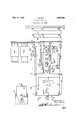
J. WICKS TESTING APPARATUS Filed Sept. 29, 1930 May 24, 1932.
FROM ZINE 5W FPOM T011 80 Jul-m wicks usrA'r-s I T EN CIATEI) ELECTRIC LABORATGRIES,INC., OF CHICAGO; ILLINOIS, A CORPORATION OF DELAWARE r TEsTiNGAPrARe'rus Application filed September 29,'193l). Serial 80.484 944. i
This invention relates to testing arrangements 1n general, particularly to testing arrangements vfor use 1n automatic telephone SYS'CQIHS'flIlCl is concerned primarily with im-- 5 proved apparatus and j c1rcu1ts for extending a connection from a test switchboard'to a subscribers line terminating in an automatic s s accompanying single figure of drawing. 1 In the drawing-theregis shown by means oif'the usual circuit diagrams, the embodiment of the invention inatelephone system in'which ;eXchange.
In systems of the above type routine tests 11) on subscribers lines are ordinarily made at a central test switchboardor wire chiefs testv desk. Special test trunks extend from the switchboard to each exchange in the system, and each exchange is provided with a special 15 test switch train for extending'connections to the subscribers line. A clear metallic circuit free of bridges andother connections is reouired for testin pur oses. Thisis the l A r main reason for providing the special test switch train, as the regular. exchange switcli-- 121g apparatus ordlnarlly used isnot adapted to provide such a circui Testing systems have been,v proposed in which test connections are extended, in part, over the I exchange switching apparatus. Heretofore systems of this type haverequired changes and modifications in" theexchange switching apparatus in order to provide a circuit that is suitable for testing purposes. Such arrangements are objectionable due to the increased cost and to the added difliculties in maintaining the equipment.
An object of the present invention is the provision ofan improved arrangement whereby test connections may be extended in part over exchange switching apparatus such as is ordinarily provided for local and toll service without requiring any changes or modifications whatever in such apparatus; This object is attained by providing a simple test selector adapted to operate with the standard test switchboard circuits, the selector being grouped with the regular battery feedingselectors of the exchange and having access in' .more complicated I or in a different ofiice.
common with these switches to the interme (hate selectors and connectors of. the eX- change: 1.
circuits involved,"reference being had to the talkingbattery is fed from a selector in both local and tollconnections. A telephone sys- September 28.1929. 1 It will-be appreciated JOHN WICKS, or 0A2: PARK, ILLINOIS, AssienoR, BY MESNEASSIGNMENTfiTO AssoQ The various featuresYo-f the, invention will i .be describedin detail in connection With-the description, of the 7 operation of "the ivarious that the invention may be. employed equally 1' Well to'systemsin which talking battery is 1930 to'Tharp and Wicks.
Referring now to the drawing, test cord TC, of which only 'a-part i's-showmmaybe similar to-the test cord disclosed inUnite d States Patent No. 1,691,269 to iCrockenof sociated with the usual testing'devi'ces; in
'dicated infth e drawing by a" dotted line, and
is adapted to connect with test trunks, such as the-one extending from the. m
associatedlwith the trunkline. and are loto test selector TS, which incidentallvmay pied from the connector in-localiconnections and from a selector in tollc0nnections, such for example as the system disclosed in'United States Patent No. 1,786,04Ll ,"granted Dec, 23,
November'l 3, 1928. .The cord circuitisasanual jack a 'J to test selector'TS. jTrunlrrelays TR are be located in the same-ofiiceas the test desk I The test selectorto gether with local'selectorrepeaters, such as the selector repeater-SR, and toll transmission selectors, suchas the selector TTS, have access to intermediate selectors of which one, namely, selector shown. The inter- 9 7 v 'mediate selectors in turn have access to the various connectors of the system, such as connector O which has access to different subscribers lines including that extending to substation T; 'It will be noted that the test selector is arranged to connect with the inshown only in skeleton form since these switches may be exactly the same as the corresponding switches shown: in fithe' zpreviously referred to Wicks application; Serial No.
By way of"illustration the operations involved in extending a connection f-romgthe testiswitchboard to'the subscribers line ter- 925 ."in'in'ating' in substation l will now be described; Pl-u'g lP, (if-the test cordTC is inserted in thejjackof an idle trunk for example, jackll, whereoncontacts 27 close and completeyacircuit forrelay 4. f-"Relay 4:, op-
' crates, closes a point "i-n the control circuit -at' contacts' 21" andprepares aholding circuit for itself in series-with relay 3 at contacts 20. "'Rlay'lpf thetrunk circuit operates over a V circuit exten ding byway of thesleeve offlthe fjae'lr'andplu'g, resistance 6, to groundat contactsQG. '"Relayl' on operating completes a llocpi circuit for operating relay 33 of the test select'orfby closing contacts 10,-and'by open-- 'ing-"conta-cts Tand I1 -and*closin'g contacts 8 P and 12,"the tip andring-springsof the jack are disconnected from the control conductors and: connected .to the test conductors of the trunk. Referring'nowto-test selector,relay 33 operates "over the previously described 4 loop which includescontacts' 21 and conducftors 29 and 3E completes a 'circuit"fro1n groundat" con tacts- 55, winding of relay 34:, windings of "relay 35 to battery, and in 1 parallel therewith "through release magnet contacts, contacts '79, winding of vertical inagnet-40, toba ttery. Relay 33 also closes a circuit "for {relay 36by way or contacts "52566 and 74, resistance 48, to ground. *Relay 34:
operates; but due "to its relatively high re- *sistance; neither the vertical -i'ma gnet nor relay 35 operate at this time. 'Relay'34' connects ground-to the local holding "circuit at V 1 contacts-56 prepare's' the 'impul'sin gcircuit at contacts "5' 7, andopensthe-releasehiagnet 'circuit'at contacts 58.; iRelay 36 now opcrates and opens "a point in the circuit of 'r'layF37 at contacts'62; v
'The foregoing operations take "placef'responsiveto the'insertion of the'plug of a test it cord into thejack'of'an idle trunkline, The
mom;
wire chief will now dial the first digit of the number designating the wanted line. When the calling device CD is turned OE-normal,
contacts 14': close and complete a circuit for relay 5. Relay 5, operates, disconnects the ring and tip conductorsof the cord circuit' from the testing apparatus and connects them to the impulse contacts of the dial at contacts 23 and 25, andat contacts 26 disconnects ground trom thesleeve ofthe plug.
Relay-1 oi the trunk circuit restoresduc to the removal of ground from the sleeve and switches control conductorsfl) and-32 ofthe trunk through to the tipand ring springs-of ,thegjack. Relay-33 of the'test selector isnow held operated over a controlloop-whi-ch includesthe impulsing contacts 15 of the callng devlce. Calling device CD on returningto'normalinterrupts the loopcircuit at] contacts 15 in accordance with the number dialled, and relay 33 respends -'accordingly 'by --'deenergizing' and reenergiiing. "Each time relay 39w deenergizcs*a circu'it is closed from ground "at contacts 57, contacts 54,
througlrt'hewindingsof rel'ay' 3i ,to battery,
and by'way of the release magnet contacts "and contacts '79, through the-wind 1g of vertical magnet 4E0 tovbattery. Both the relay "and the magnet operate under these aconditions'and the Wiperso'f the selector areiraised one step. Relay 34 is slow to release due to its winding being short circuited-"at contacts L54 and "remains operated during 5 impulsing, "Relay 35'also"remalns energized throughout series of impulses" being slow-to-release, due
'to its series connection with relay 3%. *Ait the'end ofthe series of impulses contactsl-t oi the 'CELllIDgIdQVKZQ' Will again open and re- *l'ay will restore thereby reconnectingthe ltest apparatusto the: ring andtip conductors pofthe'cord. Ground onthesleeve reoperates relayl and the holding loopfor relay 33 is again closed'at 'contactsl0. In the test 7 selector, relay 35 restores shortly after the last impulse ofthe ser1es-and, since ofi-non' mal contacts 44 have closedkon theiirstWr- *tical step of the "wipers, a CHC'Lllt .1s "C0111- "pleted'forrotarv magnet dl 'by-way of con- "tacts '61 and 77 and interrupter contacts'8l 'I/Jiagnet; 4:1 energizes, rotates the wipers one step and nterrupts its own. circuit-at contacts "81. "This operation will "be repeated until test wiper 84 encounters an rdletrunk,
"which is'marked .by the presence of battery potential on the test conductor corresponding to conductor 88. When an idle trunk is encountered relay 39 w ll operate over its upper wlnding and open the circuit of the rotary magnet at'contacts 'i'i, thereby stopp ng the rotary fmovement of the QWlPG-ISf I'Relay 39 completes a'locking circuitfor its lower winding in series with the rotarymagnot by closing contacts 76, and short-circuits its upperwindingat contacts 7510 marh'the seized trunk line busy by "connecting direct 'groundthereto. It will be recalled that relay 36was energized'when the switch was seized. During the transmission of? each seriesof impulses a temporary holdlng c1r-' cui't forthe relay is completed by way of con tacts53, resistance 50,.a'nd contacts 56. Upon the'operationof relay 39 the line ipers 82 and 85 are connected to the control conduc-' tors'of the switch and the original energizing circuit of relay 36 is opened at contacts 74:. Relay 36 remains energized, however, over a wiper 85, contacts 80 and 69, to grounch The impulse relay of the 'intermediatei selector energizes in serieswith relay 36 and prepares the selector for operation.
The wire chief will now dial the next digit or" the number whereon the switching opera,-
tionsin the cord and trunk circuits take place as forthe previousdigit. Impulsere:
lay 33 of the test seclector responds as before, and with each deenergization interrupts the loop circuit for the impulse, relay of the intermediate selector at contacts 52. Relay 35' again operates during the series of impulses buthas no effect at this time. It willbe noted, however, that the upper winding of relay 35 is now short-circuited by way of contacts 78 and the release magnet contacts.
.Thisis for the purpose of increasing. current 'za flow in the circuit of release relay 34: to insure the complete energization of that relay: 1 The p the foregoing that 'thereis now 'a' clearjme- 'tallic oircuitfrom the testing apparatus at I impulse relay of the intermediate selector responds to the impulses in the usual Way and the wipers oi" the switch are' raised to the called'level Whereonthey are rotated over the impulse relay of connector 'C which operates. V
It was previously mentionedthat the upper Wiper of test selector TS'connected with'the upper trunk conductor whereas the upper 'Wiper of a local selector repeater, such as SR,
connected with the lower talking conductor of the trunk. In both selectors, battery is a connected to the upper wiper and ground to the lower wiper so that battery flow over the connection will be in one direction in local calls andin the opposite direction intest-call's.
This arrangement isfor-the purpose of operating a polarized relay which is connected in series with the impulse relay of the connector. This polarized relay on operating prepares the connector for toll operation by 65 preparing the special test circuit and by looking up the ring-cutoff relay of the: con
nector to preventringing cur-rent from'belng applied to the calledf line.
The second and "third digits "tie" aw dialled. -The test'selector repeats these series of impulses in'the same manner as'in the'case ofthe second series of impulses, and the Wipers of connector G are operated into-en ga'gement with thecontacts associatedwith the wanted subscribers li' e, that is, the line 1 comprising conductors 94'96.
It will be assumed first that the called 'line, 'is'idle at this time and that the connector cuts in and -seizesthe[line in the usual .way.; WVhen theline is seized, the impulse relayof the connector "is disconnected'from the control loop and loop is extended througli tothe wipers ofthe'conne'ctor. It will be recalled that relay 86 of the testselector. has been heldoperated throughout the 1 setting of the switches, first, over alocal circuit, second, in series with the impulse relay-of the inter-' mediate selector, and last, in series with the impulse-relay of-the connector. When the connector cuts through, the opening of the relay 37.- Relay 37 operates, completes a locking circuit for itselfat contactsfit, and extends the control conductors of the selector control circuit permits relay 36 to release and a circuitis thereby closed at'cont'acts 62 for through to the test conductors of the'trunk. at contacts 67 and 68. JThe intermediate selector and-connector are preventedfrom releasing at this time -by -gr,ound'on the release trunk conductors applied via contacts 560i the test selector. It will be clear from I the test switchboard to thesubscribers line,
C, and wipers ofthat connector, respectively, to line conductors 94 and 96. The wire chief may now apply the usual-te t to the called line over the above circuit.- and if=desired may signalthe subscriber onthe linej by applying 'ringing'curren't to the test circuit V V. l 20 Itmay happen that thefwire chieffindsit H necessaryfto attend to "other matters and at g at the cord.
thesame time is desirous of holding-upthe connection previouslydescribed. In this case n t is only necessary to withdraw-the plu'gfrom the jackwhereon contacts. 27=-wil'l open and remove the short-circuit from" relay 3.-1Relay j 3 "will operatein: series with-relay e' which remains operated, and1.a;holding circuit is Iv closed for impulse relay 33 0mm test'selector 3 i -at'zcontactsll6. :;Relay;-3rals'o prepares asuperivi'soryccircuit r by :.connecting {ground to test conductor 30 at"contactsr17 and ?battery' through relay-2 toate'stconductor -31 at con- ::tacts l9. --':Should the subscriber on. the called lineaat'tempt to makea call at this time, the
, wirex chief.v
' 7 *When it is desired-to release the connection .theplug is withdrawn from the jack=whereon ithe soperations above described :take place.
. KeyK;is-thenactuatedto close contacts 28 thereby shunting .relays 3 and -4-vvhich re- :store. Relay 3 on restoring opens the holding Eloopat contactsll6 and disconnectsthe-super- -:visory; relayifrom: test conductor 31. Relay 4 opens itscwn holding circuit at contacts 20.
- IRe-lav 33 .ofthe test selector restores and contacts 591and7lconnectsbattery via resist- ..ance 14:6 to: the; conductor. instead. The .value ofresistance-46 is suchothat the wiper closing relay. ofthe connector willoperate and switch .the connection through in the :usual way.
- isz-now closed byway of'o'ii normal"springs .--shortly. thereafter ,relay'34 restores. A circuit 43 which closed=on the first vertical step of 'the wipers,=-contac'ts 58, winding of release magnet-42 -'to 7 battery. The; release magnet operates in the usual way 'to restore the s'witch wipers tonormal position. r'l here- -lease-ofrelay 34c-also removes ground from .thei'release .trunlr-conductorat contacts 56 thereby permitting intermediate-selector I-S iandconnectorC to. restore in the usual way. 7 .In the foregoing connection it was aszsumedathat idle-switches were avail-able for extending the connection' asdesired. "In case -no idle intermediate selector is available H and --are operated, the former connecting :the usual busy tone totrunk conductor: 29 to inform the wirechief that all'trunks are busy.
. :The closure ofjcontacts45co1npletes an operating circuitfor relay 39 extending by Wayo'f contacts 145- and the winding of'vertical' mag- 'net-AOtO-battery. .Relay"38operates-and 250 :opens the circuitof the rotary magnet at conit-aots 7 7-and connectsgmagnet A1 in parallel -With-magnet- LO. It maybe' noted,.however,
:that due to the relativelyhigh resistance of .-'relay- .39, neither the rotary -.magne,t= nor the vertical magnet will operate in series with trelay 39. The wire chief oninoting the busy tone is expected torelease the connection as previously described.
jso
. When an intermediate selector encounters an all trunks busy condition, substantially :the same operations take place although in this case the busy tone is applied to the board,': a train of-automatic switchesflfor :extendinga connection from the switchboard to a subscribers line, ;a 'ifeeding bridge in ithe ftrunk 'i rom the I intermediate selector. The circuit of rel'ay 36.:is opened, of .course',-; and "Lt-his :relay: restores and i permits zswitch-tover the usual manner.
relay-f371to operate Ethereby transferring-the reconnection tothetest. conductors ofthe .trunk so that the {busy 1 tone isxstransmitted xthere- .OVQI'. I r" r Whenuthe;connectorencounters ail-inc busy .inwanothericonnectionthe wiper closing relay of the-connector will be connected infacircuit including control conductors :91. and .87 'w i per :83 of the test selector, contacted-6 0,. resistance as, winding o frelay 38 :to battery. .ERelay 38 -willoperate this circuit: but due to resistance A9, the wiper 5 closing relay of the connector does "not. operate atthis time. :ZRe-
l lay 38' applies busy: tone to trunk conductor -29 at contacts-7=0 and. at contacts 'ZZcompIetes can noweilecta connectionwith .thebusy line by dialling'an. additional digit. .Rel'ay133of :the testselector responds in: the usual =way; to
this additional digitandrrelay 35 alsooperates. Relay? 35 on operatingrdisconnects relay 38 from. the. control" conductor andby wayiof The-impulsemelayofthe connector will be as previously described. vTheline conductors *arenowextended oven-the test conductors of the. trunk. to. the testing apparatusrat the .test
switchboard-to which .the op erators telephone set may :beconnected asdesired. The wire .chief canthen'flisten-in to determine whether i or not the lineisibusy in a connection orwhether it is beingheldnup' due toearfault. If the line is engaged in another connection @the wire chief may eifect the release thereof byflapgplying ground to iboth test conductors of. the
trunk.- This; ground operates adifierentia'l relay in thelocal selector repeater engaged f in the connection with the busy line, this relay causing "the selector repeater and other switches. involvedto release in well-known usual itests to the line after 1' having the sexchange attendant release the line switch in that is claimed is I 1. In a telephone system, a *test switchboard, a train of automatic. switches for: ex-
tending. a connection from. the'switchboard to a subscribers line, a zfeedi'ngbridge in the firstswitch of. the trainforfeedingbattery in the direction of the .calledline, and auto- :matic means for disconnecting saidbr-idge and for establishing a clear metallic circuit 2. In a telephone system, a test switchllclisconnected .as usual and the switchover I operation inthe: test-selector "will takegplace manner. The Wire'chief can then-apply the first switch of the train-for feeding battery in the directionof the called line during the setting of the switches, andmeans responsive to V the completion of the connection with the tablishing a clear metallic circuit between the switchboard and theline. a v p 3. Ina telephone system, a test switchboard, a'trunk line comprising operating conductors' and test conductors terminating in the switchboard, automatic switches means controlled from theswitchboard for operating said switches to establish a connection with a subscribers line independent of said 7 test conductors,and means responsive to the establishment of the connection withsaid line for including said vtest conductors in the connectiom V 7 .4. In a telephone system, atestswitchboard, a test selector, other automatic switches-means, controlled from the switchboard for operating saidjselector and said other switches'to establish a clear metallic circuit between the selector and a subscribers-line, and automatic means responsive to the establishment. of a connection with the line for extending said circuit throughvto the switchboard. v v 4 5. In a telephone system, a test switchboard, a test selector, other automatic switches, a trunk line comprising operating conductors and test "conductors extending from theswitchboard to said selector, means controlled over said operating conductors for 5 operating said selector and said other switches to complete a clear metallic circuit between the selector and a subscribers line, and automatic means including a relay controlled by said other switches for connecting said circuit to said test conductors. 1
board, a trunkline comprising operating con-j ductors and test conductors, va test selector and a connector, meansicontrolled over said operating conductors for operating said selector to seize said connector, a control'circuit extending from the selector to the connector, means in the selector controlled over '1 saidoperating conductors for interrupting said circuit to transmit digitllimpulses, a relayin the connector responsive tosaid impulses for; setting the connector on a subscribers line, and meansin the selector responsive to the connector engaging 'sai'dline for extending the .controlcircuitto the test switchboard viasaid test conductors.
board, a trunk line comprising operating conductors and test conductorsfa test selector and a connector, means controlled over said operating conductors for operating sa d selector to seize connector, a control circuit ex-" of current to said. circuit, means in the se-' the connector responsive to said impulsesforline for disconnecting saidbridge and for es- 1 "pleting a test connectioncomprisin'g a clear ,6. In a telephone systelnya test switchhb r and a subscribers lector controlled .over said operating conductors for interrupting said circuit to trans mit'di'git' impulses over the circuit, a relay 1n selector repeater and a connector for complete ing a talking connection'between two sub-,-
scribers lines, and means including another;
selector repeater and said connector for com- 30 metallic circuitifree ofbridges and branch connections from said switchboardfto a sub 1 scribers line.- r y 1 c 9, In a. telephone system, a test switch; board,a toll switchboard, means including a, I. SGIGCtOIIBPGatQIEaIld a connector for extend-1 ing a talking connection from ls'aid t toll switchboard to a subscribers line, "and means including another selector repeater and said,
tion between two subscribers" lines, means, iinc'ludinga toll selector repeater and said connector for com'pletinga talking-conne'c' tion between said toll switchboard and a subs'cribers li'ne, an'dineans including a 'testsee lector repeaterand said connector for completingfa test conne'ction between said tests lllIn a telephonesyst'em, a selector 're peater," a j trunk line' comprising operating conductors and'testcon'ductors terminating p in said selector repeater, atrunk linleinclud- ,ing operating conductors accessible to said selector repeater, meanscontrolled over the operatingconduotors ofsa'id first trunk line" for operating said selector repeaterf to ,con- I p V nect with said second trunk line and forthenl transmitting impulses overtheoperatingconductorsjof'saidsecondtrunk line to extenda connection to a silbscribers line, and means 1 I i theselecto r grepeater for connecting the operating conductors or" said second :trun'k n line directly to the'test conductorsofsaid u i 7. In a, telephone system, a test. switchfirst trunk line,
' 12. Ina telephone system, al 'selectorire b I lector repeater, means controlled overfthef operating conductors of saidfirst trunk line for operatingsaid selector repeaterto'jc'onnect a i! ,connector' iorcompleting a test connection.
in said selectorrepeater,agtrunklineinclude I .ing operatingconductors accessible to saids'ea with said second trunk lines and: for then: transmitting impulses-over the operating 0.0a ductorstof saidfsecond trunk line, to extend the: same into iconnection with aisubscribefls;
line, and means responsive to, the establish mentiof sald connection for connecting then. operat ng conductors of saidsecon-ditrunki' line "directly to the itestr conductors. of saidi first trunk line. V 1
"13. Ina telephone system, an. automatic switch, a trunk line comprising two-pairs of V conductors terminating-in said 'switch, asecnd trunk line including a pair of conductoirs accessible to said SW1tCh,' means controlled over one pair of conductors of sa d lirsttru-nk line for operating said switch-to connectwitlr;
said second trunk line, means-insaidswitch iorconnecting abridge-across the conductorsofsaid second trunk line and for inter-rupt ing said bridge to transmit-impulses over the,
second trunk line whereby the second trunk line is extended'into connection with a subscribers line, and means in said'switch for connecting the other pair of conductors of said first trunk line to the cond-uctor's of said second'trunk'line in place of said bridge.
- lh'In a telephone system, an automatic switch, a trunk line comprising, operating conductors and test conductors terminating in said switch, a trunk line; including opera ating'conductors accessible to 1 said switch, means controll ed 1 over the operating con u t r f s rst t n ne e con r in said SWltChf tO connect with said secontl trunli line and for then transmitting impulses oyer the operating conductors of 'saidsecondjtrunk l ne t ico ne s i asubscribie'rfs e, n s aid wit lll i spbnsive. en thesubscribers lineis busy for' applying ai 1 id-first lllsc i s adflie fi in a w v rs p siye whe the ubssr h fl ,l ss
- trunk line including operating conductors sh le or nn t l gl' hsi sretingt on: et rs bfj id S o d trunkfie iretlyi the I operating conductors of said {first ,trlink line. J
5-; a e P Qns y tem, first ut mati wit h; e nd woman sw tc r atr nk li e; Co p isi g bpfi fi l gO QWIS IIdW31 nduc o s i min'at gifi aid rst s ehia rminetingi Said. second sw t im ans, C011,;
' r dl i h pe ating. ductersbfs id line for completing a direct'connecti-on be tween the operating conductorsof said second trunkline and the test conductors of -said'fi-rst trunk-line. i i 1 I 16; In a telephone, system, automaticswitches, a trunkv line comprising. two ipalrst of conductors. terminating in; onelofasaidl V switches, meanscontrolled oyersthe. firstzpair; ofconductors of saidtrunk lineffor. setting '7 said-one switch, a .rela'yein said one switcl-renr ergized over a local 1 circuit; during the-sets tingofi the switchand overianrexternal circuitextending to a succeeding switch-at the completion of the. op'erationof said: one:
switch, means. in said-one switchacontrolled; over the first 7 pan: of conductors "of; said trunk. line for transmitting impulses; over,
said externali circuit to set: saidsucceeding switch, m'eans for opening'said eXternalsci-r cuit at. the completionoi' the operationiof said succeeding switchito deenerg'ize said zres.
lay, and means responsive to the deenerglizas tion of said relay.ifor; connecting the second pairloficonductors of:said trunk line to said external :circuit'in1placesofsaid relay: 17. In a telephonehsystem," a;- trunksli'ne.
comprising. two operating: conductors andtwo. test conductors, saidioperating-icondud:
' tors normally terminatinglin'the springso-f a .manual jackiat: one end-and inrthelimpulse relay-..of an 'automaticswitch at the other end and said test conductors being normally open at both .ends, meansa-responsive to the establishmentdof a connection with said trunk lineivia said jack, for-connectingsaid test conductors to. the. jack springs: in: place ot said operating condiactorsand fen closing a. bridged across,- said/ operating conductors to operate said impulserelay, means; controlled over saidjack for temporarily restoring the. normal connection ofsaid 1 conductorsito th-ej acki springs; to place said relay under control: 01- acalling ;device'-for-setting said switch, and means efiective aftersaid -.switch has been set for connecting: said testconductors through-to asubscribers-line.-
18-.--In a telephone system; subscribers lines, a test switchboard, selector switches, aiconnector switch, me ans i'or operatin said-- switches :to establish a talking coimectioitbe tween two subscribers lines, means for 0peratingaportioh of said selector switches and said "connector switch to establish-a test connection between= the switchboard and a: sub; scriber s line,- and means at the-switchboard for-measuringthe 1 electrical characteristics. of the line-over said test connectiom- 19.: In a telephone system, -subsori-bers lines,a tol-l switchboai'd, -a testzswitclrboardg a train of automatic switches, meansf 'reS- tablishing a talking:-connection-;between two" subscribers" lines I over i said R switch trail-1;,
means for --esta b-lishing-' a'tal-king connection 7 between the toll switchboard and a subscrib V ers 'li ne over'apart of said switch train; and
means for establishing a test connection betw've'en-the test switchboard and a subscriber- 's li-neover;said" part of the switeh train.
" 20. In. atelephone system, a subscribers I intermediate selector and said connector, and 1 line, a local selector, a toll selector, a testselector, an intermediate selector, a connector,
means for establishing an inductive connection to said line over said local selector, said intermediate selector and said connector, meansfor establishing an inductive connec tion to said line over said-toll selector, said means for establishing a clear metallic connection to said line over said test selector,
said intermediate selector and said connector. In Witness whereof, I hereunto subscrlbe my name this 27th day of September, A. D. a
1930. JOHN WICKS.
Priority Applications (1)
| Application Number | Priority Date | Filing Date | Title |
|---|---|---|---|
| US484944A US1859905A (en) | 1930-09-29 | 1930-09-29 | Testing apparatus |
Applications Claiming Priority (1)
| Application Number | Priority Date | Filing Date | Title |
|---|---|---|---|
| US484944A US1859905A (en) | 1930-09-29 | 1930-09-29 | Testing apparatus |
Publications (1)
| Publication Number | Publication Date |
|---|---|
| US1859905A true US1859905A (en) | 1932-05-24 |
Family
ID=23926283
Family Applications (1)
| Application Number | Title | Priority Date | Filing Date |
|---|---|---|---|
| US484944A Expired - Lifetime US1859905A (en) | 1930-09-29 | 1930-09-29 | Testing apparatus |
Country Status (1)
| Country | Link |
|---|---|
| US (1) | US1859905A (en) |
Cited By (1)
| Publication number | Priority date | Publication date | Assignee | Title |
|---|---|---|---|---|
| US2554115A (en) * | 1947-12-08 | 1951-05-22 | Automatic Elect Lab | Automatic director telephone system |
-
1930
- 1930-09-29 US US484944A patent/US1859905A/en not_active Expired - Lifetime
Cited By (1)
| Publication number | Priority date | Publication date | Assignee | Title |
|---|---|---|---|---|
| US2554115A (en) * | 1947-12-08 | 1951-05-22 | Automatic Elect Lab | Automatic director telephone system |
Similar Documents
| Publication | Publication Date | Title |
|---|---|---|
| US2558571A (en) | Operator controlled coin collecting and refunding means for dial telephone systems | |
| US1859905A (en) | Testing apparatus | |
| US2164731A (en) | Telephone system | |
| US2757240A (en) | Gating circuit for lines incoming to an operator's position | |
| US1912453A (en) | Telephone exchance system | |
| US1893323A (en) | Telephone system | |
| US1694623A (en) | Telephone system | |
| US2586534A (en) | Private branch exchange trunk circuit | |
| US1786041A (en) | Automatic toll-service trunking system | |
| US2866005A (en) | Make-busy circuit for trunks in unattended dial office | |
| US1907240A (en) | Service observing equipment | |
| US1689543A (en) | Multioffice telephone system | |
| US1727137A (en) | Automatic telephone system | |
| US1855779A (en) | Telephone system | |
| US1809039A (en) | Telephone exchange system | |
| US1868296A (en) | Automatic telephone system | |
| US1899536A (en) | Automatic telephone system | |
| US1688656A (en) | Automatic telephone system | |
| US2718557A (en) | Auxiliary-service telephone system | |
| US1693962A (en) | Telephone system | |
| US1755378A (en) | Automatic telephone system | |
| US1934402A (en) | Telephone system | |
| US2261485A (en) | Telephone system | |
| US1268072A (en) | Combined selector and repeater apparatus for local-battery telephone exchange systems. | |
| US1956374A (en) | Telephone system |