US1858094A - Pneumatic tire - Google Patents
Pneumatic tire Download PDFInfo
- Publication number
- US1858094A US1858094A US50357030A US1858094A US 1858094 A US1858094 A US 1858094A US 50357030 A US50357030 A US 50357030A US 1858094 A US1858094 A US 1858094A
- Authority
- US
- United States
- Prior art keywords
- conduit
- tire
- valve
- cells
- air
- Prior art date
- Legal status (The legal status is an assumption and is not a legal conclusion. Google has not performed a legal analysis and makes no representation as to the accuracy of the status listed.)
- Expired - Lifetime
Links
- 238000010276 construction Methods 0.000 description 4
- 238000004873 anchoring Methods 0.000 description 2
- 238000004519 manufacturing process Methods 0.000 description 1
- 230000002093 peripheral effect Effects 0.000 description 1
- 229920000136 polysorbate Polymers 0.000 description 1
- 230000002787 reinforcement Effects 0.000 description 1
- 238000009877 rendering Methods 0.000 description 1
- 239000012858 resilient material Substances 0.000 description 1
Images
Classifications
-
- B—PERFORMING OPERATIONS; TRANSPORTING
- B60—VEHICLES IN GENERAL
- B60C—VEHICLE TYRES; TYRE INFLATION; TYRE CHANGING; CONNECTING VALVES TO INFLATABLE ELASTIC BODIES IN GENERAL; DEVICES OR ARRANGEMENTS RELATED TO TYRES
- B60C5/00—Inflatable pneumatic tyres or inner tubes
- B60C5/20—Inflatable pneumatic tyres or inner tubes having multiple separate inflatable chambers
- B60C5/24—Inflatable pneumatic tyres or inner tubes having multiple separate inflatable chambers the walls of the chambers extending transversely of the tyre
-
- Y—GENERAL TAGGING OF NEW TECHNOLOGICAL DEVELOPMENTS; GENERAL TAGGING OF CROSS-SECTIONAL TECHNOLOGIES SPANNING OVER SEVERAL SECTIONS OF THE IPC; TECHNICAL SUBJECTS COVERED BY FORMER USPC CROSS-REFERENCE ART COLLECTIONS [XRACs] AND DIGESTS
- Y10—TECHNICAL SUBJECTS COVERED BY FORMER USPC
- Y10T—TECHNICAL SUBJECTS COVERED BY FORMER US CLASSIFICATION
- Y10T137/00—Fluid handling
- Y10T137/7722—Line condition change responsive valves
- Y10T137/7771—Bi-directional flow valves
- Y10T137/7779—Axes of ports parallel
-
- Y—GENERAL TAGGING OF NEW TECHNOLOGICAL DEVELOPMENTS; GENERAL TAGGING OF CROSS-SECTIONAL TECHNOLOGIES SPANNING OVER SEVERAL SECTIONS OF THE IPC; TECHNICAL SUBJECTS COVERED BY FORMER USPC CROSS-REFERENCE ART COLLECTIONS [XRACs] AND DIGESTS
- Y10—TECHNICAL SUBJECTS COVERED BY FORMER USPC
- Y10T—TECHNICAL SUBJECTS COVERED BY FORMER US CLASSIFICATION
- Y10T152/00—Resilient tires and wheels
- Y10T152/10—Tires, resilient
- Y10T152/10495—Pneumatic tire or inner tube
- Y10T152/10522—Multiple chamber
Definitions
- the primary object of the invention is the provision of a tire construction of th1s character, wherein the same will serve to prevent complete deflation should a puncture occur throughout any portion of the tread area of said tire, the tire in its make-up being novel in form and will sustain loads and having the required resiliency for service.
- Another object of the invention is the provision of a tire of this character wherein it possesses the high degree of resiliency as 1n an ordinary pneumatic tire and which at the same time is so constructed that 1n event of a puncture, the area thereof so affected will not cause the deflation of the tire and thus in this manner keeping the tire in serviceable condition until its punctured area can be conveniently repaired.
- a further object of the invention is the provision of a tire of this character which is slmple in construction, thoroughly eilicacious in its purpose, strong, durable and inexpensive to manufacture.
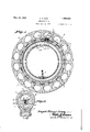
- Figure 1 is a vertical sectional elevation of a tire constructed in accordance with the invention, with the shoe or outer casing removed.
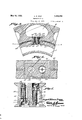
- Figure 2 is a vertical transverse sectional view therethrough of the tire.
- Figure 3 is an enlarged fragmentary vertical sectional elevation showing in detail the valve mechanism between the conduit and one of the air cells.
- Figure 4 is a sectional view on the line 4-4 of Figure 3, looking in the direction of the arrows.
- Figure 5 is an enlarged sectional view through the valve assembly shown in- F igure 3.
- the tire structure comprises an inner annular body A made from resilient material, such as rubber or a composition thereof, the cross sectional area of which conforms substantial- 1y to the cross sectional area of a shoe or outer casing B, either of the clincher or rim engaging type for the demounting of the tire from the rim 0 of a wheel, theshoe or outer casing being of any standard construction.
- the body A within the inner peripheral portion of the same, is formed with a circular continuous conduit 5 to which leads the valve stem 6, the latter being mounted in the body in the usual well known manner and through which is introduced air under pressure to said conduit.
- valve casings 9 Embedded in the body A concentrically with respect to the conduit 5 and encircling pairs of the valve casings 9 is areinforcing element 10, in this instance, of a pair of twisted wires which connect the entire series of valve casings 9 for the anchoring thereof and also for the reinforcement of the body A, as will be clearly apparent.
- each casing 9 comprises a pair of reversely set or operating valves 11 and 12, these being arranged in spaced air passages 13 and 1 1 respectively, tween each cell and the conduit and emand said valves have their stems 15 working bedded in the body, and a continuous reinin guides 16, while their heads are adapted forcement embedded in the body between the to engage valve seats 17 and 18 respectively. conduit and cells, and embracing the casings.
- the stem 15 of the valve 11 has about it a coiled tensioning spring 19 of a light tension to maintain the valve 11 engaged with the seat 17, the tension thereof being corresponding to approximately atmospheric pressure.
- the stem 15 of the valve 12 has engaged about the same a coiled tensioned spring 20, which is of a tension predetermined to withstand a determined pounds pressure of air to hold the valve engaged with its seat 18, the seats 17 and 18 for the valves being preferably removably threaded in the casing 9, while the latter at opposite ends confronting the conduit 5 and cells 7 are flush therewith and are provided with marginal rims 21 for the anchoring or seating of said casing in the body A of the tire.
- a coiled tensioned spring 20 which is of a tension predetermined to withstand a determined pounds pressure of air to hold the valve engaged with its seat 18, the seats 17 and 18 for the valves being preferably removably threaded in the casing 9, while the latter at opposite ends confronting the conduit 5 and cells 7 are flush therewith and are provided with marginal rims 21 for the anchoring or seating of said casing in the body A of the tire.
- the casing 9, as has been heretofore pointed out, includes therein a double valve with their heads in opposite directions so that valve 11 will confront the conduit 5 and the valve 12 confronting the cells 7 and the spring of the valve 12 will be calculated to sup- 7 port from the lowest to the highest pressure and will serve to allow the air to pass from the conduit 5 to the respective cells after exceeding the pressure in said conduit 5.
- this spring 20 calculated to a determined resistance, will prevent the escape of air from the remaining cells 7 and the conduit 5.
- a tire construction-of the character described comprising a resilient annular body having a continuous circular conduit and a plurality of spaced cells circumferentially and concentrically of the conduit, reversely.
Landscapes
- Engineering & Computer Science (AREA)
- Mechanical Engineering (AREA)
- Check Valves (AREA)
Description
ZSheets-Sheet 1 ATTORNEY/1 INVENTOR av W A. R. IR
PNEUMATIC TIRE Filed Dec. 19, 1 930 May 10, 1932. A. R. IRUZ 1,858,094
Patented May 10, 1932 UNITED STATES ANGEL RIVAS IRUZ, OF TORREON, MEXICO PNEUMATIC TIRE Application filed December 19, 1930. Serial No. 503,570.
formed with a main conduit for air and concentrically thereto a series of cells for air, these being in communication with the conduit for the purposes of maintaining the tire inflated when filled with air.
The primary object of the invention is the provision of a tire construction of th1s character, wherein the same will serve to prevent complete deflation should a puncture occur throughout any portion of the tread area of said tire, the tire in its make-up being novel in form and will sustain loads and having the required resiliency for service.
Another object of the invention is the provision of a tire of this character wherein it possesses the high degree of resiliency as 1n an ordinary pneumatic tire and which at the same time is so constructed that 1n event of a puncture, the area thereof so affected will not cause the deflation of the tire and thus in this manner keeping the tire in serviceable condition until its punctured area can be conveniently repaired.
A further object of the invention is the provision of a tire of this character which is slmple in construction, thoroughly eilicacious in its purpose, strong, durable and inexpensive to manufacture.
With these and other objects in view, the invention consists in the features of construction, combination and arrangement of parts, as will be hereinafter more fully described in detail, illustrated in the accompanying drawings which disclose the preferred embodiment of the invention, and pointed out in the claim hereunto appended.
In the accompanying drawings Figure 1 is a vertical sectional elevation of a tire constructed in accordance with the invention, with the shoe or outer casing removed.
Figure 2 is a vertical transverse sectional view therethrough of the tire.
Figure 3 is an enlarged fragmentary vertical sectional elevation showing in detail the valve mechanism between the conduit and one of the air cells.
Figure 4 is a sectional view on the line 4-4 of Figure 3, looking in the direction of the arrows.
Figure 5 is an enlarged sectional view through the valve assembly shown in- F igure 3.
Similar reference characters indicate corresponding parts throughout the several views in the drawings.
Referring to the drawings in detail, the tire structure comprises an inner annular body A made from resilient material, such as rubber or a composition thereof, the cross sectional area of which conforms substantial- 1y to the cross sectional area of a shoe or outer casing B, either of the clincher or rim engaging type for the demounting of the tire from the rim 0 of a wheel, theshoe or outer casing being of any standard construction.
The body A, within the inner peripheral portion of the same, is formed with a circular continuous conduit 5 to which leads the valve stem 6, the latter being mounted in the body in the usual well known manner and through which is introduced air under pressure to said conduit.
Within the body A concentrically with respect to the air conduit 5 is formed a plurality of equi-distantly spaced air chambers or cells 7, these being. of any desirable capacity or size and of any shape required to aflord maximum resiliency throughout the tread area 8, While embedded in the body A between the cells 7 and the conduit 5 and disposed radially in said body are valve casings 9 having valve mechanism in each of the same, as will be hereinafter-fully described.
Embedded in the body A concentrically with respect to the conduit 5 and encircling pairs of the valve casings 9 is areinforcing element 10, in this instance, of a pair of twisted wires which connect the entire series of valve casings 9 for the anchoring thereof and also for the reinforcement of the body A, as will be clearly apparent.
The valve mechanism in each casing 9 comprises a pair of reversely set or operating valves 11 and 12, these being arranged in spaced air passages 13 and 1 1 respectively, tween each cell and the conduit and emand said valves have their stems 15 working bedded in the body, and a continuous reinin guides 16, while their heads are adapted forcement embedded in the body between the to engage valve seats 17 and 18 respectively. conduit and cells, and embracing the casings.
The stem 15 of the valve 11 has about it a coiled tensioning spring 19 of a light tension to maintain the valve 11 engaged with the seat 17, the tension thereof being corresponding to approximately atmospheric pressure.
The stem 15 of the valve 12 has engaged about the same a coiled tensioned spring 20, which is of a tension predetermined to withstand a determined pounds pressure of air to hold the valve engaged with its seat 18, the seats 17 and 18 for the valves being preferably removably threaded in the casing 9, while the latter at opposite ends confronting the conduit 5 and cells 7 are flush therewith and are provided with marginal rims 21 for the anchoring or seating of said casing in the body A of the tire.
On inflating the tire, air under pressure is delivered to the conduit 5 through the stem 6 and the valves 12, and in this manner the chambers or cells 7 will be inflated simultaneously and likewise the conduit 5, all with a uniform pressure.
The casing 9, as has been heretofore pointed out, includes therein a double valve with their heads in opposite directions so that valve 11 will confront the conduit 5 and the valve 12 confronting the cells 7 and the spring of the valve 12 will be calculated to sup- 7 port from the lowest to the highest pressure and will serve to allow the air to pass from the conduit 5 to the respective cells after exceeding the pressure in said conduit 5. In event of the puncture of any one of the cells 7 this spring 20, calculated to a determined resistance, will prevent the escape of air from the remaining cells 7 and the conduit 5.
It will be apparent that when the tire is inflated, all of the chambers or cells 7, through the medium of the valve mechanism in the casing 9, are in free communication with the conduit 5, which latter forms a connecting conduit, thus rendering the tire practically as resilient as the ordinary pneumatic inner tube structure or tire. It will be apparent that the tire can be deflated like an ordinary pneumatic tire because when the pressure is reduced in the conduit 5, the valves 11 will open to bleed the chambers or cells 7 for the deflation or discharge of air therefrom.
What is claimed is A tire construction-of the character described, comprising a resilient annular body having a continuous circular conduit and a plurality of spaced cells circumferentially and concentrically of the conduit, reversely.
acting and varying tensioned valves controlling communication between each cell and the conduit, a casing containing the valves be- In testimony whereof I afliX my signature.
ANGEL RIVAS IRUZ.
Priority Applications (1)
| Application Number | Priority Date | Filing Date | Title |
|---|---|---|---|
| US50357030 US1858094A (en) | 1930-12-19 | 1930-12-19 | Pneumatic tire |
Applications Claiming Priority (1)
| Application Number | Priority Date | Filing Date | Title |
|---|---|---|---|
| US50357030 US1858094A (en) | 1930-12-19 | 1930-12-19 | Pneumatic tire |
Publications (1)
| Publication Number | Publication Date |
|---|---|
| US1858094A true US1858094A (en) | 1932-05-10 |
Family
ID=24002617
Family Applications (1)
| Application Number | Title | Priority Date | Filing Date |
|---|---|---|---|
| US50357030 Expired - Lifetime US1858094A (en) | 1930-12-19 | 1930-12-19 | Pneumatic tire |
Country Status (1)
| Country | Link |
|---|---|
| US (1) | US1858094A (en) |
Cited By (2)
| Publication number | Priority date | Publication date | Assignee | Title |
|---|---|---|---|---|
| US2841199A (en) * | 1956-08-28 | 1958-07-01 | Hans J Voelkel | Traction increasing assembly for vehicle tires |
| US2871904A (en) * | 1956-12-05 | 1959-02-03 | Chrysler Corp | Safety pneumatic tire |
-
1930
- 1930-12-19 US US50357030 patent/US1858094A/en not_active Expired - Lifetime
Cited By (2)
| Publication number | Priority date | Publication date | Assignee | Title |
|---|---|---|---|---|
| US2841199A (en) * | 1956-08-28 | 1958-07-01 | Hans J Voelkel | Traction increasing assembly for vehicle tires |
| US2871904A (en) * | 1956-12-05 | 1959-02-03 | Chrysler Corp | Safety pneumatic tire |
Similar Documents
| Publication | Publication Date | Title |
|---|---|---|
| US2608235A (en) | Valve structure for pneumatic tires having dual tubes | |
| GB1561701A (en) | Inner tube assembly for a pneumatic tyre | |
| US3064704A (en) | Pneumatic assembly for a vehicle wheel | |
| GB2024737A (en) | An inflatable interior support structure for a pneumatic tire | |
| US1858094A (en) | Pneumatic tire | |
| US2242788A (en) | Safety inner tube | |
| US2216368A (en) | Pneumatic tire | |
| US2070066A (en) | Ineumatic tube | |
| US3160191A (en) | Safety tire having an inner tire provided with a chafe and puncture resisting tread | |
| US2196814A (en) | Multiple chamber pneumatic tire | |
| US2027282A (en) | Tire and rim | |
| US1569844A (en) | Pneumatic or air-cushion tire | |
| US2871904A (en) | Safety pneumatic tire | |
| US1086947A (en) | Tire. | |
| US2168514A (en) | Safety tube | |
| US1460775A (en) | Tire structure | |
| US2345068A (en) | Vehicle tire | |
| US804088A (en) | Pneumatic tire. | |
| US446692A (en) | Vehicle-wheel | |
| US1373111A (en) | Resilient tubeless tire | |
| US2356508A (en) | Air tube for pneumatic tires | |
| US1384134A (en) | Pneumatic tire | |
| US1396170A (en) | Pneumatic tire | |
| US2469300A (en) | Tire | |
| US1334205A (en) | Cushion-tire |