US1858084A - Pressure regulating device for gases - Google Patents
Pressure regulating device for gases Download PDFInfo
- Publication number
- US1858084A US1858084A US315000A US31500028A US1858084A US 1858084 A US1858084 A US 1858084A US 315000 A US315000 A US 315000A US 31500028 A US31500028 A US 31500028A US 1858084 A US1858084 A US 1858084A
- Authority
- US
- United States
- Prior art keywords
- valve
- gas
- block
- chamber
- spring
- Prior art date
- Legal status (The legal status is an assumption and is not a legal conclusion. Google has not performed a legal analysis and makes no representation as to the accuracy of the status listed.)
- Expired - Lifetime
Links
- 239000007789 gas Substances 0.000 title description 42
- 230000001105 regulatory effect Effects 0.000 title description 13
- 230000002093 peripheral effect Effects 0.000 description 4
- 210000002445 nipple Anatomy 0.000 description 3
- 238000010276 construction Methods 0.000 description 2
- 230000001276 controlling effect Effects 0.000 description 2
- 239000000463 material Substances 0.000 description 2
- 238000005096 rolling process Methods 0.000 description 2
- 230000007547 defect Effects 0.000 description 1
- 230000000881 depressing effect Effects 0.000 description 1
- 230000000994 depressogenic effect Effects 0.000 description 1
- 230000000694 effects Effects 0.000 description 1
- 239000000835 fiber Substances 0.000 description 1
- 238000004519 manufacturing process Methods 0.000 description 1
- 239000007787 solid Substances 0.000 description 1
Images
Classifications
-
- G—PHYSICS
- G05—CONTROLLING; REGULATING
- G05D—SYSTEMS FOR CONTROLLING OR REGULATING NON-ELECTRIC VARIABLES
- G05D16/00—Control of fluid pressure
- G05D16/04—Control of fluid pressure without auxiliary power
- G05D16/06—Control of fluid pressure without auxiliary power the sensing element being a flexible membrane, yielding to pressure, e.g. diaphragm, bellows, capsule
- G05D16/063—Control of fluid pressure without auxiliary power the sensing element being a flexible membrane, yielding to pressure, e.g. diaphragm, bellows, capsule the sensing element being a membrane
- G05D16/0644—Control of fluid pressure without auxiliary power the sensing element being a flexible membrane, yielding to pressure, e.g. diaphragm, bellows, capsule the sensing element being a membrane the membrane acting directly on the obturator
- G05D16/0663—Control of fluid pressure without auxiliary power the sensing element being a flexible membrane, yielding to pressure, e.g. diaphragm, bellows, capsule the sensing element being a membrane the membrane acting directly on the obturator using a spring-loaded membrane with a spring-loaded slideable obturator
-
- Y—GENERAL TAGGING OF NEW TECHNOLOGICAL DEVELOPMENTS; GENERAL TAGGING OF CROSS-SECTIONAL TECHNOLOGIES SPANNING OVER SEVERAL SECTIONS OF THE IPC; TECHNICAL SUBJECTS COVERED BY FORMER USPC CROSS-REFERENCE ART COLLECTIONS [XRACs] AND DIGESTS
- Y10—TECHNICAL SUBJECTS COVERED BY FORMER USPC
- Y10T—TECHNICAL SUBJECTS COVERED BY FORMER US CLASSIFICATION
- Y10T137/00—Fluid handling
- Y10T137/7722—Line condition change responsive valves
- Y10T137/7781—With separate connected fluid reactor surface
- Y10T137/7793—With opening bias [e.g., pressure regulator]
- Y10T137/7794—With relief valve
-
- Y—GENERAL TAGGING OF NEW TECHNOLOGICAL DEVELOPMENTS; GENERAL TAGGING OF CROSS-SECTIONAL TECHNOLOGIES SPANNING OVER SEVERAL SECTIONS OF THE IPC; TECHNICAL SUBJECTS COVERED BY FORMER USPC CROSS-REFERENCE ART COLLECTIONS [XRACs] AND DIGESTS
- Y10—TECHNICAL SUBJECTS COVERED BY FORMER USPC
- Y10T—TECHNICAL SUBJECTS COVERED BY FORMER US CLASSIFICATION
- Y10T137/00—Fluid handling
- Y10T137/8593—Systems
- Y10T137/87917—Flow path with serial valves and/or closures
Definitions
- My invention relates to pressure regulating devicesv for gases.
- An object of the invention is to provide a device of this character which is so constructed that a more uni- 6 form reduced pressure will be maintained especially when the setting forpressure is ad- 1 justed and when the volume which is being withdrawn from the reduced pressure chamber is changed.
- An usual construction of the reducing valve employed in devices of this character is to make the valve'in one solid piece which in its movement has sidewise friction on the valve case and frequently a great dealof time must be spent during the manufacturing operation to determine whether any inaccuracy in the performance ofregulation is due to the sidewise friction or to misalignment of springs.
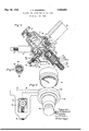
- Fig. 1 is a sectional elevational view of the device.
- Fig. 2 is a top plan view.
- Fig. 3 is a view in section on the line 3 3 of Fig. 1.
- I provide a support 10 which carries a yoke 12 within which the head 14 of a gas container containing gas under pressure is adapted to be secured by a screw 16.
- a support 10 which carries a yoke 12 within which the head 14 of a gas container containing gas under pressure is adapted to be secured by a screw 16.
- gas from the gas container passes through a passageway 18 to a member 20 constituting part of the support 10.
- the passageway 18 is provided with a pressure regulating device which includes an upwardly extended cap 22 screwed upon the upper dished side of an enlarged member 24 which in effect constitutes a portion of the support 10, this enlarged member being provided with a pro jectingtubular member 26, the lower portion of which is internally threaded to receive external threads formed on the upper portion ofa tubular member 28.
- the lower portion of the member 28 is reduced to form a shoulder 30 and below thisshoulder, it is externally screwthreaded to receive internal screwthreads formed in the upperportion of a hollow member 32.
- a perforation 34 in the member 20 extends down from the passageway 18, the material at the outer end of this perforation being formed as a valve seat 36. lVithin the tubular member 26. there is' a sliding block 38 carrying a fiber plug 40 at its upper end which constitutes a valve 75,
- the block 38 is held upwardly resiliently by a spring 42 interposed between the shoulder 30 and the lower end of the block 38.
- This block may be depressed to the desired extent 0 bymeans of a staplelike member 44, the lower ends of whose branches engage the upper end ofthe block 38 and whose upper end or cross member is engaged by the lower surface of a diaphragm 40 extending across the dished upper end of the member 24 so that a reduced pressure chamber 48 is formed below the diaphragm.
- the branches of the st-aplelike member 44 pass loosely through perforations in'the member 20 so that sufficient space is provided for the gas to pass upwardly through these perforations to the'chamber 48.
- a passage 54 in the member 24 connects the chamber 48 with a tubular member 55 carrying a lateral nipple 56 to which a rubber tube may be attached.
- the passageway through the member is controlled in suitable manner as by means of a needle valve 57 adapted to be opened to any desired extent.
- a passageway 58 in the member 24 connects the chamber 4:8 with a pressure gauge 60 by means of which the reduced pressure of gas in the chamber 48 is indicated. It is evident that this pressure may be varied by turning the screw 52 in one direction or the other to determine the position of the valve plug 40 with relation to the valve seat 36.
- I provide the following device.
- the block 38 is made considerably smaller in diameter than the inside diameter of the tubular member 26 and is surrounded by a sleeve 62 which is spaced slightly from the cylindrical surface of the block 38 and is also spaced slightly within the internal surface of the member 26.
- the sleeve 62 is provided with a plurality of perforations in which balls G l are placed.
- the material surrounding the perforations is swaged sufliciently to hold theballs in place but not to such an extent as to interfere with In the embodiment shown.
- This sleeve is preferably a floating sleeve spaced to allow some end play and is held in place by a shoulder 65 on the top of the block 238 while at the bottom the sleeve is prevented from dropping out by the upper turn of the spring 42.
- a slidable valve 66 which by means of a spring 68 is urgedupwardly into engagement with a seat 70 provided at the lower end of the tubular member 28.
- the spring (38 is backed up by a screw plug T2 adjustably mounted in the lower end of the member 32.
- valve 66 If the pressure of gas in the chamber 48 and the connection-s leading therefrom should tend to become excessive, the valve 66 by the pressure of the gas forced from its seat and some of the gas escapes from perforations Tl placed. in the member 32 just above the valve 36.
- the spacing of the sleeve 6'3 within the member 26 provides for passage of gas and enables the safety 'alve device to be attached in the manner just stated.
- the operation and advantages of my invcntion have to a large extent been indicated in connection with the pre eding description.
- the balls 64 provide a rolling engagement in stead of a sliding frictiimal engag ment of the blocl: 38 with the inner wall of the tabular member 26 whereby frictional binding of the block is prevented. Also the spacing of the sleeve 62 within such wall insures that the pressure of gas on the top and bottom of the block 38 carrying the valve 40 will always be equalized regardless of the settin The operation of the. device will be clearly understood by assuming that the needle valve 57 is partly opened so that gas is passing out of the nipple 56.
- valve 57 In case it is desired to increase the volume of gas which is being delivered by this nipple, the valve 57 is opened further. This tends to further reduce the pressure of gas in the chamber 48 so that the spring 50 depresses the diaphragm 46 which in turn opens the valve 40 further and permits more flow of gas. If new the valve 57 is brought back to its original position to decrease the flow of gas, the valve40 should also returnimmediately to its former position. If there is any binding or sticking of the slidable block-3S carrying the valve 4:0,it will not do this. The balls 64 insure against any such binding or sticking so that the valve 40 immediately assumes its proper position. Furthermore, there will be no binding of the block 38 when the screw 52 i turned to vary the reduced pressure of gas in the chamber'48.
- I claim 1 In a pressure regulating device for gases. the combination of a source of supply of gas under pressure, a dished member, a
- a connection for deliveringgas from said source to said chamber for deliveringgas from said source to said chamber.
- a valve seat in said connection a tubular member carried by said dished member, a slidable block in said tubular member, a plug carried by one end of said block for constituting a valve for engagement with said valve seat, a peripheral shoulder on said end of the block.
- a spring in said tubular member engaging the other end of said block and tending to hold said valve against said seat, a sleeve surrounding said block in spaced relation to the inner wall of said tubular member, said sleeve being held in position between said shoulder and said spring.
- a connection having a passageway leading from said chamber. and a device for controlling the volume of gas going through said passageway.
- a pressure regulating device for gases the combination of a source of supply of gas under pressure. a dished member. a diaphragm closing the open end of said dished member to form a chamber. a connection for delivering gas from said source to said chamber. a valve seat in said connection. a tubular member carried by said dished member. a slidable block in said tubular member. a plug carried by one end of said block for constituting a valve for engagement with said valve seat, a peripheral shoulder on said end of the block, a spring in said tubular member engaging the other end of said block and tending to hold said valve against said seat, an adjustable screw device for depressing said diaphragm to open said valve in opposition to the tension of said spring.
- a sleeve surrounding said block in spaced relation to the inner wall of said tubular member, said sleeve being held in position between said shoulder and said spring, balls carried by said sleeve engaging said inner wall, a valve opening member interposed between said diaphragm and said block, a connection having a passageway leading from said chamber, and a device for controlling the volume of gas going through said passageway.
- a pressure regulating device for gases the combination of a source of supply of gas under pressure, a chamber, a connection for passage of gas from said source to said chamber.
- a tubular member associated with said connection a sliding valve device in said tubular member having one of its ends adapted to control the passage of gas to said chamber, a peripheral shoulder on said end of the valve device.
- a spring in said tubular member engaging the other end of the valve device, a sleeve surrounding said valve device in spaced relation to the inner wall of said tubular member, said sleeve being held in position between said shoulder and said spring. and balls carried by said sleeve in engagement with said inner wall.
- a pressure regulating device for gases the combination of a source of supply of gas under pressure. a chamber. a connection for passage of gas from said source to said chamber. a tubular member associated with said connection. a sliding valve device in said tubular member having one of its ends adapted to control the. passage of gas to said chamber, a peripheral shoulder on said end of the valve device. a coiled spring in said tubular member having its inner end engaging the other end of the valve device, a sleeve surrounding said valve device in spaced relation to the inner wall of said tubular memher. the coil of said spring having a diameter greater than that of said valve device whereby said sleeve is held in position between said shoulder and said inner spring end. and balls carried by said sleeve in engagement with said inner wall.
- a pressure regulating device for cases. the combination of a fixed member having a passageway for gas. a tubular member ass v-iated with said fixed member, a sliding valve device in said tubular member adapted to control the passage of gas through said passagmvay. a spring in said tubular member tending to force said valve device into its closed position. a some surrounding said valve device in spaced relation to the in- In testimony whereof I hereunto affix my I signature.
Landscapes
- Physics & Mathematics (AREA)
- Fluid Mechanics (AREA)
- General Physics & Mathematics (AREA)
- Engineering & Computer Science (AREA)
- Automation & Control Theory (AREA)
- Control Of Fluid Pressure (AREA)
Description
y 10, 1932- J. A. HEIDBRINK ,858,084
PRESSURE REGULATING DEVICE FOR GASES Filed Oct. 25. 1928 my 1 so I n ven ton J'a g Heicibn'nk;
9 14 M m t torn eysl Patented May 10, 1932 JAY A. HEIDBBINK, OI MINNEAPOLIS, MINNESOTA PRESSURE REGULATING DEVICE FOR GASES Application filed October 25, 1928. Serial No. 315,000.
My invention relates to pressure regulating devicesv for gases. An object of the invention is to provide a device of this character which is so constructed that a more uni- 6 form reduced pressure will be maintained especially when the setting forpressure is ad- 1 justed and when the volume which is being withdrawn from the reduced pressure chamber is changed. An usual construction of the reducing valve employed in devices of this character is to make the valve'in one solid piece which in its movement has sidewise friction on the valve case and frequently a great dealof time must be spent during the manufacturing operation to determine whether any inaccuracy in the performance ofregulation is due to the sidewise friction or to misalignment of springs. These defects in performance show up more especially when the regulating device is used for the purpose ofdelivering very small volumes of gas under low reduced pressure, the initial tank pressure being very high. I accomplish the objects of my invention by providing a construction in which on account of rolling engagement of parts, there is no liability of frictional binding or sticking of the movable parts of the device; For illustrative purposes, I have shown my device applied in connection with a single source of gas supply, but it will be readily understood that the pressures of gases in connection with a plurality of sources of supply may also be regulated.
.The' full objects and advantages of my invention will appear in connection with the detailed description thereof, and the novel features of my inventive idea will be particularly pointed out in the claims.
In the accompanying drawings which illustrate a practical embodiment of my invent-ion,Fig. 1 is a sectional elevational view of the device. Fig. 2 is a top plan view. Fig. 3 is a view in section on the line 3 3 of Fig. 1.
As shown in the drawings, I provide a support 10 which carries a yoke 12 within which the head 14 of a gas container containing gas under pressure is adapted to be secured by a screw 16. As will be understood from Fig.
2, gas from the gas container passes through a passageway 18 to a member 20 constituting part of the support 10. As will be understood from Fig. l, the passageway 18 is provided with a pressure regulating device which includes an upwardly extended cap 22 screwed upon the upper dished side of an enlarged member 24 which in effect constitutes a portion of the support 10, this enlarged member being provided with a pro jectingtubular member 26, the lower portion of which is internally threaded to receive external threads formed on the upper portion ofa tubular member 28. The lower portion of the member 28 is reduced to form a shoulder 30 and below thisshoulder, it is externally screwthreaded to receive internal screwthreads formed in the upperportion of a hollow member 32. A perforation 34 in the member 20 extends down from the passageway 18, the material at the outer end of this perforation being formed as a valve seat 36. lVithin the tubular member 26. there is' a sliding block 38 carrying a fiber plug 40 at its upper end which constitutes a valve 75,
adapted to engage with the valve seat 36. The block 38 is held upwardly resiliently by a spring 42 interposed between the shoulder 30 and the lower end of the block 38. This block may be depressed to the desired extent 0 bymeans of a staplelike member 44, the lower ends of whose branches engage the upper end ofthe block 38 and whose upper end or cross member is engaged by the lower surface of a diaphragm 40 extending across the dished upper end of the member 24 so that a reduced pressure chamber 48 is formed below the diaphragm. The branches of the st-aplelike member 44pass loosely through perforations in'the member 20 so that sufficient space is provided for the gas to pass upwardly through these perforations to the'chamber 48. A. spring 50 which is stiiier than the spring 42 rests upon the upper surface of the diaphragm 46 while the tension of this spring is regulated by a'screw 52 threaded through the upper end of the extended cap 22 and engaging the upper end of the spring 50. Gas under the desired pressure may be delivered from the chamber 48 in any suitable manner.
, free turning of the balls.
As shown in Fig. 1, a passage 54 in the member 24 connects the chamber 48 with a tubular member 55 carrying a lateral nipple 56 to which a rubber tube may be attached. The passageway through the member is controlled in suitable manner as by means of a needle valve 57 adapted to be opened to any desired extent. A passageway 58 in the member 24 connects the chamber 4:8 with a pressure gauge 60 by means of which the reduced pressure of gas in the chamber 48 is indicated. It is evident that this pressure may be varied by turning the screw 52 in one direction or the other to determine the position of the valve plug 40 with relation to the valve seat 36. In order to prevent frictional binding or sticking of the slidable block 38 which carries the valve plug 40, I provide the following device. The block 38 is made considerably smaller in diameter than the inside diameter of the tubular member 26 and is surrounded by a sleeve 62 which is spaced slightly from the cylindrical surface of the block 38 and is also spaced slightly within the internal surface of the member 26. The sleeve 62 is provided with a plurality of perforations in which balls G l are placed. The material surrounding the perforations is swaged sufliciently to hold theballs in place but not to such an extent as to interfere with In the embodiment shown. there are two circular rows of balls with three equally spaced balls in each row. The size of the balls is such as to just nicely fill the inside and outside spaces of the sleeve 62. This sleeve is preferably a floating sleeve spaced to allow some end play and is held in place by a shoulder 65 on the top of the block 238 while at the bottom the sleeve is prevented from dropping out by the upper turn of the spring 42. ll'ithin the hollow member 32 previously referred to, there is a slidable valve 66 which by means of a spring 68 is urgedupwardly into engagement with a seat 70 provided at the lower end of the tubular member 28. The spring (38 is backed up by a screw plug T2 adjustably mounted in the lower end of the member 32. If the pressure of gas in the chamber 48 and the connection-s leading therefrom should tend to become excessive, the valve 66 by the pressure of the gas forced from its seat and some of the gas escapes from perforations Tl placed. in the member 32 just above the valve 36. The spacing of the sleeve 6'3 within the member 26 provides for passage of gas and enables the safety 'alve device to be attached in the manner just stated.
The operation and advantages of my invcntion have to a large extent been indicated in connection with the pre eding description. The balls 64 provide a rolling engagement in stead of a sliding frictiimal engag ment of the blocl: 38 with the inner wall of the tabular member 26 whereby frictional binding of the block is prevented. Also the spacing of the sleeve 62 within such wall insures that the pressure of gas on the top and bottom of the block 38 carrying the valve 40 will always be equalized regardless of the settin The operation of the. device will be clearly understood by assuming that the needle valve 57 is partly opened so that gas is passing out of the nipple 56. In case it is desired to increase the volume of gas which is being delivered by this nipple, the valve 57 is opened further. This tends to further reduce the pressure of gas in the chamber 48 so that the spring 50 depresses the diaphragm 46 which in turn opens the valve 40 further and permits more flow of gas. If new the valve 57 is brought back to its original position to decrease the flow of gas, the valve40 should also returnimmediately to its former position. If there is any binding or sticking of the slidable block-3S carrying the valve 4:0,it will not do this. The balls 64 insure against any such binding or sticking so that the valve 40 immediately assumes its proper position. Furthermore, there will be no binding of the block 38 when the screw 52 i turned to vary the reduced pressure of gas in the chamber'48.
I claim 1. In a pressure regulating device for gases. the combination of a source of supply of gas under pressure, a dished member, a
diaphragm closing the open end of said dished member to form a chamber. a connection for deliveringgas from said source to said chamber. a valve seat in said connection, a tubular member carried by said dished member, a slidable block in said tubular member, a plug carried by one end of said block for constituting a valve for engagement with said valve seat, a peripheral shoulder on said end of the block. a spring in said tubular member engaging the other end of said block and tending to hold said valve against said seat, a sleeve surrounding said block in spaced relation to the inner wall of said tubular member, said sleeve being held in position between said shoulder and said spring. balls carried by said sleeve engaging said inner wall, a valve opening member interposed between said diaphragm and said block. a connection having a passageway leading from said chamber. and a device for controlling the volume of gas going through said passageway.
2. In a pressure regulating device for gases. the combination of a source of supply of gas under pressure. a dished member. a diaphragm closing the open end of said dished member to form a chamber. a connection for delivering gas from said source to said chamber. a valve seat in said connection. a tubular member carried by said dished member. a slidable block in said tubular member. a plug carried by one end of said block for constituting a valve for engagement with said valve seat, a peripheral shoulder on said end of the block, a spring in said tubular member engaging the other end of said block and tending to hold said valve against said seat, an adjustable screw device for depressing said diaphragm to open said valve in opposition to the tension of said spring. a sleeve surrounding said block in spaced relation to the inner wall of said tubular member, said sleeve being held in position between said shoulder and said spring, balls carried by said sleeve engaging said inner wall, a valve opening member interposed between said diaphragm and said block, a connection having a passageway leading from said chamber, and a device for controlling the volume of gas going through said passageway.
3. In apressure regulating device for gases, the combination of a source of supply of gas under pressure, a chamber, a connection for passage of gas from said source to said chamber. a tubular member associated with said connection, a sliding valve device in said tubular member having one of its ends adapted to control the passage of gas to said chamber, a peripheral shoulder on said end of the valve device. a spring in said tubular member engaging the other end of the valve device, a sleeve surrounding said valve device in spaced relation to the inner wall of said tubular member, said sleeve being held in position between said shoulder and said spring. and balls carried by said sleeve in engagement with said inner wall.
4. In a pressure regulating device for gases. the combination of a source of supply of gas under pressure. a chamber. a connection for passage of gas from said source to said chamber. a tubular member associated with said connection. a sliding valve device in said tubular member having one of its ends adapted to control the. passage of gas to said chamber, a peripheral shoulder on said end of the valve device. a coiled spring in said tubular member having its inner end engaging the other end of the valve device, a sleeve surrounding said valve device in spaced relation to the inner wall of said tubular memher. the coil of said spring having a diameter greater than that of said valve device whereby said sleeve is held in position between said shoulder and said inner spring end. and balls carried by said sleeve in engagement with said inner wall.
5. In a pressure regulating device for cases. the combination of a fixed member having a passageway for gas. a tubular member ass v-iated with said fixed member, a sliding valve device in said tubular member adapted to control the passage of gas through said passagmvay. a spring in said tubular member tending to force said valve device into its closed position. a some surrounding said valve device in spaced relation to the in- In testimony whereof I hereunto affix my I signature.
JAY A. HEIDBBINK.
Priority Applications (1)
| Application Number | Priority Date | Filing Date | Title |
|---|---|---|---|
| US315000A US1858084A (en) | 1928-10-25 | 1928-10-25 | Pressure regulating device for gases |
Applications Claiming Priority (1)
| Application Number | Priority Date | Filing Date | Title |
|---|---|---|---|
| US315000A US1858084A (en) | 1928-10-25 | 1928-10-25 | Pressure regulating device for gases |
Publications (1)
| Publication Number | Publication Date |
|---|---|
| US1858084A true US1858084A (en) | 1932-05-10 |
Family
ID=23222428
Family Applications (1)
| Application Number | Title | Priority Date | Filing Date |
|---|---|---|---|
| US315000A Expired - Lifetime US1858084A (en) | 1928-10-25 | 1928-10-25 | Pressure regulating device for gases |
Country Status (1)
| Country | Link |
|---|---|
| US (1) | US1858084A (en) |
Cited By (3)
| Publication number | Priority date | Publication date | Assignee | Title |
|---|---|---|---|---|
| US2699800A (en) * | 1951-05-17 | 1955-01-18 | Crane Co | Fluid pressure regulator |
| US2878830A (en) * | 1956-02-27 | 1959-03-24 | Cash A W Co | Fluid control |
| US3269411A (en) * | 1964-02-12 | 1966-08-30 | Union Carbide Corp | Lecture bottle regulator |
-
1928
- 1928-10-25 US US315000A patent/US1858084A/en not_active Expired - Lifetime
Cited By (3)
| Publication number | Priority date | Publication date | Assignee | Title |
|---|---|---|---|---|
| US2699800A (en) * | 1951-05-17 | 1955-01-18 | Crane Co | Fluid pressure regulator |
| US2878830A (en) * | 1956-02-27 | 1959-03-24 | Cash A W Co | Fluid control |
| US3269411A (en) * | 1964-02-12 | 1966-08-30 | Union Carbide Corp | Lecture bottle regulator |
Similar Documents
| Publication | Publication Date | Title |
|---|---|---|
| US3095175A (en) | Gaseous fuel regulating device for liquefied gas lighters | |
| US2072629A (en) | Coupling device for carbonators | |
| US3228417A (en) | Pressure regulator with high pressure cut off | |
| US2793504A (en) | Portable apparatus utilizing pressurized gas fuel | |
| US3545471A (en) | Pressure regulator | |
| US2777456A (en) | Gas pressure regulators | |
| US1773726A (en) | Relief valve | |
| US3811400A (en) | Fluid operated alarm system | |
| US2343146A (en) | Valve | |
| US2804763A (en) | Metering valve for pocket lighters | |
| US2842146A (en) | Fluid pressure regulator and safety device | |
| US1858084A (en) | Pressure regulating device for gases | |
| US2278655A (en) | Automatic faucet | |
| US1920458A (en) | Control valve | |
| US1364972A (en) | Blow-torch | |
| US1412321A (en) | Appliance for delivering gaseous liquids | |
| US2652707A (en) | Mechanism for controlling emission of gas from lighters | |
| US2278728A (en) | Fluid pressure regulator | |
| US3820941A (en) | Lighter construction | |
| US2865592A (en) | Delayed action valve controlling apparatus | |
| US2074268A (en) | Relief valve and testing device | |
| GB1123278A (en) | A pressure indicator | |
| US3406000A (en) | Liquefied normally gaseous fuel control system for miniature burners | |
| US1888866A (en) | Control means | |
| US340696A (en) | Alexander caldwell |