US1858077A - Pipe cutting and beveling apparatus - Google Patents
Pipe cutting and beveling apparatus Download PDFInfo
- Publication number
- US1858077A US1858077A US493820A US49382030A US1858077A US 1858077 A US1858077 A US 1858077A US 493820 A US493820 A US 493820A US 49382030 A US49382030 A US 49382030A US 1858077 A US1858077 A US 1858077A
- Authority
- US
- United States
- Prior art keywords
- shaft
- torch
- pipe
- supporting
- cutting
- Prior art date
- Legal status (The legal status is an assumption and is not a legal conclusion. Google has not performed a legal analysis and makes no representation as to the accuracy of the status listed.)
- Expired - Lifetime
Links
Images


Classifications
-
- B—PERFORMING OPERATIONS; TRANSPORTING
- B23—MACHINE TOOLS; METAL-WORKING NOT OTHERWISE PROVIDED FOR
- B23K—SOLDERING OR UNSOLDERING; WELDING; CLADDING OR PLATING BY SOLDERING OR WELDING; CUTTING BY APPLYING HEAT LOCALLY, e.g. FLAME CUTTING; WORKING BY LASER BEAM
- B23K7/00—Cutting, scarfing, or desurfacing by applying flames
- B23K7/005—Machines, apparatus or equipment specially adapted for cutting curved workpieces
- B23K7/006—Machines, apparatus or equipment specially adapted for cutting curved workpieces for tubes
Definitions
- This invention relates to certain new and useful improvements in a pipe cutting and beveling apparatus, and more particularly to an improved machine for automatically preparing pipe intersections and joints for welding.
- 1t 1S necessary to cut a non-circular opening in the side of one pipe section and a correspondingly curved end portion on the other pipe section, these curved cuts varying in size and shape for each pipe diameter, and for each combination of pipe diameters when one of the pipes is smaller than the others.
- this is a slow and laborious procedure.
- it is necessary to bevel these out surfaces and to vary the bevel on one or both of the surfaces at different posi- U tions along the cut in order to provide a proper channel for the soldering metal used in the welding process.
- the present improved machine is adapted to automatically make continuous clean cuts in one or both 5 of the pipe sections and simultaneously cut torch.
- Means is provided adjacent one end of the shaft for supporting a pipe section with its longitudinal axis in line with the axis of the shaft, and at the other end of the shaft is means for supporting a pipe section at right angles to the shaft.
- Means is provided for rotating the shaft and simultaneously moving it longitudinally, and the torches are offset from the axis of the shaft so that they will follow curved non-circular 4.; paths as the shaft is moved.
- the torch at one end of the shaft is movably mounted with relation to the shaft so that it will follow the proper curved path to cut the opening in the side of one pipe section.
- the torch at u the other end of the shaft, which cuts the surface at the end of the branch pipe, is
- the principal object of this invention is to provide an improved pipe cutting and beveling apparatus such as briefly described hereinabove and disclosed more in detail in the specifications which follow;
- Another object is to provide impr'ov'ed means for varying the bevel of the'cut surface on one of the pipe sections/ Another object is to provide improved means for rotating the longitudinallymovable supporting shaft.
- Another object is to provide improved means for imparting the adjustable reciproeating movements to the supporting shaft.
- Another object is to provide improved means for automatically moving or swinging the torch-carriers with respect to the supporting shaft as the torches are revolved about the axis of the shaft.
- Another object is to provide an improved apparatus adapted to either separately or simultaneously cut both sections of pipe adapted for forming a cross connection.
- Another object is to provide improved means for cutting an opening in a pipe of any desired diameter up to and including the full diameter of the pipe.
- Another object is to provide improved means for adjusting the moving parts for operating upon pipes of diiferent diameters.
- Another object is to provide a machine of this type which is reversible so that the torches can be moved in either direction.
- Another object is to provide an improved apparatus for cutting and beveling pipe sections easily, quickly and entirely automatically, and in a single operation so that no additional beveling of the cut surfaces is necto the principles of this invention.
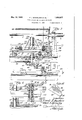
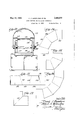
- Fig. 1 is a plan view of the assembled apparatus in operation for cutting pipe sections for a T joint.
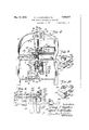
- FIG. 2 is a side elevation of the apparatus shown in Fig. 1.
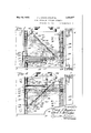
- Fig. 3 is a partial vertical section, on a larger-scale, taken substantially on the line 33'of Fig. 1.
- Fig. 4 is a transverse vertical section taken substantially on the line 4-4 of Fig. 3.
- - Fig. 5 is a detail vertical section, corresponding to a portion of Fig. 3, but with the parts adjusted for cutting pipe sections of the same diameter.
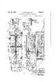
- Fig. 6 is an inverted plan view of a portion of-the apparatus, the View being taken substantially on the line 6-6 of Fig. 3.
- Fig. 7 is a partial horizontal section, the View being taken substantially on the line 77 of Fig. 3.
- Fig. 8 is a view similar to Fig. 7 showing the operating parts in a different position.
- Figs. 9 and '10 are perspective views of the roller-carriers which are mounted in the upper oscillating lever.
- Fig. 11 is a perspective view of the roller engaging bracket for imparting longitudinal movements to the operating shaft.
- Fig. 12 is an elevation of the torch-carrying mechanism shown at the left 1n F gs. 1 and 2, but in a different operative positlon.
- Fig. 13 is a plan view of the mechanism shown in Fig. 12, after the mechanism has been rotated through an angle of 90 from theposition shown in Fig. 12.
- Fig. 14 is a det'ail section, on a large scale
- Fig. 15 is a detail section taken substantially on the line 1515 of Fig. 13.
- Fig. 16 is a detail elevation of the torch mechanism shown at the right of Figs. 1 and 2.
- Fig. 17 is a detail view of a pair of assembled pipe sections ready for the welding operation.
- Fig. 18 is a detail section, taken substantially on the line 1818 of Fig. 17
- F 19 is a detailsection taken substantially on the line 19-19 of Fig. 18.
- Figs. 20 and 21 are views corresponding to Figs. 1 and 2 respectively, but showing the machine adapted for cutting sections for a pipe bend.
- Fig. 22 is an elevation of the adjustable directing plate, shown at the left of Figs. 20 and 21.
- F 23, 24, 25 and 26 illustrate different forms of pipe bends for which pipe sections can be cut by the apparatus shown in Figs. 20,21 and 22.
- F ig. 27 illustrates examples of cuts that would be made in a pipe section to form one of these angle bends.
- the apparatus will first be described as adjusted for cutting pipe sections for T joints or intersections, as shown in Figs. 1 to 19 inclusive, and the changes shown in Figs. 20 to 27 will then be described whereby the machine is adapted for cutting pipe sections for angle bends.
- the supporting frame in the form here shown, comprises corner posts or pillars 1 in the form of metallic angle beams, upper and lower supporting tables or partitions 2 and 3, and end yokes or arches 4 for supporting the main operating shaft 5 at a suitable height above the table 2.
- Shaft 5 is journaled in a pair of bearing blocks or journal boxes 6 each of which has a square or rectangular outer cross section and is supported by and guided for longitudinal movement between a set of four rollers 7 mounted on one of the arches 4.
- Collars 8 secured to the shaft 5 adjacent each end of each bearing block 6 compel the shaft 5 and bearings 6 to move longitudinally together, while permitting the shaft 5 to rotate within the nonrotating journal bearings.
- the torch mechanisms for cutting the pipe sections are carried by the respective projecting end portions of operating shaft 5, and the shaft 5 is rotated and reciprocated longitudinally for the purpose of imparting part of the necessary movements to the torch mechanisms. These desired movements to the shaft 5 will be hereinafter described, but we will first describe the cutting mechanisms mounted at the respective ends of the operating shaft.
- a small branch pipe 9 (shown at the right of Figs. 1 and 2) is to be welded into the side of the larger pipe 10 shown at the left of these figures. as 11 must be cut in the side of pipe 10 and the end of pipe 9 must be cut as indicated at 12. It will be obvious that the form or curvatures of these two cuts will be substantially identical. lVhen pipes of the same diameter are to be joined, the cuts will be of the form indicated in Figs. 16 to 19 inclusive.
- Mechanismmust also be provided for keeping the cutting torches substantially normal or perpendicular to the pipe surface at all times when a straight or unbeveled cut is to be made, or for imparting a constant or variable inclination to the torch with respect to the pipe surface in order to secure the desired bevel on the cut surface of the pipe.
- the pipe sections to be operated upon are supported upon a plurality of horses or pedestals 13, here shown as formed with forked upper arms 14 between which the pipe rests, the post 13 telescoping within a supporting pedestal 15 and being adjustable in height by means of a supporting pin 16 which is inserted in any one of a plurality of holes 17 in the post 13.
- the pipes should be supported so that the longitudinal axis of the pipe section lies in the same horizontal plane as the axis of shaft 5, and the posts 13 may be adjusted vertically in accordance with the diameter of the pipe that is being operated upon.
- the torch mechanism carried at the left-hand end of shaft 5 (Figs. 1 and 2) for the purpose of cutting the opening in the side of pipe 10 will now ,be described, referring more particularly to Figs. 1, 2, 12, 13, 14 and 15.
- the torch-carrier comprises a supporting arm 18 which is adjustable radially of shaft 5 through the head of a T-shaped socket member 19 removably secured on the end of shaft by any suitable means such as set screw 20. For the purpose of adjusting the arm 18 laterally of the shaft.
- a pinion 21 operated by a knob 22 meshes with a rack 23 formed on one side of arm 18, and the parts are In this case an opening such locked in adjusted position by means of the set screw 24.
- the torch-carrier is adjusted laterally in accordance with the diameter of the pipe to be cut, and the arm 18 may be calibrated as indicated at 25 to indicate the proper adjustment for any given size of pipe.
- a bracket 26 extends outwardly from one end portion of supporting arm 18, and four pairs of rollers 27 are supported by roller bearings 28 on stud shafts 29 mounted in the bracket i:
- An arcuate plate or carrier 30 is formed with inset runways 31 along its opposite edges which are engaged by the rollers 27 so that the plate 30 is firmly supported between the several sets of rollers but may be adjusted between these rollers along an arcuate or c1r-.
- a rigid guide tube 36 forming an extension of a flexible guide tube 35, is mounted in a supporting clamp pivoted at 33 in a bracket 32 mounted on and carried by the side of arm 18 as at.37.-
- a wire or flexible shaft 38 housed in the fiexlble guide tube 35 is connected with one end of a rigid rod 39 guided within tube 36.
- the torch 41 projects from the housing 42 which is supplied with the combustible fluids for the torch through flexible pipes or tubes 43.
- Housing 42 is mounted on arcuate plate 30 by means of screw bolts 44 which project through holes 45 formed in the arcuate plate and screw into cars 46 projecting from the opposite sides of housing 42.
- the torch is so mounted as to be normal to the surface of the pipe and thus cut a straight or unbeveled opening in the pipe. If the sides of this opening are to be beveled, the torch will be adjusted by shifting the position of the torch housing on the arcuate plate 30, that is by passing thebolts 44 through a pair of openings spaced toward the left in Fig. 12.
- FIG. 1 A supporting socket member 47 is secured to the end of shaft 5, as by means of set screw 18, and the supporting arm 49 is adjustable in socket 47 radially of shaft 5 and may be held in adjusted position by means of the set screw 50.
- Calibrated rack and pinion mechanism such as disclosed in connection with the first described form of torch carrier might be used for adjusting the arm 19 in the supporting socket 47, but such adjusting means is not as essential in this mechanism since the proper positioning of the torch 51 for cutting the end of shaft 9 can be more readily determined by inspection.
- a supporting yoke 52 comprising parallel side arms 53 extends from one end of supporting bar 49 and a torch carrying frame 54 has side arms 55 which are pivoted at 56 adjacent the ends of yoke arms 53.
- the torch 51 is fixedly mounted in the supporting frame 54 and is supplied with fuel through the flexible pipes 57.
- a flexible guide tube 58 forms a continuation of a rigid guide tube 58 secured in a supporting clamp 59 pivoted at 59 to a bracket arm 59 on one of the yoke arms 53.
- a flexible shaft or wire 60 housed in the flexible guide tube 58 is connected with the inner end of an operating rod 60 which reciprocates in the guide tube 58 and is pivotally attached at its outer end 60 to the pivoted frame 54.
- a suitable speed-changer and reversing mechanism 6i is interposed between shaft 65 which is driven by a motor 66 or any other suitable source of power, and a main drive shaft 67 whereby the speed of drive shaft 67 may be changed as desired. It will be apparent that in order for the cutting torches to remain over one portion of a pipe sufficiently long to properly perform the cutting operation, it will be necessary for the torches to revolve more slowly when cutting pipes of larger diameter than when cutting pipes of smaller diameter. The proper speed is obtained by means of the speed change gears 64.
- A. stationary anchoring plate 84 mounted at 85 on a part of the supporting frame. engages in a groove 86 formed in a hub 87 at one end of worm wheel 82, thus holding the worm wheel against lateral movements without interfering with the free ro tation of the worm wheel.
- a contractile spring 88 is anchored at one end 89 to a post 90 projecting upwardly from one of the supporting arches 4, the other end 91 of the spring being anchored to a bracket 92 projecting upwardly from the inner end of one of the bearing blocks 6.
- a plate or bracket 93 (see Fig. 11) is detachably mounted at its upper end, as at 94 on the bracket 92, or is secured to the slidable bearing 6 in any other suitable way, the lower portion of bracket 93 being formed with a horizontal flange 95 having a laterally extending roller engaging surface 96.
- Mechanism hereinafter described engages the surface 96 of bracket 93 to urge the bracket, andconsequently the shaft 5 toward the right (Figs.
- a secondworm 97 on vertical shaft 68 meshes with and drives a worm wheel 98 secured on one end of a horizontal shaft 99 journaled below, the supporting table 2 in bracket 100 and supporting yoke 101.
- a short vertical shaft 102 is journaled in the yoke 101 and table 2, and is driven from shaft 99 by means of the beveled gears 103.
- An auxiliary vertical shaft 102 is driven from shaft 102 by means of spur gearing 103 so proportioned that shaft 102 will rotate twice for each rotation of shaft 102.
- Mounted on the lower end of shaft 102 is a slotted crank arm 104.
- a roller-carrier 105 is slidably mount-- ed in the longitudinally slotted crank arm 104, and is provided with a laterally projecting internally threaded boss 106 in which meshes an adjusting screw 107 carried by a bearing 108 projecting from the outer end portion of crank arm 104.
- the adjusting screw 107 may be turned by means of the knurled head 109 so as to adjust the roller carrier 105 toward or from the axis of crank arm 104.
- a roller 110 mounted on a stud shaft 111 projecting downwardly from carrier 105 engages within a transverselyfextending slot 112 formed in a slide member or carriage 113 having oppositely extending arms 114 journaled in slide bearings 115 carried by the lower supporting table 3.
- the lower ends of the flexible guide tubes 35 and 58 have rigid extensions 35 and 58 anchored in a stationary bracket 116, and the lower ends of the wires 38 and are respectively connected with operating rods 38 and 60* which are attached at their outer ends to the slide frame or carriage 113.
- the slide frame 113 will be reciprocated longitudinally of the machine by means of the roller 110 engaging in the slot 112 of the slidable carriage, and corresponding longitudinal movements will be imparted to the two wires and 60, thus giving the desired movements to the arcnate torch carrier 30 and the pivoted torch carrying frame 54, already described.
- a crank arm 117 is secured to. the upper end of shaft 102 above table 2, this crank arm being longitudinally slotted so as to support and guide a second slidable roller-carrier 118 which is adjusted longitudinally of the crank arm 117 by an adjusting screw 119 in the same manner as the roller carrier first described.
- a sliding carriage 120 comprises a slotted bar member 121 extending longitudinally of the machine and connecting side frames or runners 122 which are" guided in slots 123 formed in transversely extending track members 124 supported on table 2.
- a shaft 125 extending longitudinally parallel to the slotted bar 121 is j ournaled in bearings 126 projecting from the slidable carriage 120, and carries spur gears 127 at its respective ends which mesh with racks 128 supported by the trackways 124.
- This rack and pinion gearing is to force the two ends of the slidable carriage 120 to move laterally in unison and prevent tilting or binding of the carriage in its guiding trackways 124.
- a roll-er 129 journaled, preferably by means of ball bearings, on a stud shaft 130 projecting upwardly from roller carrier 118, engages in a lower slot 131 formed in the longitudinally extending bar 121 of the carriage.
- the bar 121 is formed with a similar upper roller-receiving slot 132.
- slidable roller carriers 138 and 139 (shown in perspective in Figs. 9 and 10 respectively). Each of these carriers comprises a central body portion 140 engaged through one of the slots 13? in the lever 136, and upper and lower projecting slide flanges 141 engaging over the upper and lower surfaces respectively of the lever. From one of the side flanges 141 projects a hub 143 which is internally threaded at 144 to engage one of the threaded portions of an adjusting screw 145 which is journaled at its ends in the arms 146 projecting from the respective ends of lever 136, the screw 145 being rotated by a knurled head 147 at one end thereof. The respective end portions of screw 145 are oppositely threaded. at 148.
- a second roller 154 is supported at the lower side of carrier 139 and is adapted to engage in the upper slot or roller path'of the carriage 120.
- the stud shaft'13O for supporting roller 129 on carriage 118, and the roller supporting shaft 155 in carriage 139 are both hollow or tubular so that when positioned in alignment a pin 156 may be inserted through both of these tubular shafts so as to compel the crank-arm 117 and lever 136 to move in unison.
- roller carriers 118, 138 and 139 will be adjusted toward or from the "vertical axis of shafts 102 and 133 in accordance with the diameter of the pipes that are to be out.
- the roller carrier 118 will be adjusted closer to the axis of shaft 102 thanare the roller car riers 138 and 139, and the difference between the radiior revolution or oscillation of these roller carriers will varywith the relative differences in diameter between the two pipe sections.
- the crank'arm 117, roller carrier 118 and roller 129 will be continuously 'revolved through360 and will slide the carriage 120 laterally alternately in opposite directions in an obvious manner.
- roller carriers 118 and 139 will be adjusted so as to have the same radii of revolution, and the carriers will then be coupled together by the pin 156 asshown in Fig. 5 and the lever 136 will make a complete revolution of 360 along with the operating crank arm 117.
- bracket 93 It will be noted that it would be impractical to attempt to swing the lever 136through a complete arc of 180 in oppo site directions, as in the first described method of operation, since the roller 154 on carrier 139 in lever 136 would be on dead center in the slot 132 of the slidable frame 120 at the respective ends of the 180 arc of oscillation. This is avoided by continuously revolving the lever 136 and having the rollers 151 and 150 successively and alternately engage and push back the bracket 93, the movements thus imparted to the shaft 5 being the same as if one of the rollers, such as 151, were oscillated through an arc of 180.
- Fig. 23 illustrates a 90 or L pipe bend in which the two sections of pipe must be cut at angles of 45 as indicated at 157.
- This assembly comprises a supporting socket 164 which is secured to the end of shaft 5 by set screw 165 and carries a cross arm 166 adjustable in socket 164 by a rack andpinion mechanism 167 and locking set screw 168, as in the form of torch carrier first described.
- a bracket arm 169 projects laterally from one end of the supporting arm 166 and carries a pair of torches 170 which are adjusted to project their flames inwardly toward one another so as to form a single cut, each side of which is beveled inwardly as indicated at 171.
- Any suitable means can be provided for varying the inclination of the tore-hes in accordance with the bevel desired, and the torches are supplied with fuel in the usual manner through flexible tubes 172 connecting with mixing chamber 172 which supplies both burners;
- the torch assembly at the opposite end of shaft 5 is temporarily removed, and a means for giving the desired longitudinal movements to shaft 5 is substituted therefor.
- the bracket 93 will first be removed so that the mechanism previously described for moving shaft 5 longitudinally will no longer be operative.
- Adjustble clutch connections could be used in the drive shaft 99 whereby the mechanism driven from this shaft could be thrown into or out of operation as desired.
- a directing plate 17 3 is pivoted on a horizontal shaft 174 carried in the vertical arms 175 of a pedestal 176 which is removably mounted as at 177 on a shelf 178 supported at one end of the main frame of the machine.
- a sector plate 17 9 provided at one side of directing plate 173 is formed with an arcuate slot 180 through which projects a locking screw 181 mounted in one side 175 of the pedestal, whereby the inclination of plate 173 to the vertical may be adjusted as desired.
- An index pointer 182 mounted on the pedestal co-operates with a scale 188 on the sector plate to determine the angle of inclination of the directing plate 173.
- a removable socket member 18% is secured to shaft 5 by set screw 185 and carries a laterally adjustable supporting arm 186, here shown as secured in place by a thumb screw 187 and provided with an index scale 188 to indicate the lateral adjustment, although the forms of adjusting mechanism hereinabove described in connection with the torch carriers could be'used if desired.
- a bracket arm 189 secured at one end of supporting arm 186 carries a roller 190 which is adapted to follow a circular path on the surface of directing plate 173 and is continually held thereagainst by the spring 88.
- the shaft 5 will be rotated by means of worm wheel 82 in the usual-manner, and the burners or torches 170 will be revolved around the pipe sections, the inclination of the path of travel of these torches being determined by the angle at which directing plate 173 is adjusted, and the radius of the circular path traversed by roller 190.
- the radius of the path oftravel of roller 190 on directing plate 173 will be ad justed to correspond to the radius of the pipe section that is being cut.
- the angle of the cuts pro-- quizd in the pipe section will correspond to the angle at which directing plate 173 is set.
- the angle of the cuts produced by the torches may be varied for any given diameter of pipe by varying the inclination of directing plate 173.
- the plate 173 at a fixed inclination the angle of the cut produced in the pipe can be varied by changing the radius of the path of angular travel of roller 190. Either or both of these adjustments 'may be used singly for this purpose, if the adjusting scales are properly calibrated.
- the bracket arm 169 is shown broken away in Figs. and 21 since this arm can be made of greater length than shown in the drawings so as to project far enough along the pipe to cut off a pipe section of material length.
- a double torch mechanism be used with this apparatus.
- a single torch positioned to make either a beveled. or unbeveled out can be used.
- the machine can be used to cut a section of pipe at right-angles to the axis, or to bevel the end of a previously cut straight section of piping.
- a complete machine adapted to automatically cut pipe sections, suitable for welding, either for making T joints or intersections or for making angle bends.
- the machine' embodies a single mechanism for imparting continuous rotary motion to the shaft. and two alternative mechanisms for imparting longitudinal reciprocating movements to the operating shaft, one of these mechanisms being adapted to cause two complete reciprocations with simple harmonic motion for each rotation of the shaft when the machine is used for cutting pipe Sections for pipe intersections, and the other mechanism being used for impartin one complete reciprocation at varyin lin ear speeds to the shaft for each rotation thereof when the machine is used for cutting pipe sections for angle bends.
- the directing mechanism normally used for imparting simple harmonic reciprocation to the shaft being temporarily disconnected by removing bracket plate 93 or disconnecting the driving connection, as already described.
- this machine is entirely reversible and can be run in either direction. If any portion of a cut is not burned properly the machine can be reversed so as to return the torch over the imperfect portion of the cut, without disturbing any of the other adjustments.
- a pipe cutting apparatus a supporting frame, a main shaft journaled in the frame for both rotation and reciprocating movements longitudinally of the axis of the shaft, a cutting torch, means for supporting the torch in offset relation adjacent one end of the shaft, means for rotating the shaft, and means for imparting two complete cycles of reciprocations with simple harmonic motion to the shaft for each rotation thereof.
- a pipe cutting apparatus means for supporting a pipe-section, a cutting torch, means for supporting the torch, revolving same about the pipe section, and moving the torch longitudinally of the pipe as the torch is revolved, and means for automatically varying the the inclination of the torch with respect to the longitudinal axis of the pipe so'as to varythe bevel of the cut produced in the pipe.
- a pipe cutting apparatus means for supporting a pipe-section, a cutting torch, means for supporting and moving the torch so as to produce an endless cut in the pipe section, and means for automatically changing the inclination of the torch as it is moved to vary the bevel of the cut surface at different points in its length.
- a pipe cutting apparatus means for supporting a pipe-section, a cutting torch, means for supporting the torch, revolving the same about the pipe section, and'moving the torch longitudinally of the pipe as the torch is revolved, and means for automatically varying the inclination of the torch with respect to the longitudinal axis of the pipe as the torch is revolved, so as to produce a cut surface beveled at different angles at different circumferential portions of the pipe, said latter means comprising a swinging torch-supporting frame, a drive-shaft, a crank-arm on the drive shaft, a slotted slide frame, a roller adjustable longitudinally of the crank arm and engaging the slotted frame, and a flexible connection between the slide frame and the swingingtorchsupporting frame.
- a pipe cutting apparatus 'meansfor supporting a pipe-section, a cutting torch, means for supporting the torch, means for producing relative movement between the torch and pipe so that the torch will cut the pipe along a predetermined line, and means for automatically varying the inclination of the torch with respect to the pipe surface duringthis relative movement so as to vary the bevel at different points along the cut surface.
- an operating shaft means for rotating the shaft and imparting longitudinal movements thereto, a fork mounted at one end of the shaft, the arms of the fork extending parallel to the axis of the shaft but offset at one side thereof, a supporting frame pivoted between the arms of the fork, a cutting torch carried by 1 the frame and positioned to project the flame toward the axis of the shaft, and means for swinging the frame to change the inclination of the torch with relation to the axis of the shaft.
- an operating shaft means for rotating the shaft and im parting longitudinal movements thereto, a fork mounted at one end of the shaft, the arms of the fork extending parallel to the axis of the shaft but offset at one side thereof, a supporting frame pivoted between the arms of the fork, a cutting torch carried by the frame and positioned to project the flame toward the axis of the shaft, and means for swinging the frame as the shaft is rotated to vary the inclination of the torch with relation to the axis of the shaft.
- an operating shaft means for rotating the shaft and imparting longitudinal movements thereto, a fork mounted at one end of the shaft, the arms of the fork extending parallel to the axis of the shaft but offset at one side thereof, a supporting frame pivoted between the arms of the fork, a cutting torch carried by the frame and positioned to project the flame toward the axis of the shaft, and means mechanically operated from the shaft moving means for swinging the frame as the shaft is rotated to vary the inclination of the torch with relation to the axis of the shaft.
- an operating shaft means for rotating the shaft and imparting longitudinal movements thereto, means for supporting a pipe section so that its longitudinal axis corresponds with the axis of the shaft extended, a bracket carried by one end of the shaft so asto extend over and revolve about the pipe section, a cutting torch carried by the bracket so that the flame will project inwardly in a plane passing through the axis, and means for varying the inclination of the torch with relation to the axis as the shaft is rotated.
- an operating shaft means for rotating the shaft and imparting longitudinal movements thereto, means for supporting a pipe section so that its longitudinal axis corresponds with the axis of the shaft extended, a radially adj ustale bracket carried by the end of the shaft,
- said bracket comprising a fork, the arms of which project parallel to the axis and at one side of the pipe section so as to revolve therearound, a supporting frame pivoted between the arms of the fork, a cutting torch positioned on the supporting frame so that its flame will project inwardly in a plane passing through the axis, and means for swinging the supporting frame so asto vary the inclination of the torch with relation to the axis.
- a pipe cutting apparatus means for supporting a pipe section, a cutting torch, a rotary shaft, means for supporting the torch from one end portion of the shaft, meansfor rotating the shaft and means for simultaneously imparting longitudinal movements thereto so that the torch will follow a closed path to produce an endless cut in the pipe section, said means for rotating the shaft comprising a gear slidably keyed on the shaft, and means for rotating the gear.
- a pipe cutting apparatus means for supporting a pipe section, acutting torch, a rotary shaft, a movable support for the cutting torch mounted on one end portion of the shaft, means for rotating the shaft and simultaneously imparting longitudinal movements thereto so that the torch will fol low a closed path, and means for moving the torch support relative to the shaft comprising a rotary shaft, a crank arm on the shaft, a slotted slide-frame, a roller adjustable longitudinally of the crank arm and engaging the slotted frame, and a flexible connection between the slotted slide frame and the torch support.
- a pipe cutting apparatus means for supporting a pipe section, a cutting torch.
- a rotary shaft means for supporting the torch. from one end portion of the shaft, means for rotating; the shaft and means for simultaneously imparting longitudinal movements thereto so that the torch will follow a closed path to produce an endless cut in the pine section, said means for rotating the shaft comprising a gear slidablv keved on the shaft. and means for rotating the gear and sa d means for moving the shaft longitudina y comprising a spring mounted to continuallv urge the shaft in one direction, and rotary cam means acting to urge the shaft in the other direction in opposition to the spri g.
- a pipe cutting apparatus means for supporting: a pipe section, a cutting torch. a rotary shaft. means for supporting the torch from one end portion of the shaft. means for non-rotary member mounted to move longitudinally with the shaft and formed with a transversely extending surface, an oscillating member adapted to engage the surface, a rotary driving member, and means interposed between the two last mentioned members for converting rotary movement of one into oscillating movement of the other.
- a cutting torch In a pipe cutting apparatus, a cutting torch, a rotary shaft, means for rotatingthe shaft, means for supporting the torch in offset relation from one end portion of the shaft, and means for reciprocating the shaft longitudinally as it is rotated, said latter means comprising a spring mounted to continual- 1y urge the shaft in one direction, a non-rotary member mounted to move longitudinally with the shaft and formed with a transversely extending surface, an oscillating member adapted to engage the surface, a rotary driving member, means interposed between the two last mentioned members for converting rotary movement of one into oscillating movement; of the other, and means for adjusting the arc of oscillation of the oscillating member to determine the magnitude of the reciprocations of the shaft.
- a pipe cuttingapparatus means for supporting a pipe section, a cutting torch, a rotary shaft, means for supporting the torch from one end portion of the shaft, means for rotating the shaft, and means for simultaneously imparting longitudinal movements to the shaft so that the torch will follow a closed path to produce an endless cut in the pipe section
- said last mentioned means comprising a non-rotary bracket member connected with the shaft to move longitudinally therewith and having a roller engaging surface extending atright angles to the path of movement of the member, a spring which tends to urge the member and shaft in one direction, a pivoted lever, a roller adjustable on the lever toward or from the fulcrum thereof, said roller engaging the surface on the bracket member to move the member in opposition to the spring, and means for oscillating the lever.
- a rotary shaft means for supporting the torch from one end portion of the shaft, means for rotating the shaft, and means for simultaneously impartin g longitudinal movements to'the shaft so that the torch will follow a closed path to produce an endless cut in the pipe section
- said last mentioned means comprising a non-rotary bracket member connected with the shaft to move longitudinally therewith and having a roller engaging surface extending at right angles to the path of movement of the member, a spring which tends to urge the member and shaft in one direction, a pivoted lever, a roller adjustable on the lever toward or from the fulcrum thereof, said roller engaging the surface on the bracket member to move the member in opposition to the spring, and means for oscillating the lever comprising a slotted slide member, a roller on the lever engaging the slotted slide member, a rotary drive shaft, a crank-arm on the drive shaft, and a roller adjustable on the crank-arm and engaging the slotted slide member.
- a pipe cutting apparatus means for supporting a pipe section, a cutting torch, a rotary shaft, means for supporting the torch from one end portion of the shaft, means for rotating the shaft, and means for simultaneously imparting longitudinal movements to the shaft so that the torch will follow a closed path to produce an endlesscut in the pipe section
- said last mentioned means comprising a non-rotary bracket member connected with the shaft to move longitudinally therewith and having a roller engaging surface extending at right angles to the path of movement of the member, a spring which tends to urge the member and shaft in one direction, an intermediately pivoted lever, a pair of rollers one being adj ustably mounted on each arm of the lever toward or from the fulcrum thereof, said rollers being adapted to engage the surface on the bracket member to move the member in opposition to the spring, and means for rotating the lever.
- a pipe cutting apparatus means for supporting a pipe section, a cutting torch, a rotary shaft, means for supporting the torch from one end portion of the shaft, means for rotating the shaft, and means for simultaneously imparting longitudinal movements to the shaft so that the torch will follow a closed path to produce an endless cut in the pipe section
- said last mentioned means comprising a non-rotary bracket member connected with the shaft to move longitudinally therewith and having a roller engaging surface extending at right angles to the path of movement of the member, a spring which tends to urge the member and shaft in one direction, an intermediately pivoted lever, a pair of rollers one being adjustably mounted on each arm of the lever toward or from the fulcrum thereof, said rollers being adapted to engage the surface on the bracket memher to move the member in opposition to the spring and means for either oscillating the lever through an angle of less than 180 so that one of the rollers continuously engages the bracket. or rotating the lever through 360 so that both rollers successively engage the bracket.
- said last mentioned means comprising a non-rotary bracket member connected with the shaft to move longitudinally therewith and having a roller engaging surface extending at right angles to the path of movementof the member, a spring which tends to urge the member and shaft in one direction.
- an intermediately pivoted lever a pair of rollers one being adjustably mounted on each arm of the lever toward or from the fulcrum thereof, said rollers being adapted to engage the surface on the bracket member to move the member in opposition to the spring, and means for either oscillating the lever through an angle of less than 180 so that one of the rollers continuously engages the bracket, or rotating the lever hrough 360 so that both rollers successively engage the bracket, said latter means comprising a slotted slide member, a drive shaft mounted coaxially with the lever, a crank-arm on the drive shaft, a roller on the lever and a roller on the crank-arm both rollers engaging the slotted slide, the i roller on the crank-arm being adjustable longitudinally of the crank-arm so that it may have the same or a less radius of revolution than the last mentioned roller on the lever whereby the lever is rotated or oscillated respectively.
- a rotary shaft In a pipe cuttlng apparatus, a rotary shaft, means for supporting a p pe section adjacent one end of the shaft ith the gitudinal movements thereto whereby each 7 torch will follow an endless non-circular path, and means for moving each of the torch-supporting frames relative to the shaft to vary the inclination of each torch with respect to the axis of the shaft as the shaft rotates.
- a rotary shaft means for supporting a pipe section adjacent one end of the shaftwith the longitudinal axis of the pipe section in line with the axis of the shaft, means for supporting a pipe section adjacent the other end of the shaft with its axis at right angles to the axis of the shaft, a pair of cutting torches, means for supporting each torch on one end portion of the shaft, each torch-support comprising a movable frame for swinging the torch relative to the shaft, means for rotating the shaft and simultaneously imparting longitudinal movements thereto whereby each torch will follow an endless non-circular path, and
- each of the torch-supporting frames means for moving each of the torch-supporting frames relative to the shaft to vary the inclination of each torch with respect to the axis of the shaft as the shaft rotates, said means comprising a rotary drive shaft, a crank-arm on this shaft, a slotted slideframe, a roller adjustable longitudinally of the crank-arm and engaging the slotted frame, and flexible connections extending from the slide-frame to each of the movable torch supporting frames.
- a rotary shaft means for supporting a pipe section adjacent one end of the shaft with the longitudinal axis of the pipe section in line with the axis of the shaft, means for supporting a pipe section adjacent the other end of the shaft with its axis at right angles to the axis 3 of the shaft, a pair of cutting torches, means for supporting each torch on one end portion of the shaft, each torch-support comprising a movable frame for swinging the torch rel ative to the shaft and means for rotating the shaft, imparting longitudinal movements thereto and moving each torch-supporting frame relative to the shaft, said means comprising a drive-shaft, change-speed means for rotating the drive shaft, a gear nonrotatably but slidably keyed on the first mentioned shaft, means for rotating said gear from the drive shaft, a driven shaft positioned at right angles to the drive shaft and first mentioned shaft; gear connections for rotating the driven shaft from the drive shaft, a crank arm on the driven shaft, a second drive shaft, gear connections for rotating the second
- a rotary shaft means for supporting a pipe section adjacent one end of the shaft with the longitudinal axis of the pipe section in line with the axis of the shaft, means for supporting a pipe section adjacent the other end of the shaft with its axis at right angles to the axis of the shaft, a pair of cutting torches, means for supporting each torch on one end portion of the shaft, each torch-support comprising a movable frame for swinging the torch relative to the shaft, and means for rotating the shaft, imparting longitudinal movements thereto and moving each torch-supporting frame relative to the shaft, said means comprising a drive-shaft, change-speed means for rotating the drive shaft, a gear nonrotatably but slidably keyed on the first mentioned shaft, means for rotating said gear from the drive shaft, a driven shaft positioned at right angles to the drive shaft and first mentioned shaft, gear connections for rotating the driven shaft from the drive shaft, a crank arm on the driven shaft, a second driven shaft, gear connections for rotating the second driven shaft
- a pipe cutting apparatus In a pipe cutting apparatus, a supporting frame, a main shaft journaled in the frame for both rotary motion and bodily reciprocating movements longitudinally of the axis of the shaft, a cutting torch mechanism carried in offset relation at one end of the shaft, means for rotating the shaft, two separate mechanisms for reciprocating the shaft, one with a simple harmonic motion for cutting pipes for pipe intersections, and one for cutting pipes for angle bends, and means for alternatively connectingsaid reciprocating mechanisms with the main shaft.
- a pipe cutting apparatus In a pipe cutting apparatus, a supporting frame, a main shaft journalled in the frame for both rotary motion and bodily reciprocating movements longitndinallv of the axis of the shaft, cutting torch mechanisms carried in oflset relation at the respective ends of the shaft, means for rotating theshaft. means detachably connected with the shaft for reciprocating the same with simple harmonic motion whereby the cutting torches to the shaft whereby a to .the ooiosite end of the. shift will cut 31 3e sections for an angle bend.
- a pipe cutting apparatus a supporting frame, a main shaft journalled in the frame for bothrotar motion and bodily re- -'ciproc ating movements longitudinally of the 'axis of the shaft, cutting torch mechan carried in offset relation atthe respectix of the shaft.
- a substitute torch mechanism which is attachable at one end ofthe shaft for in in a pipe section with opposi king a out bevelled edges for use in anangic bend, and a mechanis nwhicn lsadapted to be substituted for L l 1 .L LhG torch mechanism at tee 0L shaft for nnparting rcciprocat nor ennl of the motions of variable amplitude to the shaft ion the subst tute torch mechanism 1s installed.
- a pipe cutting apparatus In a pipe cutting apparatus, a supporting frame, a main shaft journaled in the frame for both rotation and reciprocating movements longitud nally of the axis of the shaft, a cutting torch, means for supporting the torch in offset relation adjacent one end of the shaft, means for rotating the shaft in either direction, and means for reciprocating the shaft with simple harmonic motion as the shaft is rotated.
- a pipe cutting apparatus means for supporting a pipe section, a cutting torch, a rotary shaft, a movable support for the cutting torch mounted on one end portionof the shaft, means for rotating the shaft and simultaneously imparting longitudinal movements thereto so that the torch will follow a closed path, and means for moving the torch support relative to the shaft comprising a rotary shaft, means for rotating this latter shaft twice for each rotation of the first mentioned shaft, a crank arm on the second shaft,
- an operating shaft In pipe cutting apparatus, an operating shaft, a laterally projecting torch-carrier on the shaft, an arcuate slide, guides for the slide on the carrier, a cutting torch mounted on the slide, means for rotating the shaft and imparting longitudinal movements thereto, a rigid guidemember ,pivotally mounted on the carrier, a flexible guide-tube forming an extension of the rigid guide, a flexible shaft longitudinall movable through the flexible tube, a rigid operating rod guided in the rigid member and attached at its inner end to the flexible shaft, the other end of the operating rod being pivotally attached to the arcuate slide, and means for reciprocating the flexible shaft.
- an operating shaft In pipe cutting apparatus, an operating shaft, a laterally projecting torch-carrier on the shaft, an arcuate slide, guides for the slide on the carrier, a cutting torch mounted on the slide, means forrotating the shaft and imparting longitudinal movements thereto, a rigid guide-member pivotally mounted on the carrier, a flexible guide-tube forming an extension of the rigid guide, a flexible shaft longitudinally movable through the flexible tube, arigid operating rod guided inthe rigid-member and attached at its inner end to the flexible shaft, the other end of the operating rod being pivotally attached tothe arcuate slide, and means for reciprocating the flexible shaft twice in each direction for each rotation of the operating shaft.
Landscapes
- Engineering & Computer Science (AREA)
- Mechanical Engineering (AREA)
- Arc Welding In General (AREA)
Description
May 10, 1932. F. J. DOUGLASS ET AL PIPE, CUTTING AND BEVELING APPARATUS Filed Nov. 6. 1930 8 Sheets-Sheet l wm kw MMWN 8 She ets-Sheet 2 F. J. DOUGLASS ET AL PIPE CUTTING AND BEVELING APPARATUS May 10, 1932.
Imfen mas 7212 7225} J .3011 088 er 1% 021/ owgyg May 10, 1932. F. J. DOUGLASS ET AL PIPE CUTTING AND BEVELING APPARATUS Filed Nov. 6, 1930 8 Sheets-Sheet 3 Inlf arm I egg/ass if ma s;
Tran a A/firf @alvv-m F. .1. DOUGLASS ET AL 1,353,077
PIPE CUTTING AND BEVELING APPARATUS Filed Nov, 6, 1930 8 Sheets-Sheet 4 Inwfen 0 rs ?;MQSS
orngys.
May 10, 1932.
May 10, 1932. F. J. DOUGLASS ET AL PIPE CUTTING AND BEVELING APPARATUS 8 Sheets-Sheet 5 Filed Nov. 6, 1930 2%; .ih? m Imfentons l r m mm NM Fan/f ,[Z?l Q }Z eff/5% awe orne May 10, 1932.
F. J. DQUGLASS ET AL PIPE CUTTING AND BEVELING APPARATUS Filed Nov. 6. 1950 8 Sheets-Sheet 6 ITufen an J2 Tr m? lly/Q51? A/fierfd May 10, 1932. F. J. DOUGLASS ET AL PIPE CUTTING AND BEVELING APPARATUS Filed Nov. 6. 1930 8 Sheets-Sheet 7 y 10, 1932- F. J. DOUGLASS ET AL 1,858,077
PIPE CUTTING AND BEVELING APPARATUS Filed Nov. 6, 1930 8 Sheets-Sheet 8 ImFEn EE Tw2% [3;yizw
a i l/5872157 0 21/[5 @M 3&5.
Patented May 10, 1932 UNITED STA ES PATENT OFFICE FRANK J. DOUGLAS$ AND ALBERT S. MCCAWLEY, OF CHICAGO, ILLINOIS, ASSIGNOBS TO DOUGLASS BROTHERS COMIPANY, OF CHICAGO, ILLINOIS, A CORPORATION OF ILLINOIS PIPE CUTTING AND BEVELING APPARATUS Application filed November 6, 1939. Serial No. 493,820.
This invention relates to certain new and useful improvements in a pipe cutting and beveling apparatus, and more particularly to an improved machine for automatically preparing pipe intersections and joints for welding.
In making pipe tees or crosses or similar 3o1nts or connections, 1t 1S necessary to cut a non-circular opening in the side of one pipe section and a correspondingly curved end portion on the other pipe section, these curved cuts varying in size and shape for each pipe diameter, and for each combination of pipe diameters when one of the pipes is smaller than the others. When performed by hand this is a slow and laborious procedure. Furthermore, it is necessary to bevel these out surfaces and to vary the bevel on one or both of the surfaces at different posi- U tions along the cut in order to provide a proper channel for the soldering metal used in the welding process. The present improved machine is adapted to automatically make continuous clean cuts in one or both 5 of the pipe sections and simultaneously cut torch. Means is provided adjacent one end of the shaft for supporting a pipe section with its longitudinal axis in line with the axis of the shaft, and at the other end of the shaft is means for supporting a pipe section at right angles to the shaft. Means is provided for rotating the shaft and simultaneously moving it longitudinally, and the torches are offset from the axis of the shaft so that they will follow curved non-circular 4.; paths as the shaft is moved. The torch at one end of the shaft is movably mounted with relation to the shaft so that it will follow the proper curved path to cut the opening in the side of one pipe section. The torch at u the other end of the shaft, which cuts the surface at the end of the branch pipe, is
mounted in a swinging frame so that the effective inclination of the torch or cutting Jet with relation to the axis of the shaft and pipe can be varied as the torch is revolved so that the proper variable bevel will be formed on the end of the branch pipe. By substituting a different type of torch at thela-st mentioned end of the shaft, and substituting a directing plate for the torch at the firstmentioned end of the shaft the machine is adapted for cutting and beveling pipe sections for making angular or L bends. .Improved driving means is provided, as hereinafter set forth, for imparting the necessary movements to the supporting shaft and the torch-carriers.
The machine disclosed and claimed in this present application is an improvement on the apparatus disclosed and claimed in the copending application of Frank J. Douglass, Serial No. 4:78, 269, filed August 27, 1930, in which prior application many of the features herein disclosed are broadly. claimed.
.The principal object of this invention is to provide an improved pipe cutting and beveling apparatus such as briefly described hereinabove and disclosed more in detail in the specifications which follow;
Another object is to provide impr'ov'ed means for varying the bevel of the'cut surface on one of the pipe sections/ Another object is to provide improved means for rotating the longitudinallymovable supporting shaft. I
Another object is to provide improved means for imparting the adjustable reciproeating movements to the supporting shaft.
Another object is to provide improved means for automatically moving or swinging the torch-carriers with respect to the supporting shaft as the torches are revolved about the axis of the shaft.
Another object is to provide an improved apparatus adapted to either separately or simultaneously cut both sections of pipe adapted for forming a cross connection.
Another object is to provide improved means for cutting an opening in a pipe of any desired diameter up to and including the full diameter of the pipe.
Another object is to provide improved means for adjusting the moving parts for operating upon pipes of diiferent diameters.
Another object is to provide an improved machine adapted for alternately cutting and beveling pipe sections for T joints or intersections, for angular or L bends, or for cutting and beveling straight sections of pipe. Another object is provide a machine adapted to operate and direct several diiferent alternative types of cutting torches for cutting pipe sections for various purposes.
Another object is to provide a machine of this type which is reversible so that the torches can be moved in either direction.
Another object is to provide an improved apparatus for cutting and beveling pipe sections easily, quickly and entirely automatically, and in a single operation so that no additional beveling of the cut surfaces is necto the principles of this invention.
In the accompanying drawings:
Fig. 1 is a plan view of the assembled apparatus in operation for cutting pipe sections for a T joint.
'Fig. 2 is a side elevation of the apparatus shown in Fig. 1.
Fig. 3: is a partial vertical section, on a larger-scale, taken substantially on the line 33'of Fig. 1.
Fig. 4 is a transverse vertical section taken substantially on the line 4-4 of Fig. 3.
- Fig. 5 is a detail vertical section, corresponding to a portion of Fig. 3, but with the parts adjusted for cutting pipe sections of the same diameter.
Fig. 6 is an inverted plan view of a portion of-the apparatus, the View being taken substantially on the line 6-6 of Fig. 3.
Fig. 7 is a partial horizontal section, the View being taken substantially on the line 77 of Fig. 3.
Fig. 8 is a view similar to Fig. 7 showing the operating parts in a different position.
Figs. 9 and '10 are perspective views of the roller-carriers which are mounted in the upper oscillating lever.
Fig. 11 is a perspective view of the roller engaging bracket for imparting longitudinal movements to the operating shaft.
Fig. 12 is an elevation of the torch-carrying mechanism shown at the left 1n F gs. 1 and 2, but in a different operative positlon.
Fig. 13 is a plan view of the mechanism shown in Fig. 12, after the mechanism has been rotated through an angle of 90 from theposition shown in Fig. 12.
Fig. 14 is a det'ail section, on a large scale,
simultaneously taken substantially on the line 14-14 of Fig. 13.
Fig. 15 is a detail section taken substantially on the line 1515 of Fig. 13.
. Fig. 16 is a detail elevation of the torch mechanism shown at the right of Figs. 1 and 2.
Fig. 17 is a detail view of a pair of assembled pipe sections ready for the welding operation.
Fig. 18 is a detail section, taken substantially on the line 1818 of Fig. 17
Figs. 20 and 21 are views corresponding to Figs. 1 and 2 respectively, but showing the machine adapted for cutting sections for a pipe bend.
Fig. 22 is an elevation of the adjustable directing plate, shown at the left of Figs. 20 and 21.
F ig. 27 illustrates examples of cuts that would be made in a pipe section to form one of these angle bends.
The apparatus will first be described as adjusted for cutting pipe sections for T joints or intersections, as shown in Figs. 1 to 19 inclusive, and the changes shown in Figs. 20 to 27 will then be described whereby the machine is adapted for cutting pipe sections for angle bends.
The supporting frame, in the form here shown, comprises corner posts or pillars 1 in the form of metallic angle beams, upper and lower supporting tables or partitions 2 and 3, and end yokes or arches 4 for supporting the main operating shaft 5 at a suitable height above the table 2. Shaft 5 is journaled in a pair of bearing blocks or journal boxes 6 each of which has a square or rectangular outer cross section and is supported by and guided for longitudinal movement between a set of four rollers 7 mounted on one of the arches 4. Collars 8 secured to the shaft 5 adjacent each end of each bearing block 6 compel the shaft 5 and bearings 6 to move longitudinally together, while permitting the shaft 5 to rotate within the nonrotating journal bearings. The torch mechanisms for cutting the pipe sections are carried by the respective projecting end portions of operating shaft 5, and the shaft 5 is rotated and reciprocated longitudinally for the purpose of imparting part of the necessary movements to the torch mechanisms. these desired movements to the shaft 5 will be hereinafter described, but we will first describe the cutting mechanisms mounted at the respective ends of the operating shaft.
lhe mechanism for giving J.
It will be apparent that when a welded T iii;
joint is to be formed, an opening must be cut in the side of one pipe section, and the end of another pipe section must be cut on a corresponding curve so as to fit this opening. In the example shown in Figs. 1 and 2, a small branch pipe 9 (shown at the right of Figs. 1 and 2) is to be welded into the side of the larger pipe 10 shown at the left of these figures. as 11 must be cut in the side of pipe 10 and the end of pipe 9 must be cut as indicated at 12. It will be obvious that the form or curvatures of these two cuts will be substantially identical. lVhen pipes of the same diameter are to be joined, the cuts will be of the form indicated in Figs. 16 to 19 inclusive. It will now be apparent that the paths that must be followed by the cutting torches will vary in accordance with the sizes of the pipes that are to be out, and also in accordance with the relative sizes or diameters of the two pipe sections that are to be joined together. Mechanismmust also be provided for keeping the cutting torches substantially normal or perpendicular to the pipe surface at all times when a straight or unbeveled cut is to be made, or for imparting a constant or variable inclination to the torch with respect to the pipe surface in order to secure the desired bevel on the cut surface of the pipe.
The pipe sections to be operated upon are supported upon a plurality of horses or pedestals 13, here shown as formed with forked upper arms 14 between which the pipe rests, the post 13 telescoping within a supporting pedestal 15 and being adjustable in height by means of a supporting pin 16 which is inserted in any one of a plurality of holes 17 in the post 13. The pipes should be supported so that the longitudinal axis of the pipe section lies in the same horizontal plane as the axis of shaft 5, and the posts 13 may be adjusted vertically in accordance with the diameter of the pipe that is being operated upon. It will be noted that the pipe 10 must be supported so that its axis extends at right angles to the axis of shaft 5, whereas the branch pipe section 9 is supported so that its longitudinal axis coincides with that of the axis of shaft 5, and the supporting horses 13 will be positioned accordingly. The torch mechanism carried at the left-hand end of shaft 5 (Figs. 1 and 2) for the purpose of cutting the opening in the side of pipe 10 will now ,be described, referring more particularly to Figs. 1, 2, 12, 13, 14 and 15. The torch-carrier comprises a supporting arm 18 which is adjustable radially of shaft 5 through the head of a T-shaped socket member 19 removably secured on the end of shaft by any suitable means such as set screw 20. For the purpose of adjusting the arm 18 laterally of the shaft. a pinion 21 operated by a knob 22 meshes with a rack 23 formed on one side of arm 18, and the parts are In this case an opening such locked in adjusted position by means of the set screw 24. The torch-carrier is adjusted laterally in accordance with the diameter of the pipe to be cut, and the arm 18 may be calibrated as indicated at 25 to indicate the proper adjustment for any given size of pipe. A bracket 26 extends outwardly from one end portion of supporting arm 18, and four pairs of rollers 27 are supported by roller bearings 28 on stud shafts 29 mounted in the bracket i:
26. An arcuate plate or carrier 30 is formed with inset runways 31 along its opposite edges which are engaged by the rollers 27 so that the plate 30 is firmly supported between the several sets of rollers but may be adjusted between these rollers along an arcuate or c1r-.
cular path. Slide bearings could be substituted for the rollers. A rigid guide tube 36, forming an extension of a flexible guide tube 35, is mounted in a supporting clamp pivoted at 33 in a bracket 32 mounted on and carried by the side of arm 18 as at.37.-
A wire or flexible shaft 38 housed in the fiexlble guide tube 35 is connected with one end of a rigid rod 39 guided within tube 36.
matically operate the wire 38 so as to impart the proper movements to the arcuate carrier 30. The torch 41, of usual construction, projects from the housing 42 which is supplied with the combustible fluids for the torch through flexible pipes or tubes 43. Housing 42 is mounted on arcuate plate 30 by means of screw bolts 44 which project through holes 45 formed in the arcuate plate and screw into cars 46 projecting from the opposite sides of housing 42. There are a plurality of holes 45 formed at spaced intervals in the arcuate plate 30, and the effective inclination of the cutting jet of the torch with respect to the surface of the pipe to be cut is determined by the position in which housing 42 is mounted on the arcuate plate. As shown in the drawings, the torch is so mounted as to be normal to the surface of the pipe and thus cut a straight or unbeveled opening in the pipe. If the sides of this opening are to be beveled, the torch will be adjusted by shifting the position of the torch housing on the arcuate plate 30, that is by passing thebolts 44 through a pair of openings spaced toward the left in Fig. 12.
In the operation of this particular cutting torch, it will now be seen that as the shaft 5 is rotated, the torch 41 will be revolved about the axis of the shaft extended, and at the same time the longitudinal reciprocations of shaft 5 will cause the torch to move outward- 1y to the positions shown in Fig. 12 for cutting the upper and lower portions of the opening, and to be moved back to the positions shown in Fig. 13 for cutting the side portions of the opening. Simultaneously with these operations, the arcuate supporting plate 30 will be moved in and out between the supporting rollers 27 so that the angle at which the torch is presented to the surface of the pipe will remain substantially constant. The mechanism whereby these timed movements are imparted to shaft 5 and to the wire 38 will be hereinafter described.
Referring now to Figs. 1, 2 and 16 to 19 inclusive, the cutting mechanism positioned at the opposite end of operating shaft 5, that is the right hand end as shown in Figs. 1 and 2, will next be described. A supporting socket member 47 is secured to the end of shaft 5, as by means of set screw 18, and the supporting arm 49 is adjustable in socket 47 radially of shaft 5 and may be held in adjusted position by means of the set screw 50. Calibrated rack and pinion mechanism such as disclosed in connection with the first described form of torch carrier might be used for adjusting the arm 19 in the supporting socket 47, but such adjusting means is not as essential in this mechanism since the proper positioning of the torch 51 for cutting the end of shaft 9 can be more readily determined by inspection. A supporting yoke 52 comprising parallel side arms 53 extends from one end of supporting bar 49 and a torch carrying frame 54 has side arms 55 which are pivoted at 56 adjacent the ends of yoke arms 53. The torch 51 is fixedly mounted in the supporting frame 54 and is supplied with fuel through the flexible pipes 57. A flexible guide tube 58 forms a continuation of a rigid guide tube 58 secured in a supporting clamp 59 pivoted at 59 to a bracket arm 59 on one of the yoke arms 53. A flexible shaft or wire 60 housed in the flexible guide tube 58, is connected with the inner end of an operating rod 60 which reciprocates in the guide tube 58 and is pivotally attached at its outer end 60 to the pivoted frame 54. It will be apparent that by moving the wire 60 inwardly and outwardly in the tube 58 the frame 54 will be swung about its axis 56 thus'adjusting the inclination at which the jet from torch 51 is directed against the pipe 9. As shown in Figs. 1 and 2, the torch 51 is normal to the surface of pipe 9 and an unheveled cut will be made at the end of shaft 9, said out having the same conformation as the opening made in pipe 10 by the torch mechanism first described. It will be apparent that torch 50 is revolved about the pipe 9 as shaft 5 is rotated, since the axis of shaft 5 and pipe 9 coincide. The simultaneous reciprocating movements of shaft 5 will carry the torch 51 bodily lengthwise of pipe 9 so as to impart the proper curvature to the cut. If the torch supporting frame 54 is tilted, for example as shown in Fig. 16, the cutting'flame will be directed at an angle to the surface of pipe 9 and a beveled cut will be made.
When two pipe sections 9 and 10 are to be welded together as indicated in Figs. 17, 18 and 19, it is desirable that a continuous inwardly beveled cut surface 61 be formed around the opening in the main pipe 10, but the cut surface of branch pipe 9 should be beveled inwardly at points 62 but unbeveled at points 63 (see Fig. 16) in order to provide the proper channel for the welding metal. In order to produce this variable bevel on the branch pipe 9, it is necessary that the cutting torch 51 be presented at varying angles to the pipe as the torch is revolved, and this is accon'iplished by pulling inwardly and pushing outwardly on wire 60 as the-torch mechanism is revolved.
The mechanism for giving the necessary movements to the operating shaft 5 and wires 38 and 60 so that the cutting torches will foliowthe desired paths will now be described. A suitable speed-changer and reversing mechanism 6i is interposed between shaft 65 which is driven by a motor 66 or any other suitable source of power, and a main drive shaft 67 whereby the speed of drive shaft 67 may be changed as desired. It will be apparent that in order for the cutting torches to remain over one portion of a pipe sufficiently long to properly perform the cutting operation, it will be necessary for the torches to revolve more slowly when cutting pipes of larger diameter than when cutting pipes of smaller diameter. The proper speed is obtained by means of the speed change gears 64. A vertical shaft 68 journaled in brackets 69 and 70 mounted on the supporting frame, is driven from drive shaft 67 through the bevel gears 80. A worm 81 keyed or formed on the upper end portion of shaft 68 meshes with and drives a worm wheel 82 which is slidably keyed on operating shaft 5 by means of the keys or splines 83 on shaft 5 which engage in suitable channels or key-ways in the worm wheel. A. stationary anchoring plate 84: mounted at 85 on a part of the supporting frame. engages in a groove 86 formed in a hub 87 at one end of worm wheel 82, thus holding the worm wheel against lateral movements without interfering with the free ro tation of the worm wheel. A contractile spring 88 is anchored at one end 89 to a post 90 projecting upwardly from one of the supporting arches 4, the other end 91 of the spring being anchored to a bracket 92 projecting upwardly from the inner end of one of the bearing blocks 6. A plate or bracket 93 (see Fig. 11) is detachably mounted at its upper end, as at 94 on the bracket 92, or is secured to the slidable bearing 6 in any other suitable way, the lower portion of bracket 93 being formed with a horizontal flange 95 having a laterally extending roller engaging surface 96. Mechanism hereinafter described engages the surface 96 of bracket 93 to urge the bracket, andconsequently the shaft 5 toward the right (Figs. 1 and 2) whereas the spring 88 constantly tends to pull the shaft 5 toward the left. The shaft 5 will be rotated at a constant speed by the rotating worm wheel 82, while at the same time the shaft 5 is moved longitudinally in one direction or the other through the Worm wheel 82 by means of spring 88 and operating bracket 93. r
A secondworm 97 on vertical shaft 68 meshes with and drives a worm wheel 98 secured on one end of a horizontal shaft 99 journaled below, the supporting table 2 in bracket 100 and supporting yoke 101.- A short vertical shaft 102 is journaled in the yoke 101 and table 2, and is driven from shaft 99 by means of the beveled gears 103. An auxiliary vertical shaft 102 is driven from shaft 102 by means of spur gearing 103 so proportioned that shaft 102 will rotate twice for each rotation of shaft 102. Mounted on the lower end of shaft 102 is a slotted crank arm 104. A roller-carrier 105 is slidably mount-- ed in the longitudinally slotted crank arm 104, and is provided with a laterally projecting internally threaded boss 106 in which meshes an adjusting screw 107 carried by a bearing 108 projecting from the outer end portion of crank arm 104. The adjusting screw 107 may be turned by means of the knurled head 109 so as to adjust the roller carrier 105 toward or from the axis of crank arm 104. A roller 110 mounted on a stud shaft 111 projecting downwardly from carrier 105 engages within a transverselyfextending slot 112 formed in a slide member or carriage 113 having oppositely extending arms 114 journaled in slide bearings 115 carried by the lower supporting table 3. The lower ends of the flexible guide tubes 35 and 58 have rigid extensions 35 and 58 anchored in a stationary bracket 116, and the lower ends of the wires 38 and are respectively connected with operating rods 38 and 60* which are attached at their outer ends to the slide frame or carriage 113. It willnow be seen that as the crank arm 104 is rotated, the slide frame 113 will be reciprocated longitudinally of the machine by means of the roller 110 engaging in the slot 112 of the slidable carriage, and corresponding longitudinal movements will be imparted to the two wires and 60, thus giving the desired movements to the arcnate torch carrier 30 and the pivoted torch carrying frame 54, already described. it will be hereinafter apparent'that two complete cycles of reciprocations with simple harmonic motion are imparted to slide frame 113 and wires 38 and 60 for each rotation of operating shaft 5, thus giving the desired rocking movements to arcuate carrier 30 and frame 54.
A crank arm 117 is secured to. the upper end of shaft 102 above table 2, this crank arm being longitudinally slotted so as to support and guide a second slidable roller-carrier 118 which is adjusted longitudinally of the crank arm 117 by an adjusting screw 119 in the same manner as the roller carrier first described. A sliding carriage 120 comprises a slotted bar member 121 extending longitudinally of the machine and connecting side frames or runners 122 which are" guided in slots 123 formed in transversely extending track members 124 supported on table 2. A shaft 125 extending longitudinally parallel to the slotted bar 121 is j ournaled in bearings 126 projecting from the slidable carriage 120, and carries spur gears 127 at its respective ends which mesh with racks 128 supported by the trackways 124. The only purpose of this rack and pinion gearing is to force the two ends of the slidable carriage 120 to move laterally in unison and prevent tilting or binding of the carriage in its guiding trackways 124. A roll-er 129 journaled, preferably by means of ball bearings, on a stud shaft 130 projecting upwardly from roller carrier 118, engages in a lower slot 131 formed in the longitudinally extending bar 121 of the carriage. The bar 121 is formed with a similar upper roller-receiving slot 132.
which cooperates with a calibrated scale 153 on the side of lever 136 so as to indicate the proper adjustment of the rollers. A second roller 154 is supported at the lower side of carrier 139 and is adapted to engage in the upper slot or roller path'of the carriage 120. 'As best shown in Fig. 5, the stud shaft'13O for supporting roller 129 on carriage 118, and the roller supporting shaft 155 in carriage 139 are both hollow or tubular so that when positioned in alignment a pin 156 may be inserted through both of these tubular shafts so as to compel the crank-arm 117 and lever 136 to move in unison.
In operation, the roller carriers 118, 138 and 139 will be adjusted toward or from the "vertical axis of shafts 102 and 133 in accordance with the diameter of the pipes that are to be out. In case a smaller branch pipe is to be welded intoa larger main pipe, as in the example shown in Figs 1, 2 and 3, the roller carrier 118will be adjusted closer to the axis of shaft 102 thanare the roller car riers 138 and 139, and the difference between the radiior revolution or oscillation of these roller carriers will varywith the relative differences in diameter between the two pipe sections. The crank'arm 117, roller carrier 118 and roller 129 will be continuously 'revolved through360 and will slide the carriage 120 laterally alternately in opposite directions in an obvious manner. When the parts are adjusted as shown in Figs. 1,2 and 3 for cutting pipes of different diameters,
the lateral reciprocations given to carriage 120 Wlll be insufficient to revolve the carriage 139 through a complete -cycle,-but the lever 136 and roller carriage 139 will be oscillated through an angle depending in magnitude upon the distance through'which frame 120 is reciprocated. In this mode of operation, the roller 151 carried by roller carrier 139 will remain continuously in engagement with thebracket 93 which is held thereagainst by the contraction of spring 88, and the roller carrier 138 and roller 150 will simply oscillate idly at the other end of lever136.
In case pipes of the same diameter are to be joined, as in Figs. 16 to 19 inclusive, the roller carriers 118 and 139 will be adjusted so as to have the same radii of revolution, and the carriers will then be coupled together by the pin 156 asshown in Fig. 5 and the lever 136 will make a complete revolution of 360 along with the operating crank arm 117.
The adaptation of the machine for making pipe bends will now be described with particular reference to Figs. 20 to 26 inclusive. Fig. 23 illustrates a 90 or L pipe bend in which the two sections of pipe must be cut at angles of 45 as indicated at 157. In Figs.
24, 25 and 26 are indicated different examples of the pipe at some fixed angle. It will be noted that when a section of pipe is cut as indicated at the several lines 158 in Fig. 27, a single cut will prepare the ends of both of the severed pipe sections for use in the pipe bend, for example if one of the sections 159001 160 is rotated through 180 the two sections 159 and 160 can be joined together as indicated in Fig. 24, also the end sections 161 and.162 .will fit on as indicated in Fig. 24. It is necessary that both ends of each pipe section be beveled, and consequently when the cut is made it is desirable to bevel the cut in two directions.
Referring now to Figs. 20, 21 and 22, the
torch assembly previously used at the lefthand end of the machine will first be removed and the torch assembly 163 substituted therefor. This assembly comprises a supporting socket 164 which is secured to the end of shaft 5 by set screw 165 and carries a cross arm 166 adjustable in socket 164 by a rack andpinion mechanism 167 and locking set screw 168, as in the form of torch carrier first described. A bracket arm 169 projects laterally from one end of the supporting arm 166 and carries a pair of torches 170 which are adjusted to project their flames inwardly toward one another so as to form a single cut, each side of which is beveled inwardly as indicated at 171. Any suitable means can be provided for varying the inclination of the tore-hes in accordance with the bevel desired, and the torches are supplied with fuel in the usual manner through flexible tubes 172 connecting with mixing chamber 172 which supplies both burners;
The torch assembly at the opposite end of shaft 5 is temporarily removed, and a means for giving the desired longitudinal movements to shaft 5 is substituted therefor. The bracket 93 will first be removed so that the mechanism previously described for moving shaft 5 longitudinally will no longer be operative. Instead of providing a removable bracket 93, uitable clutch connections could be used in the drive shaft 99 whereby the mechanism driven from this shaft could be thrown into or out of operation as desired.
A directing plate 17 3 is pivoted on a horizontal shaft 174 carried in the vertical arms 175 of a pedestal 176 which is removably mounted as at 177 on a shelf 178 supported at one end of the main frame of the machine.
A sector plate 17 9 provided at one side of directing plate 173 is formed with an arcuate slot 180 through which projects a locking screw 181 mounted in one side 175 of the pedestal, whereby the inclination of plate 173 to the vertical may be adjusted as desired. An index pointer 182 mounted on the pedestal co-operates with a scale 188 on the sector plate to determine the angle of inclination of the directing plate 173. A removable socket member 18% is secured to shaft 5 by set screw 185 and carries a laterally adjustable supporting arm 186, here shown as secured in place by a thumb screw 187 and provided with an index scale 188 to indicate the lateral adjustment, although the forms of adjusting mechanism hereinabove described in connection with the torch carriers could be'used if desired. A bracket arm 189 secured at one end of supporting arm 186 carries a roller 190 which is adapted to follow a circular path on the surface of directing plate 173 and is continually held thereagainst by the spring 88.
In the operation of the machine as now adjusted, the shaft 5 will be rotated by means of worm wheel 82 in the usual-manner, and the burners or torches 170 will be revolved around the pipe sections, the inclination of the path of travel of these torches being determined by the angle at which directing plate 173 is adjusted, and the radius of the circular path traversed by roller 190. Ord
narily the radius of the path oftravel of roller 190 on directing plate 173 will be ad justed to correspond to the radius of the pipe section that is being cut. When the roller is so adjusted, the angle of the cuts pro-- duced in the pipe section will correspond to the angle at which directing plate 173 is set. It will he noted that with a fixes radius of angular travel of roller 190, the angle of the cuts produced by the torches may be varied for any given diameter of pipe by varying the inclination of directing plate 173. ()n the other hand, with the plate 173 at a fixed inclination, the angle of the cut produced in the pipe can be varied by changing the radius of the path of angular travel of roller 190. Either or both of these adjustments 'may be used singly for this purpose, if the adjusting scales are properly calibrated.
The bracket arm 169 is shown broken away in Figs. and 21 since this arm can be made of greater length than shown in the drawings so as to project far enough along the pipe to cut off a pipe section of material length.
It is not essential that a double torch mechanism be used with this apparatus. A single torch positioned to make either a beveled. or unbeveled out can be used. By positioning the directing plate 173- in a vertical plane, the machine can be used to cut a section of pipe at right-angles to the axis, or to bevel the end of a previously cut straight section of piping.
The specific mechanism hereinabove disclosed for cutting pipe sections for angle.
bends is disclosed and claimed in the copendapplication of Frank J.- Douglass, Serial No. 493,819, filed Nov. 6, 1930. This mechanism is only claimed in this present application as a part of the combination machine for preparing pipe sections for both iutersections and angle bends.
It will now be apparent that according to this invention a complete machine is provided adapted to automatically cut pipe sections, suitable for welding, either for making T joints or intersections or for making angle bends. The machine'embodies a single mechanism for imparting continuous rotary motion to the shaft. and two alternative mechanisms for imparting longitudinal reciprocating movements to the operating shaft, one of these mechanisms being adapted to cause two complete reciprocations with simple harmonic motion for each rotation of the shaft when the machine is used for cutting pipe Sections for pipe intersections, and the other mechanism being used for impartin one complete reciprocation at varyin lin ear speeds to the shaft for each rotation thereof when the machine is used for cutting pipe sections for angle bends. In the normal operation of the machine for making T joints, as first described, it is possible to out both sections of pipe simultan ously, although more usually each section will be cutby a separate operaassemblies previously used and substitute therefor the torch assembly and directing plate mechanism shown in Figs. 20'and'f21,
the directing mechanism normally used for imparting simple harmonic reciprocation to the shaft being temporarily disconnected by removing bracket plate 93 or disconnecting the driving connection, as already described.
It will be noted that this machine is entirely reversible and can be run in either direction. If any portion of a cut is not burned properly the machine can be reversed so as to return the torch over the imperfect portion of the cut, without disturbing any of the other adjustments.
We claim:
1. In a pipe cutting apparatus, a supporting frame, a main shaft journaled in the frame for both rotation and reciprocating movements longitudinally of the axis of the shaft, a cutting torch, means for supporting the torch in offset relation adjacent one end of the shaft, means for rotating the shaft, and means for imparting two complete cycles of reciprocations with simple harmonic motion to the shaft for each rotation thereof.
2. In a pipe cutting apparatus, means for supporting a pipe-section, a cutting torch, means for supporting the torch, revolving same about the pipe section, and moving the torch longitudinally of the pipe as the torch is revolved, and means for automatically varying the the inclination of the torch with respect to the longitudinal axis of the pipe so'as to varythe bevel of the cut produced in the pipe.
3. In a pipe cutting apparatus, means for supporting a pipe-section, a cutting torch, means for supporting and moving the torch so as to produce an endless cut in the pipe section, and means for automatically changing the inclination of the torch as it is moved to vary the bevel of the cut surface at different points in its length.
4. In a pipe cutting apparatus, means for supporting a pipe-section, a cutting torch, means for supporting the torch, revolving the same about the pipe section, and'moving the torch longitudinally of the pipe as the torch is revolved, and means for automatically varying the inclination of the torch with respect to the longitudinal axis of the pipe as the torch is revolved, so as to produce a cut surface beveled at different angles at different circumferential portions of the pipe, said latter means comprising a swinging torch-supporting frame, a drive-shaft, a crank-arm on the drive shaft, a slotted slide frame, a roller adjustable longitudinally of the crank arm and engaging the slotted frame, and a flexible connection between the slide frame and the swingingtorchsupporting frame.
5. In a pipe cutting apparatus, 'meansfor supporting a pipe-section, a cutting torch, means for supporting the torch, means for producing relative movement between the torch and pipe so that the torch will cut the pipe along a predetermined line, and means for automatically varying the inclination of the torch with respect to the pipe surface duringthis relative movement so as to vary the bevel at different points along the cut surface.
6. In pipe cutting apparatus, an operating shaft, means for rotating the shaft and imparting longitudinal movements thereto, a fork mounted at one end of the shaft, the arms of the fork extending parallel to the axis of the shaft but offset at one side thereof, a supporting frame pivoted between the arms of the fork, a cutting torch carried by 1 the frame and positioned to project the flame toward the axis of the shaft, and means for swinging the frame to change the inclination of the torch with relation to the axis of the shaft.
7. In pipe cutting apparatus, an operating shaft, means for rotating the shaft and im parting longitudinal movements thereto, a fork mounted at one end of the shaft, the arms of the fork extending parallel to the axis of the shaft but offset at one side thereof, a supporting frame pivoted between the arms of the fork, a cutting torch carried by the frame and positioned to project the flame toward the axis of the shaft, and means for swinging the frame as the shaft is rotated to vary the inclination of the torch with relation to the axis of the shaft.
8. In pipe cutting apparatus, an operating shaft, means for rotating the shaft and imparting longitudinal movements thereto, a fork mounted at one end of the shaft, the arms of the fork extending parallel to the axis of the shaft but offset at one side thereof, a supporting frame pivoted between the arms of the fork, a cutting torch carried by the frame and positioned to project the flame toward the axis of the shaft, and means mechanically operated from the shaft moving means for swinging the frame as the shaft is rotated to vary the inclination of the torch with relation to the axis of the shaft.
9. In pipe cutting apparatus, an operating shaft, means for rotating the shaft and imparting longitudinal movements thereto, means for supporting a pipe section so that its longitudinal axis corresponds with the axis of the shaft extended, a bracket carried by one end of the shaft so asto extend over and revolve about the pipe section, a cutting torch carried by the bracket so that the flame will project inwardly in a plane passing through the axis, and means for varying the inclination of the torch with relation to the axis as the shaft is rotated.
10. In pipe cutting apparatus, an operating shaft, means for rotating the shaft and imparting longitudinal movements thereto, means for supporting a pipe section so that its longitudinal axis corresponds with the axis of the shaft extended, a radially adj ustale bracket carried by the end of the shaft,
said bracket comprising a fork, the arms of which project parallel to the axis and at one side of the pipe section so as to revolve therearound, a supporting frame pivoted between the arms of the fork, a cutting torch positioned on the supporting frame so that its flame will project inwardly in a plane passing through the axis, and means for swinging the supporting frame so asto vary the inclination of the torch with relation to the axis.
11. In a pipe cutting apparatus, means for supporting a pipe section, a cutting torch, a rotary shaft, means for supporting the torch from one end portion of the shaft, meansfor rotating the shaft and means for simultaneously imparting longitudinal movements thereto so that the torch will follow a closed path to produce an endless cut in the pipe section, said means for rotating the shaft comprising a gear slidably keyed on the shaft, and means for rotating the gear.
12. In a pipe cutting apparatus, means for supporting a pipe section, acutting torch, a rotary shaft, a movable support for the cutting torch mounted on one end portion of the shaft, means for rotating the shaft and simultaneously imparting longitudinal movements thereto so that the torch will fol low a closed path, and means for moving the torch support relative to the shaft comprising a rotary shaft, a crank arm on the shaft, a slotted slide-frame, a roller adjustable longitudinally of the crank arm and engaging the slotted frame, and a flexible connection between the slotted slide frame and the torch support. I
13. In a pipe cutting apparatus, means for supporting a pipe section, a cutting torch. a rotary shaft, means for supporting the torch. from one end portion of the shaft, means for rotating; the shaft and means for simultaneously imparting longitudinal movements thereto so that the torch will follow a closed path to produce an endless cut in the pine section, said means for rotating the shaft comprising a gear slidablv keved on the shaft. and means for rotating the gear and sa d means for moving the shaft longitudina y comprising a spring mounted to continuallv urge the shaft in one direction, and rotary cam means acting to urge the shaft in the other direction in opposition to the spri g.
14. In a pipe cutting apparatus. means for supporting: a pipe section, a cutting torch. a rotary shaft. means for supporting the torch from one end portion of the shaft. means for non-rotary member mounted to move longitudinally with the shaft and formed with a transversely extending surface, an oscillating member adapted to engage the surface, a rotary driving member, and means interposed between the two last mentioned members for converting rotary movement of one into oscillating movement of the other.
16. In a pipe cutting apparatus, a cutting torch, a rotary shaft, means for rotatingthe shaft, means for supporting the torch in offset relation from one end portion of the shaft, and means for reciprocating the shaft longitudinally as it is rotated, said latter means comprising a spring mounted to continual- 1y urge the shaft in one direction, a non-rotary member mounted to move longitudinally with the shaft and formed with a transversely extending surface, an oscillating member adapted to engage the surface, a rotary driving member, means interposed between the two last mentioned members for converting rotary movement of one into oscillating movement; of the other, and means for adjusting the arc of oscillation of the oscillating member to determine the magnitude of the reciprocations of the shaft.
17. In a pipe cuttingapparatus, means for supporting a pipe section, a cutting torch, a rotary shaft, means for supporting the torch from one end portion of the shaft, means for rotating the shaft, and means for simultaneously imparting longitudinal movements to the shaft so that the torch will follow a closed path to produce an endless cut in the pipe section, said last mentioned means comprising a non-rotary bracket member connected with the shaft to move longitudinally therewith and having a roller engaging surface extending atright angles to the path of movement of the member, a spring which tends to urge the member and shaft in one direction, a pivoted lever, a roller adjustable on the lever toward or from the fulcrum thereof, said roller engaging the surface on the bracket member to move the member in opposition to the spring, and means for oscillating the lever.
18. In a pipe cutting apparatus, means for supporting a pipe section, a cutting torch,
a rotary shaft, means for supporting the torch from one end portion of the shaft, means for rotating the shaft, and means for simultaneously impartin g longitudinal movements to'the shaft so that the torch will follow a closed path to produce an endless cut in the pipe section, said last mentioned means comprising a non-rotary bracket member connected with the shaft to move longitudinally therewith and having a roller engaging surface extending at right angles to the path of movement of the member, a spring which tends to urge the member and shaft in one direction, a pivoted lever, a roller adjustable on the lever toward or from the fulcrum thereof, said roller engaging the surface on the bracket member to move the member in opposition to the spring, and means for oscillating the lever comprising a slotted slide member, a roller on the lever engaging the slotted slide member, a rotary drive shaft, a crank-arm on the drive shaft, and a roller adjustable on the crank-arm and engaging the slotted slide member.
19. In a pipe cutting apparatus, means for supporting a pipe section, a cutting torch, a rotary shaft, means for supporting the torch from one end portion of the shaft, means for rotating the shaft, and means for simultaneously imparting longitudinal movements to the shaft so that the torch will follow a closed path to produce an endlesscut in the pipe section, said last mentioned means comprising a non-rotary bracket member connected with the shaft to move longitudinally therewith and having a roller engaging surface extending at right angles to the path of movement of the member, a spring which tends to urge the member and shaft in one direction, an intermediately pivoted lever, a pair of rollers one being adj ustably mounted on each arm of the lever toward or from the fulcrum thereof, said rollers being adapted to engage the surface on the bracket member to move the member in opposition to the spring, and means for rotating the lever.
20. In a pipe cutting apparatus, means for supporting a pipe section, a cutting torch, a rotary shaft, means for supporting the torch from one end portion of the shaft, means for rotating the shaft, and means for simultaneously imparting longitudinal movements to the shaft so that the torch will follow a closed path to produce an endless cut in the pipe section, said last mentioned means comprising a non-rotary bracket member connected with the shaft to move longitudinally therewith and having a roller engaging surface extending at right angles to the path of movement of the member, a spring which tends to urge the member and shaft in one direction, an intermediately pivoted lever, a pair of rollers one being adjustably mounted on each arm of the lever toward or from the fulcrum thereof, said rollers being adapted to engage the surface on the bracket memher to move the member in opposition to the spring and means for either oscillating the lever through an angle of less than 180 so that one of the rollers continuously engages the bracket. or rotating the lever through 360 so that both rollers successively engage the bracket.
21. In a pipe cutting apparatus, means for.
supporting a pipe section, a cutting torch, a rotary shaft, means for supporting the torch from one end por ion of the shaft, means for rotating the shaft, and men s for simultaneously imparting longitudinal movements to the shaft so that the torch will follow a closed path to produce an endless cut in the pipe section, said last mentioned means comprising a non-rotary bracket member connected with the shaft to move longitudinally therewith and having a roller engaging surface extending at right angles to the path of movementof the member, a spring which tends to urge the member and shaft in one direction. an intermediately pivoted lever, a pair of rollers one being adjustably mounted on each arm of the lever toward or from the fulcrum thereof, said rollers being adapted to engage the surface on the bracket member to move the member in opposition to the spring, and means for either oscillating the lever through an angle of less than 180 so that one of the rollers continuously engages the bracket, or rotating the lever hrough 360 so that both rollers successively engage the bracket, said latter means comprising a slotted slide member, a drive shaft mounted coaxially with the lever, a crank-arm on the drive shaft, a roller on the lever and a roller on the crank-arm both rollers engaging the slotted slide, the i roller on the crank-arm being adjustable longitudinally of the crank-arm so that it may have the same or a less radius of revolution than the last mentioned roller on the lever whereby the lever is rotated or oscillated respectively.
22. In a pipe cuttlng apparatus, a rotary shaft, means for supporting a p pe section adjacent one end of the shaft ith the gitudinal movements thereto whereby each 7 torch will follow an endless non-circular path, and means for moving each of the torch-supporting frames relative to the shaft to vary the inclination of each torch with respect to the axis of the shaft as the shaft rotates.
23. In a pipe cutting apparatus, a rotary shaft, means for supporting a pipe section adjacent one end of the shaftwith the longitudinal axis of the pipe section in line with the axis of the shaft, means for supporting a pipe section adjacent the other end of the shaft with its axis at right angles to the axis of the shaft, a pair of cutting torches, means for supporting each torch on one end portion of the shaft, each torch-support comprising a movable frame for swinging the torch relative to the shaft, means for rotating the shaft and simultaneously imparting longitudinal movements thereto whereby each torch will follow an endless non-circular path, and
means for moving each of the torch-supporting frames relative to the shaft to vary the inclination of each torch with respect to the axis of the shaft as the shaft rotates, said means comprising a rotary drive shaft, a crank-arm on this shaft, a slotted slideframe, a roller adjustable longitudinally of the crank-arm and engaging the slotted frame, and flexible connections extending from the slide-frame to each of the movable torch supporting frames.
24. In a pipe cutting apparatus, a rotary shaft, means for supporting a pipe section adjacent one end of the shaft with the longitudinal axis of the pipe section in line with the axis of the shaft, means for supporting a pipe section adjacent the other end of the shaft with its axis at right angles to the axis 3 of the shaft, a pair of cutting torches, means for supporting each torch on one end portion of the shaft, each torch-support comprising a movable frame for swinging the torch rel ative to the shaft and means for rotating the shaft, imparting longitudinal movements thereto and moving each torch-supporting frame relative to the shaft, said means comprising a drive-shaft, change-speed means for rotating the drive shaft, a gear nonrotatably but slidably keyed on the first mentioned shaft, means for rotating said gear from the drive shaft, a driven shaft positioned at right angles to the drive shaft and first mentioned shaft; gear connections for rotating the driven shaft from the drive shaft, a crank arm on the driven shaft, a second drive shaft, gear connections for rotating the second driven shaft at twice the speed of the first driven shaft, a crank-arm on the second driven shaft, a roller on each crank-arm adjustable toward or from the axis of the driven shaft, a pair of slotted slide frames, each roller engaging a slide frame to slide the same, flexible connections extending from the slide frame actuated from the second driven shaft to the respective movable torch-supporting frames, an oscillating lever, a roller carried by this lever and engaging the second slide frame, a roller on the lever adjustable toward or from the fulcrum thereof, a non-rotatable bracket member mounted to move longitudinally with the first mentioned shaft and having a transverse surface engaged by the last-mentioned roller, and a spring for urging the bracket against this roller.
25. In a pipe cutting apparatus, a rotary shaft, means for supporting a pipe section adjacent one end of the shaft with the longitudinal axis of the pipe section in line with the axis of the shaft, means for supporting a pipe section adjacent the other end of the shaft with its axis at right angles to the axis of the shaft, a pair of cutting torches, means for supporting each torch on one end portion of the shaft, each torch-support comprising a movable frame for swinging the torch relative to the shaft, and means for rotating the shaft, imparting longitudinal movements thereto and moving each torch-supporting frame relative to the shaft, said means comprising a drive-shaft, change-speed means for rotating the drive shaft, a gear nonrotatably but slidably keyed on the first mentioned shaft, means for rotating said gear from the drive shaft, a driven shaft positioned at right angles to the drive shaft and first mentioned shaft, gear connections for rotating the driven shaft from the drive shaft, a crank arm on the driven shaft, a second driven shaft, gear connections for rotating the second driven shaft at twice the speed of the first driven shaft, a crank-arm on the second driven shaft, a roller on each crank-arm adjustable toward or from the axis of the driven shaft, a pair of slotted slide-frames, each roller engaging a slideframe to slide the same, flexible connections extending from the slide-frame actuated from the second driven shaft to the respective movable torch supporting frames, a lever fulcrume d, immediately coaxially with the driven shaft, a roller carried by this lever and engaging the second slide-frame, a pair of rollers mounted on the respective lever arms and adjustable toward or from the fulcrum thereof, a non-rotatable bracket member movable longitudinally with the first-mentioned shaft and having a transverse surface engageable successively by the last mentioned pair of rollers, and a spring for urging the bracket member toward these rollers.
26. In a pipe cutting apparatus, a supporting frame, a main shaft journaled in the frame for both rotary motion and bodily reciprocating movements longitudinally of the axis of the shaft, a cutting torch mechanism carried in offset relation at one end of the shaft, means for rotating the shaft, two separate mechanisms for reciprocating the shaft, one with a simple harmonic motion for cutting pipes for pipe intersections, and one for cutting pipes for angle bends, and means for alternatively connectingsaid reciprocating mechanisms with the main shaft.
27. In a pipe cutting apparatus, a supporting frame, a main shaft journalled in the frame for both rotary motion and bodily reciprocating movements longitndinallv of the axis of the shaft, cutting torch mechanisms carried in oflset relation at the respective ends of the shaft, means for rotating theshaft. means detachably connected with the shaft for reciprocating the same with simple harmonic motion whereby the cutting torches to the shaft whereby a to .the ooiosite end of the. shift will cut 31 3e sections for an angle bend.
28. In a pipe cutting apparatus, a supporting frame, a main shaft journalled in the frame for bothrotar motion and bodily re- -'ciproc ating movements longitudinally of the 'axis of the shaft, cutting torch mechan carried in offset relation atthe respectix of the shaft. means for rotating the sham .means detachably connected with the shaft for reciprocating he same with simple harmon c motion whereby the cutting torches willcut pipe sections for a pipe intersection,
a substitute torch mechanism which is attachable at one end ofthe shaft for in in a pipe section with opposi king a out bevelled edges for use in anangic bend, and a mechanis nwhicn lsadapted to be substituted for L l 1 .L LhG torch mechanism at tee 0L shaft for nnparting rcciprocat nor ennl of the motions of variable amplitude to the shaft ion the subst tute torch mechanism 1s installed.
29. In a pipe cutting apparatus, a supporting frame, a mam shaft ournalec in the l A. J." a
frame for botn rotary lllOtlOIl and bodily reciprocating movements longitudinally of the axis of the shaft, a cutting torch mechanism carr ed in offset relation at one end of the shaft, means for rotatingthe shaft, two separate mechanisms for reciprocating the shaft, one of which imparts two complete cycles of reciprocations at simple harmonic motion to the shaft for each rotation thereof, and the other of which imparts one complete cycle of reciprocations of variable amplitude to the shaft for each rotation thereof. and means for alternativelj connecting said reciprocating mechanisms with the shaft.
30. In a pipe cutting apparatus, a supporting frame, a main shaft journaled in the frame for both rotation and reciprocating movements longitud nally of the axis of the shaft, a cutting torch, means for supporting the torch in offset relation adjacent one end of the shaft, means for rotating the shaft in either direction, and means for reciprocating the shaft with simple harmonic motion as the shaft is rotated.
31. In a pipe cutting apparatus, means for supporting a pipe section, a cutting torch, a rotary shaft, a movable support for the cutting torch mounted on one end portionof the shaft, means for rotating the shaft and simultaneously imparting longitudinal movements thereto so that the torch will follow a closed path, and means for moving the torch support relative to the shaft comprising a rotary shaft, means for rotating this latter shaft twice for each rotation of the first mentioned shaft, a crank arm on the second shaft,
lea-aw a slotted,slide-frame,a roller adjustable longitudinally Yof the crank arm and engaging 32. In pipe cutting apparatus, an operat- Y ing shaft, a laterally projecting torch-carrier on the shaft, an arcuate slide, guides 1'01 the slide on the carrier, a cutting torch mounted on the slide,.means for rotating the shaft and impartinglongitudinal movements thereto, a rigid guide member plvota-lly mounted on the carrier, a rigld operatmg rod guided in the member and pivotally attached at one end to the arcuate slide, and means for reciprocating the operating rod secured to the other end thereof.
33. In pipe cutting apparatus, an operating shaft, a laterally projecting torch-carrier on the shaft, an arcuate slide, guides for the slide on the carrier, a cutting torch mounted on the slide, means for rotating the shaft and imparting longitudinal movements thereto, a rigid guidemember ,pivotally mounted on the carrier, a flexible guide-tube forming an extension of the rigid guide, a flexible shaft longitudinall movable through the flexible tube, a rigid operating rod guided in the rigid member and attached at its inner end to the flexible shaft, the other end of the operating rod being pivotally attached to the arcuate slide, and means for reciprocating the flexible shaft.
34:. In pipe cutting apparatus, an operating shaft, a laterally projecting torch-carrier on the shaft, an arcuate slide, guides for the slide on the carrier, a cutting torch mounted on the slide, means forrotating the shaft and imparting longitudinal movements thereto, a rigid guide-member pivotally mounted on the carrier, a flexible guide-tube forming an extension of the rigid guide, a flexible shaft longitudinally movable through the flexible tube, arigid operating rod guided inthe rigid-member and attached at its inner end to the flexible shaft, the other end of the operating rod being pivotally attached tothe arcuate slide, and means for reciprocating the flexible shaft twice in each direction for each rotation of the operating shaft.
FRANK J. DOUGLASS. ALBERT S. MOCAVVLEY.
Priority Applications (1)
| Application Number | Priority Date | Filing Date | Title |
|---|---|---|---|
| US493820A US1858077A (en) | 1930-11-06 | 1930-11-06 | Pipe cutting and beveling apparatus |
Applications Claiming Priority (1)
| Application Number | Priority Date | Filing Date | Title |
|---|---|---|---|
| US493820A US1858077A (en) | 1930-11-06 | 1930-11-06 | Pipe cutting and beveling apparatus |
Publications (1)
| Publication Number | Publication Date |
|---|---|
| US1858077A true US1858077A (en) | 1932-05-10 |
Family
ID=23961829
Family Applications (1)
| Application Number | Title | Priority Date | Filing Date |
|---|---|---|---|
| US493820A Expired - Lifetime US1858077A (en) | 1930-11-06 | 1930-11-06 | Pipe cutting and beveling apparatus |
Country Status (1)
| Country | Link |
|---|---|
| US (1) | US1858077A (en) |
Cited By (5)
| Publication number | Priority date | Publication date | Assignee | Title |
|---|---|---|---|---|
| US2545666A (en) * | 1950-05-09 | 1951-03-20 | Harald E Lonngren | Pipe intersection bevel cutting device |
| US2625741A (en) * | 1948-08-07 | 1953-01-20 | Jesonis Alexander | Machine for determining pipe contours in pipe joints |
| US2726450A (en) * | 1950-08-17 | 1955-12-13 | Clinton L Ware | Geometrical tracing machine |
| US3797813A (en) * | 1970-12-22 | 1974-03-19 | V Roesel | Control apparatus for metalworking tools |
| US4274621A (en) * | 1975-03-14 | 1981-06-23 | Jan Illakowicz | Tubes and structures formed thereby |
-
1930
- 1930-11-06 US US493820A patent/US1858077A/en not_active Expired - Lifetime
Cited By (5)
| Publication number | Priority date | Publication date | Assignee | Title |
|---|---|---|---|---|
| US2625741A (en) * | 1948-08-07 | 1953-01-20 | Jesonis Alexander | Machine for determining pipe contours in pipe joints |
| US2545666A (en) * | 1950-05-09 | 1951-03-20 | Harald E Lonngren | Pipe intersection bevel cutting device |
| US2726450A (en) * | 1950-08-17 | 1955-12-13 | Clinton L Ware | Geometrical tracing machine |
| US3797813A (en) * | 1970-12-22 | 1974-03-19 | V Roesel | Control apparatus for metalworking tools |
| US4274621A (en) * | 1975-03-14 | 1981-06-23 | Jan Illakowicz | Tubes and structures formed thereby |
Similar Documents
| Publication | Publication Date | Title |
|---|---|---|
| US1858077A (en) | Pipe cutting and beveling apparatus | |
| US2283347A (en) | Portable tool carriage | |
| US2495360A (en) | Pipe mitering machine | |
| US2057612A (en) | Nozzle and miter pipe cutting machine | |
| US1858076A (en) | Apparatus for cutting pipe for angle bends | |
| US2691206A (en) | Contour cutting saw | |
| US2693630A (en) | Flying saw | |
| US1954549A (en) | Pipe cutting machine | |
| US2726450A (en) | Geometrical tracing machine | |
| US1907956A (en) | Cylinder and pipe cutting machine | |
| US1923778A (en) | Pipe cutting machine | |
| US1858078A (en) | Apparatus for cutting and beveling pipes | |
| US2571196A (en) | Machine for severing and shaping metal plates | |
| EP0526791B1 (en) | Process and apparatus for generating the intersection curve between two bodies to be assembled | |
| US2437025A (en) | Machine for cutting holes in pipes and similar articles | |
| US3430938A (en) | Simplified automatic pipe cutting machine | |
| CN119035630A (en) | Building pipe fitting cutting equipment | |
| GB379166A (en) | Improvements in pipe cutting apparatus | |
| US2490119A (en) | Gas cutting apparatus for serrating metal | |
| US1745156A (en) | Machine for developing or generating intersections of cylinders | |
| US1404830A (en) | Process and apparatus for manufacture of pipes | |
| US2570026A (en) | Machine for cutting contours in pipe sections for joining main and branch pipes at adesired angle | |
| US2560738A (en) | Pipe-cutting machine | |
| US2138676A (en) | Machine for cutting by heat pipes or similar objects angularly crosswise thereof | |
| US2202131A (en) | Circle cutting apparatus |