US1858069A - Automatic telephone exchange system - Google Patents
Automatic telephone exchange system Download PDFInfo
- Publication number
- US1858069A US1858069A US377726A US37772629A US1858069A US 1858069 A US1858069 A US 1858069A US 377726 A US377726 A US 377726A US 37772629 A US37772629 A US 37772629A US 1858069 A US1858069 A US 1858069A
- Authority
- US
- United States
- Prior art keywords
- relay
- switch
- circuit
- wiper
- bank
- Prior art date
- Legal status (The legal status is an assumption and is not a legal conclusion. Google has not performed a legal analysis and makes no representation as to the accuracy of the status listed.)
- Expired - Lifetime
Links
- 238000012360 testing method Methods 0.000 description 48
- 230000009850 completed effect Effects 0.000 description 44
- 238000004804 winding Methods 0.000 description 24
- 239000004020 conductor Substances 0.000 description 8
- 230000001681 protective effect Effects 0.000 description 7
- 239000008186 active pharmaceutical agent Substances 0.000 description 6
- 241000219171 Malpighiales Species 0.000 description 4
- 229910052739 hydrogen Inorganic materials 0.000 description 4
- 230000001939 inductive effect Effects 0.000 description 4
- 238000010791 quenching Methods 0.000 description 4
- 230000000171 quenching effect Effects 0.000 description 3
- 230000000284 resting effect Effects 0.000 description 3
- 241001453327 Xanthomonadaceae Species 0.000 description 2
- 238000010586 diagram Methods 0.000 description 2
- 238000000034 method Methods 0.000 description 2
- 108010062580 Concanavalin A Proteins 0.000 description 1
- 238000005773 Enders reaction Methods 0.000 description 1
- 230000001419 dependent effect Effects 0.000 description 1
Images


Classifications
-
- H—ELECTRICITY
- H04—ELECTRIC COMMUNICATION TECHNIQUE
- H04Q—SELECTING
- H04Q3/00—Selecting arrangements
- H04Q3/42—Circuit arrangements for indirect selecting controlled by common circuits, e.g. register controller, marker
Definitions
- This invention relates to automatic or semi-automatic telephone exchange systems.
- One of the objects of the invention is to provide a system in which all the switches used in the speaking route are single motion switches of the 11o-normal type.
- a further obj ect of the invention is to reduce to a minimum the apparatus individual to the conversation switches and to locate as much of the' 2G controlling apparatus as possible in common circuits.
- the letter designates the relay and the numeral the sets of contacts on the relays.
- ESA/2 means that relay SA has two sets of contacts.
- F /9 means relay F 2G has 9 contacts. In referring to a relay the letter will be alone used.
- Relay F /9 in the description will be referred to as relay F and so on.
- the numeral simply shows the number of contacts operated by the relay.
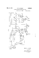
- Fig. 1 shows a preselector circuit comprising a primary nder LFl, a secondary finder LF2 and a distributor switch D.
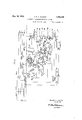
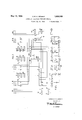
- Fig. 2 shows a selecting circuit at the first numerical switching stage.
- a first conversa.- tion group nder is indicated above the broken line whilst below this line is illustrated a control circuit common to a group of finder switches.
- the control circuit comprises a control switch R1, a. bye-pass switch R2 and an associated group of relays.
- the controly switch R1 is equipped with wipers and banks 2 to 8 whilst the bye-pass switch R2 is equipped with wipers and banks C12, M12, M22, T12, T22, -1, -2, +1, +2, N21
- Bye-pass conductors extend 4from the 5 terminals of the banks -1, 2, +1, +2 of the switch R2 to control circuits at the succeeding switching stage, and bye-pass test wires extend from the terminals of the banks T1, T2 to finder switches at the succeeding switching stage.
- the terminals in the marking banks M12, M22 are multiplied to corresponding terminals in the marking banks M of all the finder switches served by the control circuit.
- the control circuit as shown is arranged to absorb a iirst digit 6. Such a provision is desirable in circumstances wellknown in the art and which it has not been thought necessary to enter into.
- two groups of terminals of the bank 7 of the switch R1 are strapped to the terminals of the control bank C12. Normally the first group is used for marking in the bank C, but if the digit 6 which is to be absorbed is dialled the switch R1 advances to the beginning of r the second group of terminals without making an effective marking, but in response to a further digit a marking is effected over a selected terminal of the second group.
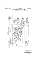
- Fig. 3 shows a selecting circuit at the second switching stage.
- a second group finder is shown above the broken line, whilst below this line is indicated a control circuit comprising a control switch R1 equipped with wipers and banks 1, 2, 4, 5, 6, 7, 8, 9 and 10 and a bye-pass switch R2 equipped with wipers and banks C13, M23, M13, T23, T13, +2, 1, 2, +1 and N2.
- the banks or these switches are arranged similarly to those of the switches Rl, R2 of the control circuit illustrated in F ig. 2 with the exception that the digit absorbing feature is omitted.
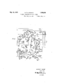
- Fig. 4 shows a selecting circuit at the third or penultimate switching stage.
- a penultimate group finder is indicated above the broken line and below this line is shown a control circuit comprising a control switch R1 equipped with wipers and banks 1,2, 4, 5, 6, 7, 8, 9 and 10 and a bye-pass switch R2 with wipers and banks C14, M24, M14, GM, T24, T14, +2, 1, N21 and N22.
- v The banks of the switches R1, R2 are arranged in similar fashion to those of the corresponding switches in Figs. 2 and 3.
- the terminals of the bank OM are connected to overflow metering devices.
- FIG 5 shows a linal selecting circuit.
- a Linal iinder is indicated above the broken line and below this line is shown a control circuit comprising a control switch Rl with wipers and banks 1 9, and a bye-pass switch R2 with wipers and banks X2, X1, M25, M15, T25, T15, C and N2.
- rFerminals oi the banks 7, 8, 9 in certain positionsl of the switch Rl are used for control purposes, whilst terminals of the banks l, 2, 3, 4, 5' and 9 in other positions are used for associating the control circuit with a particular iinal finder.
- Banks X1, X2 of the switch R2 are used for F.
- B. X. discrimination Terminals in the banks T15, T are multipled to corresponding terminals in the ⁇ ind-er banks H and terminals in the banks M15, M25 to corresponding terminals in the iinder banks M.
- Fig. 6 shows a modified 'form ot selector circuit adapted to give access to 20() lines and illustrates above the broken line a converse tion selector circuit comprising ⁇ two associated single-motion non-homing iinder switches A6 and B6.
- the switch A6 is equipped with wipers -A, +A, HA, MA and the switch B6 with wipers B, l B, HB, MB.
- Below the broken line is shown a control circuit common to a group of conversation selector circuits and comprising three switches.
- a switch Rl the banks of which are indicated 1 10
- a switch R2 the banks of which are in- (nested no, atie, Ain, irre, irri, iii-2,
- A-tl, A-2 and A-L and a switch B3 the banks of which are indicated BC, BM2, BM1,BT2,BTl,B+2,B+l,B-2 andB-l.
- the switches R2 and are each equipped with two sets of wipers. Access is had to byepass conductors extending to the next switching stage over banks AT2, AT1, kd-2, .Pr-t1,
- Fig. 6a is a diagram showing the arrangement of the marking wires between the control switches R2, R3. andV the conversation switches A6, B6.
- Marking wires extend from the banks BM2, BM'l to the control bank MB or the switch B6 and from the banks AM2, AMl to the control bank of the switch A6.
- Group marking wires also eiltend from the first positions in the bank ot the switch Bl' to the control banks LC and BC of the switches R2 and R3, respectively.
- the later positions oi' the switch R1 are used for operatively connecting the control circuit to an" one of its associated conversation selector circuits over the banks l to l0.
- Fig. 7 illustrates a method whereby a group of conversation switches may be switched trom a faulty control circuit to an adjacent control circuit which normallyY serves a different group of conversation switches.
- Fig. 8 is a schematic diagram illustratingI the general layout of a typical system.
- the finder switches comprise 100 point single motion step-by-step switches of the ilo-normal type having two sets of wipers arranged 1800 apart each wiping an arc of contact sets during one complete revolution of the switch sha-ft.
- the switches R1 are 50-point step-by-step single motion switches. As in some cases less than halt of the number of positions in the bank of Rl is required for marking purposes and for connecting the control circuit to the associated selector switches, the bank may 'nave a second normal position, and have two corresponding groups of positions in the first and second halves ot the bank, corresponding contacts being connected in parallel 'or the same marking or connecting function.
- the switches B2 comprise 100 point single motion step-by-step switches having two sets of wipers arranged to wipe simultaneously over corresponding sets of bank levels.
- a calling subscriber S becomes connected over a line circuit LC and irst and second line finders LFl, LF2 controlled by a distributor D to a free irst group iinder S associated with an idle control circuit C.
- rhe virst digit dialled sets the control switch Rl which marks the wanted group in the bank of the bye-pass switch R2, which commences to advance immediately the impulses start arriving.
- the bye-pass switch R2 searches for an idle second group finder Si having an idle associated control circuit C1 and at the same time the switch R1 hunts for the first group finder S which is to replace the byepass.
- the group finder S is then set on the trunk selected by the bye-pass switch R2.
- the R1 switch of the selected control circuit C3 responds tothe tens and units digits and marks a wanted line S4 in the bank of the R2 switch.
- the R1 switch associates the control circuit C3 with the selected final finder S3 and a test is made ot' the condition otthe wanted line in the control circuit C3.
- lf the wanted line is busy, a busy signal is given, whilst it the line is idle the finder S8 is advanced to it and ringing current is applied.
- the control circuit C2- is released when the R1 switch of the control circuit C3 has picked up the final nder S3. Vrlhe release ot the control circuit C2 brings about the release of thecontrol circuit C3.
- a subscribers line terminates at the exchange in the banks ot primary finders, such as LF, and also in the banks of the connector switches, which are not shown.
- the subscribers lines are formed into groups, and there may be as many lines in a group as there are sets of contacts in the banks of the iinders LF1, say 100, there being a sulicient number ot' finders provided for each group of lines to handle the traliic from that group.
- a common start relay SA is provided for each group ot subscribers lines.
- the secondary finders LF2 are linked to first group nders and are divided into groups of sufficient size to handle the traliic which will be directed through them. Each of these groups of secondary finders is arranged to search for a different primary linderin each of the primary groups. Associated with each group of secondary finders is an allotting and controlling switch D which preselects an idle secondary finder linked with an idle first group finder the control circuit associated with which also is idle. Preferably therefore the number of allotting switches D is equal to the number of groups of secondary finders and to the number of primary finders in each group.
- a starting relay SA common to the subscribers group marks all the primary nders LFl serving this group and starts a set of secondary linders LF2 preselected by the allotting switches D. These secondary finders LF2 hunt until two have reached marked primary finders LF] and the two engaged primary finders then hunt until one finds the calling line.
- the originating trailic is assumed to be sul'cient to necessitate 12 primary linders per group, and in consequence there are provided 12 allotting switches and 12 groups of secondary finders.
- the first group of secondary finders will have access to the first primary finders of each group of primary finders
- the second group of secondary nders will have access to the second primary finders of each group of primary linders and so on to the twelfth group of secondary .finders which will have access to the twelfth primary finder in each primary group.
- each distributor switch D completes the following circuit contacts B2, J3, winding ot relay lLvdistributor wiper DT, wire T, contacts HS2, Figure 2, B2, P1, Q1, E10, wipers of switches R1 and R2 in their home positions, contacts B7 to battery.
- Relay H closes a circuit via El, F8, K7, H3 wiper F21 and interrupter springs of a switch magnet (similarly designated in other parts of the drawings) for the stepping magnet F22 of the associated secondary finder LF2.
- a circuit is prepared for the test relay E over contacts H1, K5, wiper F2T or" the distributor switch D and wiper C ot' the secondary finder LF2.
- a spark quenching condenser is connected to the magnet F 22 over wiper SQ2.
- the secondary finder LF2 steps until it reaches a marked primary finder LF1 thereby causing the response ot relay E which opens the circuit of the driving magnet F22 at contacts El and closes at E2 a circuit via HE2 for relay'F which locks via contacts F9, .l2 and prepares a circuit for test relay B at contacts F42. y y
- rlhe relay HA will not operate in series with a single relay E, but when a secondary nder controlled from another distributor switch also engages a marked primary iinder there will be two E relays in parallel and relay HA will operate and open at contacts HAl the circuit to the marking contacts via its non-inductive winding and battery thereby preventing other E relays Jfrom operating.
- a relay HE is energized over contacts K6, H2, distributor wiper MN, wiper and multiple Contact L of the secondary finder Ll4 ⁇ 2, multiple contact such as L and wiper of the secondary tinder already engaging the primary linder, trontcontacts such as KSl or HSl of the attaching or switching relay KS or HS, Fig. 2 et the group tinder ot the engaging secondary finder link, and the grounded hold wire H.
- Relay HE operates and at contacts HE2 holds open the circuit of relay F and closes an alternative circuit for the stepping magnet F22 independent of relay E, so that the secondary inder continues to advance.
- a primary linder will be taken into use, however, it it is idle, even it it is standing on a busy line since in this case the multiple L will not be grounded.
- relay HA When relay HA operates it opens at contacts Hl'l2 the starting circuit ot the J relays of the various distributor switches but by this time relays J of the distributor switches associated with secondary iinders which have seized marked primary tlnders have been held energized via contacts Kl and F1.
- the operation ot relay F also completes a circuit tor the stepping ⁇ magnet Fll ot the primary iinder Lll via contacts Bl, F2, distributor wiper F12 and tinder wiper B.
- rEhe common spark quenching condenser is now conected to the magnet F22 via contacts F7 and wipers SQA, SQ. llfhen a.
- primary tinder engages the calling line relay B is energized via contacts Fa, wiper lllrl of the distributor switch D, wipers H ot the secondary and primary tinders, and the subscribcrs cut-oli' relay KA.
- Relay B locks up over contacts F5, Bl and at contacts B2 opens the circuit ot relay H.
- Relay B also opens the circuit of the stepping magnet Ell at contacts Bl and closes a circuit via contacts Bl, F6 for relay K u hich at contacts Kl opens the circuit of relay J, and at contacts opens the circuit oll relay E.
- Relay l? now relapses and opens the circuit of relay B at contacts F5.
- relay l locks over the make etore break contacts F6 and contacts K3, Hl.
- A. circuit is now completed from ground at contacts Hl, F3, K2, interruptor contacts and magnet D ot the distributor switch which rotates to find an idle secondaryT link the associated finder and its control circuit of which are also idle.
- relay H energizes over contacts B2, K9, wiper DT and the test wire T, and at contacts Hl opens the stepping circuit and unlocks relay K which in turn cle-energizes relay H.
- the relay HE is energized over contacts K6 the wiper CM, multiple contact, wiper such as CM of the other distributor to ground at contacts such as K4.
- An alternative ground is thereby provided for the relay K and magnet D via contacts Kel, HEl and the distributor switch continues to step in spite of the momentary response ot relay HE.
- a circuit is now completed for relay A from battery and one winding of relay A., H3, KS2, negative wire, subscribers loop, positive wire Q53, H5, second winding of relay A to ground.
- Relay A completes the obvious circuit Jor relay B over A2 and relay B opens the testing circuit at B2 and closes a locking circuit for KS through B3 and KS.
- B7 opens the circuit to the battery and energizes the relay lil.
- At the tirst interruption relay l releases but relay B being ot the slow release type remains operated and completes a circui J for the magnet Rl through E4, B5, winding ot relay C and Al to ground.
- At the end of the interruption relay A reoperates and the switch Rl steps into position 2.
- the circuit ot relay M is opened and when relay M releases a circuit is completed for the magnet R2 through H8, interrupted springs, Ml, wiper and home position or" the bank N21 of switch B2, C2, Q1, Pl, B3 to ground.
- the switch B2 takes a step and continues stepping by means of its own interrupter springs and the off normal contacts of the bank N21 to ground at E6 until relay lvl reoperates.
- rlhe switch Rl takes one step for each impulse received from the subscribers dial and the strapping between the banks n group are engaged, the switch R2 will operated 7 and C12 is so arranged that the circuit for relay M is completed whenever the R2 switch reaches the commencement of the group corresponding to that on which the R1 switch is standing.
- relay C will release after a period and when relay M operates due to the switch R2 having reached the position indicated by the bank 7, relay M will reoperate, as already described. and a circuit will then be completed for relay E from battery and winding of relay E, G4, V, C1, W74, M2, wip er and oit normal contacts ot the bank N21, E6 to ground.
- Relay E closes its light-spring contact E9 and locks over its second winding to ground at B3.
- E10 opens the circuit for relay M which releases and recloses the driving circuit of the R2 switch through M1, wiper and ott' normal contacts ot the bank N21, E5, Q1, P1 to ground at B3.
- Relay M will open the driving circuit of the switch R2 at M1, and close at M2 a. circuit tor relay G through E8.
- Relay G is of the slow to operate type and will not operate during the period when both relays E and M are during the initial operation of the former. However, on the last contacts of the group the circuit for relay G is maintained and this relay will eventually operate and connect at G7 the busy tone to the calling subscriber from lead BT.
- relays T and H are operated pleted for the TWhen relay E operated a circuit was com pleted for the switch R1 through E3, the interrupter springs, and T1 to ground. This will cause the R1 switch to continue stepping until the relay T operates through wiper and bank contact 2, contacts KS to ground at B3.
- HS will operate and HSG will extend ground over the H wiper to the H wire ofthe succeeding finder in order to mark that switch to the succeeding control.
- n Contacts HS3 and HS4 will prepare the permanent circuit to replace the bye-path.
- HS5 grounds the H wire to hold the cut-oli1 relay independently of the control circuit. The control circuit does not release until the ground potential is removed from the T12 or T22 wire by the succeeding control circuit.
- the relay H operated the circuit for relay A was opened and relay B released also after a short period. Relays E, KS and T where maintained, however, by the ground potential on the test wire, which is'maintained by the succeedingcontrol circuit under the control of the calling subscribers loop.
- the succeeding finder removes ground from the T wire, relays T, KS and E, M and H release.
- the homing circuit for the switch R1 is completed through E4, B4, H7, o'l" normal contacts and wiper ot bank 3, interrupter springs T1, to ground.
- the homing circuit for the switch R2 is completed through H8, M1, wiper and ott normal contacts N21, E6, to ground.
- Relay P will cause the operation of relay H and the subscribers loop will be switched via H2 and H4, J6 and J8 through the home contacts ot the banks --1 and +1, G8 and E2, back to the relay A.
- relay E When relay E operated, it closed the driving circuit ot the magnet R1, as already described and this switch will step forward until relay T operates.
- Relay T will close a circuit, as already described,
- relay M When the tlnder has been driven to the terminals corresponding to those on which the switch R2 is standing (i. e. its home terminals), relay M will operate and a circuit will be closed for relay G through E8, M2, wiper and home contact of the bank N21, M4, H9 and T2 to ground.
- G1 closes a circuit for the relay HS which is maintained through HSG, H wiper and home contact of the nder S, home contact and negative wiper, HS3, subscrihers loop, HS4, positive wiper and home contact, to ground.
- the operation ot G6 opens the circuit for relay A which releases and opens the circuit for relay B.
- Relay B in turn opens the circuit for relays E, G.
- the finder relay HS is maintained operated over the subscribers loop until the subscriber releases. The same operations occur if the subscriber Jfails to dial a second digit after the switch R1 has gone to its 11th poy sition after responding to the digit 6.
- this selector circuit with its associated control circuit is test- TTG, P1, Q1, E11, the wiper and home contact ot bank 9, of switch R1 the home contact and wiper of bank C13 of switch R2 B5, to resistance and battery. It this resistance is connected to the test wire, the previous control circuit will switch through extending the suhscribers loop to conductors and thereby, causing the operation of relay A through H2, H4.
- Relay A closes the obvious circuit for relay B through A2.
- Relay B places ground on the test wire at B1 and removes the battery from the test wire at B5.
- a circuit is closed tor relay M from battery and winding ot relay M, H14, B6, wiper and home contact of the bank C13, home contact and wiper ot the bank 9, E11, Q1, P1, TT6, B1, t ground.
- relay A releases but relay B being of the slow release type, remains operated and completes a circuit for the magnet R1 through E3, B2, winding of relay C and A1 to ground.
- the switch R1 steps into position 2.
- the circuit for relay M is opened by the wiper 9 and when M releases a circuit is completed for the magnet R2, through its interrupter springs, H7, M1, wiper and home position ot the bank N2 of switch R2, G1 of B1, to ground.
- the switch R2 takes a step and continues stepping by means of its own interrupter springs and the ott' normal contacts of the bank N2, to ground at E until relay M reoperates.
- the switch R1 takes one step for each impulse received from the subscribers dial and the strapping between the banks 9 and C13 is so arranged that the circuit for M is completed whenever the R2 switchi reaches the commencement ot the group corresponding ⁇ to that on which the R1 switch is standing.
- relay C When the digit is completed, relay C will release after a period and when relay M operates due to the switch R2 having reached the position indicated by the bank 9, relay M will operate as already described and a circuit will then be completed for relay E from battery and winding ot relay E, G3, C3, M2, wiper and off normal contacts of the bank N2, E5, to ground.
- Relay E will close its light spring contact E10, and lock over its second winding to ground at B1.
- E11 opens the circuit for relay M which releases and recloses the driving circuit ot the R2 switch through H7, M1, wiper and ott" normal contacts of the bank N2, E4, Q1, P1, TT6, to ground at B1.
- T relay P alone operates the driving circuit of the switch will be opened at P1 and at P2 a circuit will be closed for relay H which will lock up via H5 through TTS to ground at B1.
- It relay Q operates a driving circuit of the switch will be opened at Q1, and at Q2 a circuit will be closed for relay J which will operate and close at J 1 a circuit for relay H which will also operate.
- H5 will provide a locking circuit for both the relays H and J. The proper wiper set will be connected up at contacts J -J 8.
- the switch R2 will step eventually to the last contact of the group, in which position a circuit will be closed for the relay M through H14-, B6, wiper and bank contacts C13, E12. Q1, P1, TTG, and B1 to ground.
- Relay M will open the driving circuit of the switch R2 at M1, and close at M2 a circuit for relay G through E7.
- Relay G is of the slow to operate type and will not operate during the period when both relays E and M are operated during the initial operation of the former. However, on the last contacts of the group the circuit for relay G is maintainedand this relay will eventually operate and connect at G9 the busy tone over wire T to the calling subscriber.
- TT1 and TT2 extend the subscribers loop to relay A through the wipers and contacts of banks 1 and 2 thereby replacing the bye-pass over conductors -land Contacts TT3 remove the ground from the test wire causing the release of the previous control circuit.
- TT4 provides a locking circuit tor the relay T and extends the ground to the hold wire to hold the previous switching relays.
- Relay G will operate and close the circuit for relay HS through bank contact and wiper 6, G1, M4, TT7, H8, to ground.
- Relay HS will operate and HS6 will 'extend ground overthe H wiper to the H wire of the succeeding linder in order to mark that switch to the succeeding control.
- Contacts HS2 and HS3 will prepare the iermanent circuit to replace the bye-path.
- HSl grounds the H wire to hold the previous switches independently of the control circuit. The control circuit does not release until the ground potential is removed from the T wire by the succeeding control circuit.
- the relay H operated the circuit for relay A was opened and relay B released also after a short period.
- Relay P will cause the operation of relay H and thel subscribers loo will be switched via H1 and H3, J 6 and J8 through the home. contacts of the banks -1 and +1, G8 and E1, back to the relay A.
- relay E When relay E operated, it closed the driving circuit ot the magnet R1, as already described and this switch will step forward until relay T operates.
- Relay T will close a circuit for the relay TT, which as already described closes a circuit for the finder magnet S.
- relay M will operate and a circuit will be closed for relay G through E7, M2, wiper and home contact of the bank N2, Ma, TTT and H8 to ground.
- Gl closes a circuit for the relay l'lS which is maintained through HSG, H wiper and home Contact of the finder S, home contact and negative wiper, HS2, subscribers loop, HSS. positive wiper and home contact, to ground.
- rllhe operation of G8 opens the circuit for relay A which releases and opens the circuit for relay B.
- Belay B in turn opens the circuit for relays E, G, H and T causing the switch B1 to return to normal.
- the iinder relay ltlS is maintained operated over the subscribers loop until the subscriber releases.
- a finder with its associated control circuit is tested in a similar manner to the second group selector circuit through BSl, GSS, TTS, T'l, P2, Q1, E12, wiper and home contact of the bank 10 ot the Bl switch, home contact and wiper of the bank C14 ot the R2 switch. B6 to protective resistance and battery. It the nder and control circuit are found to be free, the preceding control circuit switches through the calling subscriber by means ot the bye-pass negative and positive wires thereby completing a circuit for relay A over H1.
- Relay A completes the obvious circuit for relay B and a stepping circuit tor the magnet R1 similar to that described for the absorbing'and group selector circuits.
- the stepping of the switch R2 is completed through Ml, the wiper and home contact of the bank N21, Cl and B1 to ground.
- lVhen on the completion of dialling tbe switch B2 reaches the commencement of the group, the circuit for relay E is completed through Gl, C3, M2, wiper and ott' normal contact of the bank N21, H5, Ea to ground.
- Relay E completes the testing circuits for relays P and Q at ll and E15 respectively and should a tree outlet be available relay P and Q will close the circuits for relays H and J, as alreday described.
- the penultimate control circuit remains in service While the last two digits are being received by the iin al selector circuit and the called line tested. After the linal selector circuit has completed the test, it removes ground from the test Wiper T13 or T23 which was holding the penultimate control circuit causing relay E to release. A circuit is now completed for relay GS through AS2, contact and wiper of bank 6, TT6, non-inductive resistance, E6, TT'?, to ground. rlhe non-inductive resistance is of such a value that the marginal relay BS will not operate in multiple with GS.
- the final inder has placed a ground potential on the H wiper of the enultimate finder in which case it will be ied back through BSS, contact and wiper ot bank 7, M3, E7, TTG, wiper and contact of bank 6 to relays GS and BS in which case both relays will operate.
- the ground potential will only be placed on the H wiper by the linal iinder when the called subscribers line is free as is explained later.
- the operation of relay GS will complete a circuit for relay AS via GSl, DS1, subscribers loop DS3, GS6.
- Relay A provides a holding ground for relay GS; relay BS in operating completes the ringing circuit through FS4, BS?, called subscribers loop BSt, FS2, the ringing tone battery RR.
- relay FS operates and completes a circuit for relay DS through FSI and FSS.
- the relay DS operates it reverses the direction of current in the called subscrbers loop for metering purposes. Talking current is supplied to the calling and called parties through relays AS and DS respectively.
- DS6 provides a locking earth for relay BS; the calling subscriber on releasing causes the relay AS and subsequently the relay GS to release and at GSG remove the ground holding the preceding switches which are made to release.
- the penultimate finder will remain operated as long as the relay DS is held by the called subscriber.
- Relay BS which is held by relay DS prevents the penultimate finder being taken into use by opening contacts BSl.
- lf the called subscriber releases first relay DS makes the circuit of relay BS dependent upon relay GS and the called subscriber is held until the calling subscriber releases: during this time a signal is given via DST and FSS to the supervisory zlarm over lead GSH.
- lf the called subscribers line is engaged and relay GS opcrates without relay BS the busy tone lead BT is connected up at GSS and BS5 to the calling subscriber.
- GS5 opens the circuit for relay T which in turn opens the circuit for relay TT causing the release of the control circuit.
- relay G will be operated over the following circuit B5, G2, E10, M2, wiper and off normal contact of the bank N21, H5, E3, Q1, P2, TT'5, B1 to ground.
- Relay G will extend ground from B1 through G5 and E5, non-inductive resistance, TTG, to wiper and contact of bank 6, to cause the operation of relay GS which will connect the busy tone circuit to the calling subscriber, as already explained.
- a final nder with its associated control circuit is tested over the wire T, HS1, T8, wiper' and home contact of the bank C5 of the switch R2, the home contact and wiper 9 of the switch R1, V6, B7, protective resistance to battery.
- the negative wire is extended over the bye-pass to relay A which operates and operates relay B over the obvious circuit.
- Relay locks over at G6 through E6 to ground at B5.
- Relay G completes a circuit for the magnet R, through G4, strapped contacts in positions 2 to 11 and wiper of bank 7 M1, and interrupter springs to ground causing the switch R1 to take a step to its next position in which the circuit for relay M is opened and the driving circuit for magnet Rl replaced by G2, the strapped contacts in position 2 to 11 and wiper of bank 8 of the switch R1, and H1 and M2.
- the switch R1 continues to be stepped by this circuit unitl it reaches position 12 where it awaits the units digit.
- the stepping for the units digit is simlar to that descrbed for the tens ex cept that the switch R2 has no circuit until relay C releases the second time.
- the switch R2 then steps through P2, C2, contact and wiper ofrbank 8 of switch R1, H1, M2, intcrrupter springs of the switch R1 to ground until relay M operates when the R2 switch is standing on a position marked by the R1 switch.
- Relay M completes a circuit through the wiper and contact of bank 7 to the relay E which operates and locks through V1, E?, B5 to ground.
- Relay E opens the circuit for relay G at E6 but while G is releasing, this relay bein@ of the slow to release type, a testing circuit is completed from ground at H7, G9, TR1, E8, winding of relay P, J6 or J7 to the test wiper T25 or T15.
- Relay J is the discriminating relay and is operated when the R1 switch steps for the tens digit on alternate contacts only of bank 1 of the switch R1 which are grounded. Tf the switch R1 is on one of' these alternate positions when relay G operates, relay J willl remain operated through G8, J1, T3, B5 to ground.
- relay J If relay J is not operated when relay G operates it will have no further opportunity. If the line called is free relay P will operate and close the obvious circuit for relay H. When relay G releases a circuit is completed for the magnet R1, through T2, El, G1 and the interrupter springs to ground. This stepping will continue until the relay T operates through E5, the wiper and contact of bank 2, and HSS to the hold wire of the final finder which has been predetermined by the penultimate selector circuit. The ground at the interrupter springs of magnet R1 is then extended through G1, E1, T1, H6 and M4 to the wiper and Contact of bank 4.- and final finder magnet S. At the same time relay M is extended through B8, V6, wiper and bank contact 9, to the marking wiper M of the final finder.
- relay M is extended to the marking wiper M or M15 of the switch R2, J l or J5, H8 to ground.
- Relay M opens at M4 the circuit for the final finder magnet Si and closes the circuit at lal through wiper and contact of bank 3 tor relay HS which locks through ll-llL to the test wire which is grounded from B5 over H9, J6 or JT, and wiper T or T15.
- H51 opens the bye-path test which releases the penultimate control and HS2 places the ground potential on the H wire causing the operation ot relay BS in the penultimate finder.
- discriminating bank X1 or X2 causes tlie operation of relay M which opens the d i circuit of the magnet B2 and causes the reoperation of relay E.
- Relay G will release after a period opening the circuit tor i lay V at G10. Due to the tact that rel TT l not operated when relay T operates, signal is passed back to the finder. Should it ha een that the subscr- .L 1 fails to dial a pulse circuit is completen the two-ste rela i TP. via B9 C3 TP/l E m f v 7 1 an and the pulse wire lP, and at the end o; t pulse, relay TP will be locked up over lieht contacts TP2.
- the restoring circuit for the magnet B1 extends via T2, E3, B2, and the ott-normal bank 6, whilst that for the magnet B2 extends via the oil-normal bank N2 and B5.
- It the num-- ber dialled is one of a P. B. X. but not the first line, automatic limiting will not take place due to the fact that the battery potential is only connected to the irst line of the group.
- the cross connection between the bank C ot' the switch R2 and the bank 9 ot the switch R1 is such that consecutively numbered lines may both be P. B.. X. groups oi' more than one line due tothe fact that the switch R2 steps round until it reaches 'he position marked by the switch R1.
- selector circuit can be substituted in the system previously described in place of the selector circuit shown in Figure 3.
- the selector circuit with its associated control switch is tested through thev wire T, contacts HSl, TTS, TTG, P2, Q1, E9, the wiper and home contact of the bank 10 of the switch R1, home Contact and wiper AC of the switch B2, B7, the home contact and wiper of the bank BC of the switch R3, B4, to resistance and battery. If this resistance and battery is connected to the test wire the previous control switch will be able to switch through in the manner described in the call already tollowed out, extending the subscribers loop to BP+ and BP- thereby causing the operation of relay A through H6 and H7.
- Relay A closes the obvious circuit for relay B through A2, and relay B places ground on the test wire at B1 and removes battery from the test wire at B7 and B4.
- Relay C is also of the slow release type and remains operated during the series of impulses. Relay C also closes the following circuit for the magnet R2, through its interrupter springs, D4, the wiper and home Contact ofthe bank N2, C2, Q1, P2,
- relay C will release after TT6, B1, to ground.
- the switch R2 opens its own circuit when it steps off normal. When the switch R1 steps into position 2 at the end of the first impulse the circuit for relay M is opened by the wiper l0 and when relay M releases the circuit for the magnet R2 is again completed through the oii normal contact of the bank M2, M2, H3, E4 to ground. The switch R2 continues stepping by means of its own interrupter springs until relay M reoperates.
- the switch R1 takes one step for each impulse received from the subscribers dial and the strapping between the banks 10 and AC is so arranged that the circuit for relay M is completed whenever the switch R2 reaches the commencement of the group corresponding to that on which the switch R1 is standing.
- the switch R2 has access to 100 outlets which will serve a. numer of groups which are themselves dii'erentiated by the setting of the switch R1 in response to the dialled impulses. Other groups are reached by the banks ot the switch R3 and a discriminating relay D is provided to operate when the switch R1 reaches the iirst group connected to the switch R3.
- This circuit may be traced from battery, winding of relay D, D5, wiper and bank Contact 10 of the switch R1, E9, Q1, P2, TT6, B1 to ground.
- Relay D locks through D6 to ground at B1.
- It relay D is caused to operate the circuit for relay M is transferred through D10, H15, and B5 to the bank BC of the switch R3 and the commoning between the bank 10 of the switch R1 and the bank BC is so arranged that the circuit tor relay M is completed whenever the switch R3 reaches the commencement of the group corresponding to that in which the switch R1 is standing.
- the driving circuit of the switch R3 extends over the interrupter contacts, D3, off-normal bank N2, M2, H3, E4, and after the switch has moved a step, over its oil-normal bank N3.
- relay P alone operates, the driving circuit of the switch will be opened at P2, at P1 a circuit will be closed for relay H which will lock up through H1, and TTG', to ground at B1.
- relay Q operates, the driving circuit of the switch will be opened at Q1, at Q2 a circuit will be closed for relay J which will operate and close at J 1 a circuit for relay H which will also operate.
- It all the outlets of the group are engaged the switch R2 or R3 will step eventually to the last contacts ot the group in which position a circuit will be closed for relay M through D9 or D10, H13 or H15, B6 or B5, wiper and bank Contact AC or BC, E10, Q1, P2, TTG, B1 to ground.
- Relay M will open the driving circuit of the switch at M2 and close at M1 a circuit for relay G.
- Relay G is of the slow to operate type and will not operate during the period when relay M is operated and relay C normal, during the initial operation of the former. However, at the last Contact of the group the circuit for relay G is maintained and this relay will eventually operate and connect at G3 the busy tone to the calling subscriber over lead BT.
- /Vhen relay E operated a circuit was completed for the switch R1 through E2, interrupter springs T1 to ground. This will cause the switch R1 to continue stepping until the relay T operates through the wiper 3, contacts HS2 and the hold wire H to the preceding' selector.
- the magnet SB will cause itsl wipers *B, +B, HB and MB to step until the following circuit is established :battery and winding of relay F, D18, H16, J6 or J7, wiper and bank Contact of the bank BM2 or JM1, multiple wire to the contact and wiper MB of the selector, bank contact and wiper of bank l0 of the switch R1, TTS, Q1, P2, TT-to ground.
- Relay F in operating completes the circuit for relay HS via F1, D1, TT7, H4.
- the circuit for the magnet SB will be opened by the operation of relay F which is connected through D17 to a certain predetermined bank contact of the bank MB of the switch B6 and the circuit torthe magnet SA will be opened by the operation ot rela-y M through D9, H14, Jl or J5, the wiper and bank contact of the bank AM1 or AM2, multiple wiring to the bank contact and wiper ot bank MA of the selector, bank contact and wiper 9 ot the switch R1, TTS, Q1, P2, T5, to ground.
- the wipers of the switch A6. may be connected to two,
- this arrangement is not limited to two permanently associated switches and that if the number of groups of outlets is suiiicient a further switch Re may be added to the control circuit which will operate under the control ot a further discriminating relay similar to D and a further switch (c) will be added to the selector circuit and connected through a predetermined position or positions on the bank of the switch A.
- FIG. 7 shows a. method whereby a group of conversation switches may be switched trom a faulty control circuit to an adjacent control circuit which normally serves a different group of conversation finder switches.
- the figure illustrates suiiicient ot the circuit of two control circuits C1 and C2 and certain ot their associated conversational finder switches for a complete understanding oi the arrangement.
- Two conversation finders 1 and 2 ot the group ot, say ten conversation finders associated with the control circuit C1, and one conversation finder ot the group associated with the control circuit C2, are shown.
- B131 represents the wipers of the bye-passing switch associated with the control circuit Cl, and BP2 the wipers ot' the bye-passing switch associated with the control circuit C2.
- Each conversation linder is provided with an attaching relay KSl, KS2, or KS2() holding relay HSl, HS2, or HS20, and stepping magnet S1, S2 or S20.
- Three multiple wires extending from the control circuits and adapted to be operatively associated with the talking group iinder over contacts ot' the KS relays are shown.
- Relay H (or H1) applied a marking potential to a marking contact of the selected trunk over the4 winding or test relay M (or M1) and front contacts 1 of relay H (or H1) connects an opposite potential to the control wiper M of the conversation finder switch over front contacts 3 ot relay H (or H1), back contacts of a relay @Q1 (or @2Q-2) and front contacts of relay KSl, (or KS2' or KS20), and closes a steppingz circuit for the magnet SL (or S2 or S20) 4terraces of the conversation finder over back contacts of relay M (or M1), front contacts 2 of relay H CSor H1), back contacts of relay QQl (or Q 2) and front contacts of relay KSl (or KS2 or KS20).
- l/Vhen the conversation iinder switch reaches the marked trunk, test relay M (or Ml) energizes and opens the stepping circuit of the S magnet. 'Ihe Vcontrol circuit is detached subsequently as previously described.
- each control circuit Cl or C2 is provided with a change-over relay QQI or QQ2 which when energized switches over the multiple wires from its own control circuit to the other.
- rlhe circuit of this relay QQI or QQ2 may be completed manually by throwing a change-over key QK or the relay may be automatically energized by causing a faulty relay (not shown) to earth the wire F.
- the marking contacts of the byepass must be multipled over all the conversation finders of the two groups, and to ensure that there will be no confusion when both control circuits are operative, the marking condition must be such that the test relay M or M1 of one control circuit will not operate due to a marking potential from the other control circuit.
- relay M is connected to battery and the associated selectors search for a battery potential
- relay M1 is connected to ground and the associated conversation linder switches search for an earth potential.
- test relays M, M1 may be placed in the control circuit in the leads which are extended to the conversation iinder switch marking wipers. In this case as it is possible for both conversation finders switch wipers to rest on contacts belonging to the same outlet the test relays must be designed not to operate in series.
- the wipers of the switch Rl are arranged to give access to conversation finders of two groups, viz., those of the group to which the finder illustrated belongs, and in later positions to finder ot an adjacent group normally served by another control circuit.
- the wiper 2, Fig. 2 searches over the positions allotted to that group to which the finder shown belongs, but if the control circuit normally serving the other groups becomes faulty a relay -such as QQl, Fig. additional wiper l (over contacts QQ) which is arranged to search over the finders of this other group. In this manner the control circuit shown is made to serve the two groups of iinders.
- a telephone system a plurality of switching stages, a plurality of conversation switches at each switching stage, control circuits associated with said plurality of conversation switches at each switching stage, a byepass circuit extending from one switching stage to another, and means under control'of said control circuits at one switching stage whereby an idle conversation switch and a control circuit at the second switching stage are taken in use oversaid vbye-pass circuit extending from a control circuit which has been selected for use with a conversation switch at the preceding switching stage.
- a telephone exchange system the combination of an vautomatic switch having a group of outlets, an auxiliary switch of the singlevmotion type which responds to digit impulses, means for transmitting such impulses to said auxiliary switch, means according to the value of the first digit received by said auxiliary switch to cause the advance of said automatic switch to a wanted group of outlets or to control the advance of the auxiliary switch to a predetermined intermediate position, means in response to a second digit impulse to thereafter advance the automatic switch to a group of outlets determined by the second digit.
- two permanently associated switches provided with wipers, the wipers .of one switch being directly connected to wipers of the other and the wipers of the other connected to a particular set of bank contacts of said first switch, and means provided for advancing said iirst switch alone or for simultaneously advancing both of said switches.
- a telephone system comprising a plurality of switching stages, each stage having a plurality of conversation switches, control 7, connects to the wiper 2 an
Landscapes
- Engineering & Computer Science (AREA)
- Computer Networks & Wireless Communication (AREA)
- Monitoring And Testing Of Exchanges (AREA)
Description
7 Sheets-Sheet l E. P. G. WRIGHTk Filed July 12, 1929 AUTOMATIC TELEPHONE EXCHANGE SYSTEM May 10, 1932.
ATTORNEY May 10, 1932.
E. P. G. WRIGHT AUTOMATIC TELEPHONE EXCHANGE SYS'GEM Filed July 12, 1929 "7' Sheets-sheet 2 ESMOND P G WRIGHT INVENTOR ATTORNEY May 10, 1932.
E. P. G. WRIGHT AUTOMATIC TELEPHONE EXCHANGE SYSTEM Filed July 12. 1929 7 Sheets-Sheet 3 NLL. EL.
ESMOND P. G. WRIGHT INVENTOR ATTORNEY May 10, 1932 E. P. G. WRIGHT AUTOMATIC TELEPHONE EXCHANGE SYSTEM Filed July l2. 1929 7 Sheets$heet 4 `Esa/mln P. G. WRIGHT INVENTOR ATTORNEY May l0, 1932- E. P. G. WRIGHT AUTOMATIC TELEPHONE EXCHANGE SYSTEM Filed July l2, 1929 7 Sheets-Sheet 5 ESMOND F? G. WRIGHT 'AT TORNEY May 10, 1932. E. P. G. WRIGHT 1,858,059 v AUTOMATIC TELEPHONE EXCHANGE SYSTEM Filed July l2, 1929 7 Sheets-Sheet 6 BMZ BMI
ATZ
BTZ ATI BT l A412 I ESMOND F! G. WRIGHT INVENTOR ATTORNEY May l0, 1932. E. P. G. WRIGHT AUTOMATIC TELEPHONE EXCHANGE SYSTEM Filed July 12, 1929 7 Sheets-Sheet 7 H .NO
Nam
ESMOND P G. WRIGHT ATTOR NEY Patented May 10, 1932 Uniti-:D
ESMOND PHILIP GOODWIN WRIGHT, OF ALD'WYC-I, LONDON, ENGLAND, ASSIGNOR 'IO INTERNATIONAL STANDARD ELECTRIC CORFORATION, OF NEW YORK, N. Y.
AUTOMATIC TELEPHONE EXCHANGE SYSTEM Application filed July 12, 1929, Serial No. 377,726, and in Great Britain September 13, 1928.
This invention relates to automatic or semi-automatic telephone exchange systems. One of the objects of the invention is to provide a system in which all the switches used in the speaking route are single motion switches of the 11o-normal type. A further obj ect of the invention is to reduce to a minimum the apparatus individual to the conversation switches and to locate as much of the' 2G controlling apparatus as possible in common circuits.
Referring to the drawings The reference characters which designate the relays are arranged with a reference letter l5 and a numeral (F/Q).
The letter designates the relay and the numeral the sets of contacts on the relays. For illustration ESA/2 means that relay SA has two sets of contacts. F /9 means relay F 2G has 9 contacts. In referring to a relay the letter will be alone used. Relay F /9 in the description will be referred to as relay F and so on. The numeral simply shows the number of contacts operated by the relay.
Fig. 1 shows a preselector circuit comprising a primary nder LFl, a secondary finder LF2 and a distributor switch D.
Fig. 2 shows a selecting circuit at the first numerical switching stage. A first conversa.- tion group nder is indicated above the broken line whilst below this line is illustrated a control circuit common to a group of finder switches. The control circuit comprises a control switch R1, a. bye-pass switch R2 and an associated group of relays. The controly switch R1 is equipped with wipers and banks 2 to 8 whilst the bye-pass switch R2 is equipped with wipers and banks C12, M12, M22, T12, T22, -1, -2, +1, +2, N21
0 and N 22. Certain groups of positions of the switch R1 are used for effecting a marking in the bank of the bye-.pass switch R2, contacts in the bank 7 in these positions being suitably strapped to the terminals in the control bank C12 of the switch R2, whilst other groups of positions are used for operatively connecting the control circuit with a particular nder switch over the banks 2, 4, 5, 6, and
7. Bye-pass conductors extend 4from the 5 terminals of the banks -1, 2, +1, +2 of the switch R2 to control circuits at the succeeding switching stage, and bye-pass test wires extend from the terminals of the banks T1, T2 to finder switches at the succeeding switching stage. The terminals in the marking banks M12, M22 are multiplied to corresponding terminals in the marking banks M of all the finder switches served by the control circuit. The control circuit as shown is arranged to absorb a iirst digit 6. Such a provision is desirable in circumstances wellknown in the art and which it has not been thought necessary to enter into. For the purpose of this provision, however, two groups of terminals of the bank 7 of the switch R1 are strapped to the terminals of the control bank C12. Normally the first group is used for marking in the bank C, but if the digit 6 which is to be absorbed is dialled the switch R1 advances to the beginning of r the second group of terminals without making an effective marking, but in response to a further digit a marking is effected over a selected terminal of the second group.
Fig. 3 shows a selecting circuit at the second switching stage. A second group finder is shown above the broken line, whilst below this line is indicated a control circuit comprising a control switch R1 equipped with wipers and banks 1, 2, 4, 5, 6, 7, 8, 9 and 10 and a bye-pass switch R2 equipped with wipers and banks C13, M23, M13, T23, T13, +2, 1, 2, +1 and N2. The banks or these switches are arranged similarly to those of the switches Rl, R2 of the control circuit illustrated in F ig. 2 with the exception that the digit absorbing feature is omitted.
Fig. 4 shows a selecting circuit at the third or penultimate switching stage. A penultimate group finder is indicated above the broken line and below this line is shown a control circuit comprising a control switch R1 equipped with wipers and banks 1,2, 4, 5, 6, 7, 8, 9 and 10 and a bye-pass switch R2 with wipers and banks C14, M24, M14, GM, T24, T14, +2, 1, N21 and N22. At this switching stage single bye-pass conductors only extend to control circuits at the final switching stage. vThe banks of the switches R1, R2 are arranged in similar fashion to those of the corresponding switches in Figs. 2 and 3. The terminals of the bank OM are connected to overflow metering devices.
Fig 5 shows a linal selecting circuit. A Linal iinder is indicated above the broken line and below this line is shown a control circuit comprising a control switch Rl with wipers and banks 1 9, and a bye-pass switch R2 with wipers and banks X2, X1, M25, M15, T25, T15, C and N2. rFerminals oi the banks 7, 8, 9 in certain positionsl of the switch Rl are used for control purposes, whilst terminals of the banks l, 2, 3, 4, 5' and 9 in other positions are used for associating the control circuit with a particular iinal finder. Banks X1, X2 of the switch R2 are used for F. B. X. discrimination. Terminals in the banks T15, T are multipled to corresponding terminals in the {ind-er banks H and terminals in the banks M15, M25 to corresponding terminals in the iinder banks M.
Fig. 6 shows a modified 'form ot selector circuit adapted to give access to 20() lines and illustrates above the broken line a converse tion selector circuit comprising` two associated single-motion non-homing iinder switches A6 and B6. The switch A6 is equipped with wipers -A, +A, HA, MA and the switch B6 with wipers B, l B, HB, MB. Below the broken line is shown a control circuit common to a group of conversation selector circuits and comprising three switches. a switch Rl the banks of which are indicated 1 10, a switch R2 the banks of which are in- (nested no, atie, Ain, irre, irri, iii-2,
A-tl, A-2 and A-L and a switch B3 the banks of which are indicated BC, BM2, BM1,BT2,BTl,B+2,B+l,B-2 andB-l. The switches R2 and are each equipped with two sets of wipers. Access is had to byepass conductors extending to the next switching stage over banks AT2, AT1, kd-2, .Pr-t1,
AL -2, Al of the switch R2 and over banks BT2, Bll, B-t2, B-l-l, B--27 B-l of the switch R3. f
Fig. 6a, is a diagram showing the arrangement of the marking wires between the control switches R2, R3. andV the conversation switches A6, B6. Marking wires extend from the banks BM2, BM'l to the control bank MB or the switch B6 and from the banks AM2, AMl to the control bank of the switch A6. Group marking wires also eiltend from the first positions in the bank ot the switch Bl' to the control banks LC and BC of the switches R2 and R3, respectively. The later positions oi' the switch R1 are used for operatively connecting the control circuit to an" one of its associated conversation selector circuits over the banks l to l0.
Fig. 7 illustrates a method whereby a group of conversation switches may be switched trom a faulty control circuit to an adjacent control circuit which normallyY serves a different group of conversation switches.
Fig. 8 is a schematic diagram illustratingI the general layout of a typical system.
The finder switches comprise 100 point single motion step-by-step switches of the ilo-normal type having two sets of wipers arranged 1800 apart each wiping an arc of contact sets during one complete revolution of the switch sha-ft.
The switches R1 are 50-point step-by-step single motion switches. As in some cases less than halt of the number of positions in the bank of Rl is required for marking purposes and for connecting the control circuit to the associated selector switches, the bank may 'nave a second normal position, and have two corresponding groups of positions in the first and second halves ot the bank, corresponding contacts being connected in parallel 'or the same marking or connecting function.
If the capacity of the R1 switch permits it a further similar group or groups ot marking and connecting positions may be provided around the bank.
The switches B2 comprise 100 point single motion step-by-step switches having two sets of wipers arranged to wipe simultaneously over corresponding sets of bank levels.
The references used t'or referring to the various switches have for convenience been attached in the drawings to the stepping magnets of the corresponding switches.
A brief general indication oif the operation oi the system will now be given with reference to Fig. 8.
A calling subscriber S becomes connected over a line circuit LC and irst and second line finders LFl, LF2 controlled by a distributor D to a free irst group iinder S associated with an idle control circuit C. rhe virst digit dialled sets the control switch Rl which marks the wanted group in the bank of the bye-pass switch R2, which commences to advance immediately the impulses start arriving. The bye-pass switch R2 searches for an idle second group finder Si having an idle associated control circuit C1 and at the same time the switch R1 hunts for the first group finder S which is to replace the byepass. The group finder S is then set on the trunk selected by the bye-pass switch R2. Meanwhile a second digit is passing over the bye-pass switch R2 to the control circuit Cl at'the second switching stage, which operates in similar manner to the iirst stage selecting circuit. The control circuit C at the first stage is released when the control circuit C1 at the second stage has become operatively connected to the predetermined finder switch yS1 over the wipers ot' the R1 switch at that stage. The finder switch Sl is then advanced to the trunk selected by the R2 switch associated with the control circuit Cl. In a similar manner Vthe connection is extended over a third group iinder S2 to a nal selectllt) ing stageunder the control of a control circuit C2. At the final selecting stage the R1 switch of the selected control circuit C3 responds tothe tens and units digits and marks a wanted line S4 in the bank of the R2 switch. vWhen the wanted line is engaged by the R2 switch, the R1 switch associates the control circuit C3 with the selected final finder S3 and a test is made ot' the condition otthe wanted line in the control circuit C3. lf the wanted line is busy, a busy signal is given, whilst it the line is idle the finder S8 is advanced to it and ringing current is applied. The control circuit C2- is released when the R1 switch of the control circuit C3 has picked up the final nder S3. Vrlhe release ot the control circuit C2 brings about the release of thecontrol circuit C3.
Referring now to Fig. 1 of the drawings a subscribers line terminates at the exchange in the banks ot primary finders, such as LF, and also in the banks of the connector switches, which are not shown. The subscribers lines are formed into groups, and there may be as many lines in a group as there are sets of contacts in the banks of the iinders LF1, say 100, there being a sulicient number ot' finders provided for each group of lines to handle the traliic from that group. For each group ot subscribers lines a common start relay SA is provided.
The secondary finders LF2 are linked to first group nders and are divided into groups of sufficient size to handle the traliic which will be directed through them. Each of these groups of secondary finders is arranged to search for a different primary linderin each of the primary groups. Associated with each group of secondary finders is an allotting and controlling switch D which preselects an idle secondary finder linked with an idle first group finder the control circuit associated with which also is idle. Preferably therefore the number of allotting switches D is equal to the number of groups of secondary finders and to the number of primary finders in each group.
lVhen a subscriber calls, a starting relay SA common to the subscribers group marks all the primary nders LFl serving this group and starts a set of secondary linders LF2 preselected by the allotting switches D. These secondary finders LF2 hunt until two have reached marked primary finders LF] and the two engaged primary finders then hunt until one finds the calling line.
As an example, the originating trailic is assumed to be sul'cient to necessitate 12 primary linders per group, and in consequence there are provided 12 allotting switches and 12 groups of secondary finders. The first group of secondary finders will have access to the first primary finders of each group of primary finders, the second group of secondary nders will have access to the second primary finders of each group of primary linders and so on to the twelfth group of secondary .finders which will have access to the twelfth primary finder in each primary group. l/"Vith this arrangement it will be seen that the tracing back of calls from the rst selector to the calling line is a simple matter, as the positioning of the secondary finder will indicate the primary group and the secondary group number will indicate the primary switch in use in that primary group. The positioning of the primary switch in use will indicate the subscribers line to which the first selector is connected.
A call will now be followed through in greater detail with reference to Figures 1 to 5 of the drawings.
TWhen a call is originated the line relay L is energized over the calling .subscribers loop, causing the line to test busy to the final switches and placing a selectable potential on the test terminal H in the banks of the primary nders LFl via both windings of the cut-oit relay KA and contacts L2 operated. Relay L also closes a circuit for the common group relay SA which closes a circuit via SA2, f
HAQ, F1, K1 for the start relay J of all the idle distributor switches D and places a potential via the windings of relay HA and contacts SAl on the marking Contact C of all the primary finders such as LFl serving the line group to which the calling line belongs.
Relay J oi" each distributor switch D completes the following circuit contacts B2, J3, winding ot relay lLvdistributor wiper DT, wire T, contacts HS2, Figure 2, B2, P1, Q1, E10, wipers of switches R1 and R2 in their home positions, contacts B7 to battery.
Relay H closes a circuit via El, F8, K7, H3 wiper F21 and interrupter springs of a switch magnet (similarly designated in other parts of the drawings) for the stepping magnet F22 of the associated secondary finder LF2. At the same time a circuit is prepared for the test relay E over contacts H1, K5, wiper F2T or" the distributor switch D and wiper C ot' the secondary finder LF2. A spark quenching condenser is connected to the magnet F 22 over wiper SQ2.
The secondary finder LF2 steps until it reaches a marked primary finder LF1 thereby causing the response ot relay E which opens the circuit of the driving magnet F22 at contacts El and closes at E2 a circuit via HE2 for relay'F which locks via contacts F9, .l2 and prepares a circuit for test relay B at contacts F42. y y
rlhe relay HA will not operate in series with a single relay E, but when a secondary nder controlled from another distributor switch also engages a marked primary iinder there will be two E relays in parallel and relay HA will operate and open at contacts HAl the circuit to the marking contacts via its non-inductive winding and battery thereby preventing other E relays Jfrom operating.
lt a primary finder be already engaged when a secondary finder passes on to it, a relay HE is energized over contacts K6, H2, distributor wiper MN, wiper and multiple Contact L of the secondary finder Ll4` 2, multiple contact such as L and wiper of the secondary tinder already engaging the primary linder, trontcontacts such as KSl or HSl of the attaching or switching relay KS or HS, Fig. 2 et the group tinder ot the engaging secondary finder link, and the grounded hold wire H. Relay HE operates and at contacts HE2 holds open the circuit of relay F and closes an alternative circuit for the stepping magnet F22 independent of relay E, so that the secondary inder continues to advance. A primary linder will be taken into use, however, it it is idle, even it it is standing on a busy line since in this case the multiple L will not be grounded.
It will be seen that the secondary finders continue to hunt until two have seized primary finders ot the group to which the calling party belo-ngs.
1When relay HA operates it opens at contacts Hl'l2 the starting circuit ot the J relays of the various distributor switches but by this time relays J of the distributor switches associated with secondary iinders which have seized marked primary tlnders have been held energized via contacts Kl and F1.
The operation ot relay F also completes a circuit tor the stepping` magnet Fll ot the primary iinder Lll via contacts Bl, F2, distributor wiper F12 and tinder wiper B. rEhe common spark quenching condenser is now conected to the magnet F22 via contacts F7 and wipers SQA, SQ. llfhen a. primary tinder engages the calling line relay B is energized via contacts Fa, wiper lllrl of the distributor switch D, wipers H ot the secondary and primary tinders, and the subscribcrs cut-oli' relay KA.
Relay B locks up over contacts F5, Bl and at contacts B2 opens the circuit ot relay H. Relay B also opens the circuit of the stepping magnet Ell at contacts Bl and closes a circuit via contacts Bl, F6 for relay K u hich at contacts Kl opens the circuit of relay J, and at contacts opens the circuit oll relay E. Relay l? now relapses and opens the circuit of relay B at contacts F5. On the relapse ot relay l? relay l locks over the make etore break contacts F6 and contacts K3, Hl.
A. circuit is now completed from ground at contacts Hl, F3, K2, interruptor contacts and magnet D ot the distributor switch which rotates to find an idle secondaryT link the associated finder and its control circuit of which are also idle. When this occurs relay H energizes over contacts B2, K9, wiper DT and the test wire T, and at contacts Hl opens the stepping circuit and unlocks relay K which in turn cle-energizes relay H.
Should the distributor switch engage a secondary link which although idle has been preselected by another distributor switch, the relay HE is energized over contacts K6 the wiper CM, multiple contact, wiper such as CM of the other distributor to ground at contacts such as K4. An alternative ground is thereby provided for the relay K and magnet D via contacts Kel, HEl and the distributor switch continues to step in spite of the momentary response ot relay HE.
lt will be evident that it only one marked primary finder be idle this will hunt alone for the calling line. It is also possible for the calling line to have been picked up by a primary tinder before a second starts its hunting operation.
As already described when a distributor is seized the selector circuit Vwith its associated control circuit preselected thereby is tested over the wire T, contacts HS2, B2, P1, Q1, Ell), the wiper and home contact of the bank 7 ot the switch Rl, the home contact and wiper ot bank C12 ot' the switch R2, B7 to protective resistance and battery in order to determine il' the control circuit is still idle. It the circuit is 'found to be tree by the distributor circuit that circuit will'reduce the potential on the common point between HS2 and B2 and consequently cause the control circuit to test busy. W hen the preselector circuit has completed connection to the calling subscriber, a ground potential will be placed on the wire K causing the operation of relay KS. A circuit is now completed for relay A from battery and one winding of relay A., H3, KS2, negative wire, subscribers loop, positive wire Q53, H5, second winding of relay A to ground. Relay A completes the obvious circuit Jor relay B over A2 and relay B opens the testing circuit at B2 and closes a locking circuit for KS through B3 and KS. B7 opens the circuit to the battery and energizes the relay lil. At the tirst interruption relay l releases but relay B being ot the slow release type remains operated and completes a circui=J for the magnet Rl through E4, B5, winding ot relay C and Al to ground. At the end of the interruption relay A reoperates and the switch Rl steps into position 2. ln position 2 the circuit ot relay M is opened and when relay M releases a circuit is completed for the magnet R2 through H8, interrupted springs, Ml, wiper and home position or" the bank N21 of switch B2, C2, Q1, Pl, B3 to ground. The switch B2 takes a step and continues stepping by means of its own interrupter springs and the off normal contacts of the bank N21 to ground at E6 until relay lvl reoperates. rlhe switch Rl takes one step for each impulse received from the subscribers dial and the strapping between the banks n group are engaged, the switch R2 will operated 7 and C12 is so arranged that the circuit for relay M is completed whenever the R2 switch reaches the commencement of the group corresponding to that on which the R1 switch is standing. l/Vhen the digit is completed relay C will release after a period and when relay M operates due to the switch R2 having reached the position indicated by the bank 7, relay M will reoperate, as already described. and a circuit will then be completed for relay E from battery and winding of relay E, G4, V, C1, W74, M2, wip er and oit normal contacts ot the bank N21, E6 to ground. Relay E closes its light-spring contact E9 and locks over its second winding to ground at B3. E10 opens the circuit for relay M which releases and recloses the driving circuit of the R2 switch through M1, wiper and ott' normal contacts ot the bank N21, E5, Q1, P1 to ground at B3. Contacts E12 and E13 close the testing' circuit for relays P and Q respectively and one or both of these relays will operate if the outlets on which the wipers are resting are tree. It relay P alone operates the driving circuit of the switch will be opened at P1 and at P2' a circuit will be closed tor relay H which will lock up via H6 to ground at B3. It relay Q operates the driving circuit ot the switch will be opened at Q1, and at Q2 a circuit will be closed for relay J which will operate and close at J1 a circuit for relay H which will also operate. .H6 will provide a locking circuit for both the relays H and J. It all the outlets of the step eventually to the last contacts of the group in which position a circuit will be closed for the relay M through H10, B8, wiper and bank contact C12, E11, Q1, P1 and B3 to ground.
i Relay M will open the driving circuit of the switch R2 at M1, and close at M2 a. circuit tor relay G through E8. Relay G is of the slow to operate type and will not operate during the period when both relays E and M are during the initial operation of the former. However, on the last contacts of the group the circuit for relay G is maintained and this relay will eventually operate and connect at G7 the busy tone to the calling subscriber from lead BT.
^ relays T and H are operated pleted for the TWhen relay E operated a circuit was com pleted for the switch R1 through E3, the interrupter springs, and T1 to ground. This will cause the R1 switch to continue stepping until the relay T operates through wiper and bank contact 2, contacts KS to ground at B3.
t will be understood that there is only one group tinder accessible to this control switch with its relay KS operated. lhen both the due to the fact that the R2 switch has found a free outlet in the required group and the R1 switch has found the nder which it has been predetermined w'ill complete the call, a circuit is comtinder magnet S through bank contact and wiper 5 of switch R1, M3, H9 and T2 and at the same time a ground. is eX- tended through T3, the wiper and bankV contact 7, to the finder wiper M and when the finder wipers stand on the outlet corresponding to that on which the switch R2 has switched through, the ground on the Ender wiper M will be extended to the control wiper M12 or M22, J4 or J5, Hllto relay M. The operation ot M opens the circuit for the tinder magnet S at M3 and closes the circuit for the relayl G by E8, M2, the o' normal bank N21, E5, Q1, P1 to the ground on the test Wire. Relay G will operate and close the circuit for relay HS through bank contact and wiper 4, G1, M4, H9 and T2 to ground. HS will operate and HSG will extend ground over the H wiper to the H wire ofthe succeeding finder in order to mark that switch to the succeeding control. n Contacts HS3 and HS4 will prepare the permanent circuit to replace the bye-path. HS5 grounds the H wire to hold the cut-oli1 relay independently of the control circuit. The control circuit does not release until the ground potential is removed from the T12 or T22 wire by the succeeding control circuit. When the relay H operated the circuit for relay A was opened and relay B released also after a short period. Relays E, KS and T where maintained, however, by the ground potential on the test wire, which is'maintained by the succeedingcontrol circuit under the control of the calling subscribers loop. lVhen the succeeding finder removes ground from the T wire, relays T, KS and E, M and H release. When relay H releases, the homing circuit for the switch R1 is completed through E4, B4, H7, o'l" normal contacts and wiper ot bank 3, interrupter springs T1, to ground. In a similar way the homing circuit for the switch R2 is completed through H8, M1, wiper and ott normal contacts N21, E6, to ground. When both these switches have returned to their home positions, the battery is reconnected to the test wire through B7.
Should it happen that thesubscriber dials a predetermined digit which the control circuit has been arranged to absorb, the switch R1 will come to rest in a position similar to position 6 in the drawings. A circuit is completed for relay W from battery and winding of relay W, wiper and bank-contact 'of bank 8 of the switch R1, B3 to ground. Relay W will operate and lock through W7, C1 and W5 to ground. At W8 a particular contact is earthed in the control bank C12, whereby when the tion relay M is energized and arrests this switch until the next digit is dialled. At the same time a circuit is complet-ed for the magnet R1 through C4, W2, the bank contact and wiper of the bank 3, the interrupter springs and T1 to ground, causing the switch R1 to step forward until it reaches the first contact connected .to W1 where its circuit is bye-pass switch reaches this posiopened. The wiring ot the bank 3 is so arranged that the R1 switch will step automatically to the 11th position in readiness for the second set of impulses. Then the second set of impulses commences relay C operates, as already described, and thc circuit for relay W is opened causing this relay to release. The subsequent operation of relays E, P or Q, H and T will take place, as already described.
Should it happen that the subscriber tails to dial, a circuit will be completed from the pulse lead A through the home ContactV and Wiper of the bank 6, G3, B6, B7 to the relay G which will lock up over G2, C3 and B3 to ground. After some predetermined period a second pulse will be received over the pulse wire B, wiper and home contact ot bank N22 of the R2 switch,` G5 to relay E. Relay E on operating will lock through E9 to ground at B3 and open the circuit tor relay G at E7. Relay P will operate from ground at B3 through G9, H13, E12, wiper and home contact of the T12 bank to protective resistance and battery. Relay P will cause the operation of relay H and the subscribers loop will be switched via H2 and H4, J6 and J8 through the home contacts ot the banks --1 and +1, G8 and E2, back to the relay A. When relay E operated, it closed the driving circuit ot the magnet R1, as already described and this switch will step forward until relay T operates. Relay T will close a circuit, as already described,
s for the tinder magnet S. When the tlnder has been driven to the terminals corresponding to those on which the switch R2 is standing (i. e. its home terminals), relay M will operate and a circuit will be closed for relay G through E8, M2, wiper and home contact of the bank N21, M4, H9 and T2 to ground. G1 closes a circuit for the relay HS which is maintained through HSG, H wiper and home contact of the nder S, home contact and negative wiper, HS3, subscrihers loop, HS4, positive wiper and home contact, to ground. The operation ot G6 opens the circuit for relay A which releases and opens the circuit for relay B. Relay B in turn opens the circuit for relays E, G. H and T causing the switch R1 to return to normal. The finder relay HS is maintained operated over the subscribers loop until the subscriber releases. The same operations occur if the subscriber Jfails to dial a second digit after the switch R1 has gone to its 11th poy sition after responding to the digit 6.
ed through the Wire T, contacts HSl, TT3,
vllVhen the control circuitis first seized a dialling tone it required is introduced through E1 to the winding of relay A. l/Vhen the relay E operates the dialling tone is removed.
Referring now to Fig. 3 this selector circuit with its associated control circuit is test- TTG, P1, Q1, E11, the wiper and home contact ot bank 9, of switch R1 the home contact and wiper of bank C13 of switch R2 B5, to resistance and battery. It this resistance is connected to the test wire, the previous control circuit will switch through extending the suhscribers loop to conductors and thereby, causing the operation of relay A through H2, H4. Relay A closes the obvious circuit for relay B through A2. Relay B places ground on the test wire at B1 and removes the battery from the test wire at B5. At B6 a circuit is closed tor relay M from battery and winding ot relay M, H14, B6, wiper and home contact of the bank C13, home contact and wiper ot the bank 9, E11, Q1, P1, TT6, B1, t ground. At the first impulse, relay A releases but relay B being of the slow release type, remains operated and completes a circuit for the magnet R1 through E3, B2, winding of relay C and A1 to ground. At the end of the impulse relay A reoperates and the switch R1 steps into position 2. ln position 2 the circuit for relay M is opened by the wiper 9 and when M releases a circuit is completed for the magnet R2, through its interrupter springs, H7, M1, wiper and home position ot the bank N2 of switch R2, G1 of B1, to ground. The switch R2 takes a step and continues stepping by means of its own interrupter springs and the ott' normal contacts of the bank N2, to ground at E until relay M reoperates. The switch R1 takes one step for each impulse received from the subscribers dial and the strapping between the banks 9 and C13 is so arranged that the circuit for M is completed whenever the R2 switchi reaches the commencement ot the group corresponding` to that on which the R1 switch is standing. When the digit is completed, relay C will release after a period and when relay M operates due to the switch R2 having reached the position indicated by the bank 9, relay M will operate as already described and a circuit will then be completed for relay E from battery and winding ot relay E, G3, C3, M2, wiper and off normal contacts of the bank N2, E5, to ground. Relay E will close its light spring contact E10, and lock over its second winding to ground at B1. E11 opens the circuit for relay M which releases and recloses the driving circuit ot the R2 switch through H7, M1, wiper and ott" normal contacts of the bank N2, E4, Q1, P1, TT6, to ground at B1. Contacts E13 and E14 close the testing circuits tor relays Q and P respectively, and onef or both ot these relays will operate it the outlets on which the wipers are resting are free. T relay P alone operates the driving circuit of the switch will be opened at P1 and at P2 a circuit will be closed for relay H which will lock up via H5 through TTS to ground at B1. It relay Q operates a driving circuit of the switch will be opened at Q1, and at Q2 a circuit will be closed for relay J which will operate and close at J 1 a circuit for relay H which will also operate. H5 will provide a locking circuit for both the relays H and J. The proper wiper set will be connected up at contacts J -J 8. It all the outlets of the group are engaged, the switch R2 will step eventually to the last contact of the group, in which position a circuit will be closed for the relay M through H14-, B6, wiper and bank contacts C13, E12. Q1, P1, TTG, and B1 to ground. Relay M will open the driving circuit of the switch R2 at M1, and close at M2 a circuit for relay G through E7. Relay G is of the slow to operate type and will not operate during the period when both relays E and M are operated during the initial operation of the former. However, on the last contacts of the group the circuit for relay G is maintainedand this relay will eventually operate and connect at G9 the busy tone over wire T to the calling subscriber.
When relay E operated a circuit was coinpleted for the switch R1 through E2, the interrupter springs and T1 to ground. This will cause the switch R1 to continue stepping until the relay T operates through wiper and bank contact 4, contacts HSl, and the hold wire H to the preceding finder. It will be understood that there is no more than one linder accessible to this control switch with a ground potential on the H wire. If this ground has not been applied when the switch R1 passes over the contacts particular to the predetermined conversation switch, due to the setting of the conversation switch at the preceding stage not being completed, the switch R1 will repeat its hunt. lVhen relay T operates the obvious circuitis closed for the relief relay TT. TT1 and TT2 extend the subscribers loop to relay A through the wipers and contacts of banks 1 and 2 thereby replacing the bye-pass over conductors -land Contacts TT3 remove the ground from the test wire causing the release of the previous control circuit. TT4 provides a locking circuit tor the relay T and extends the ground to the hold wire to hold the previous switching relays. When both the relays TT and H are operated due to the fact that the switch R2 has found a free outlet in the required group and the switch R1 has found the finder which it has been predetermined will complete the call, a circuit is completed for the linder magnet S through bank contact and wiper 7, M3, TT?. H8 and at the saine time a ground is extended through TTS and the wiper and bank contact 9, to the linder wiper M and when the finder wipers stand on the outlet corresponding to that on which the switch R2 has switched through, the ground on the finder wiper M will be extended over the control wiper M1 or M2, Je of J5, H13, to relay M. The operation of M opens the circuit for iindermagnet S at M3 and closes the circuit for the relay G via E7, M2, the ott-normal bank N2, Eet, Q1, P1, TT6 to the ground on the test wire. Relay G will operate and close the circuit for relay HS through bank contact and wiper 6, G1, M4, TT7, H8, to ground.` Relay HS will operate and HS6 will 'extend ground overthe H wiper to the H wire of the succeeding linder in order to mark that switch to the succeeding control. Contacts HS2 and HS3 will prepare the iermanent circuit to replace the bye-path. HSl grounds the H wire to hold the previous switches independently of the control circuit. The control circuit does not release until the ground potential is removed from the T wire by the succeeding control circuit. When the relay H operated the circuit for relay A was opened and relay B released also after a short period. Relays E and T were maintained, over J2, H9, E13, or J3, H12, E14. however, by the ground potential on the test wire which is maintained by the succeeding control circuit under the control of the calling' subscribers loop. When the succeeding finder removes ground from the T wire, relays T and E release and subsequently relays TT, M and H release. 7When relayH releases, the homing circut for the switch R1 is completed through E3, B3, H6, off normal contacts and wiper of bank 5, interrupter springs, T1, to ground. In a similar way the homing circuit tor the switch R2 is completed through H7, M1, wiper and off normal contacts N2, E5, to ground. Then both these switches have returned to their home positions the battery is reconnected to the test wire through B5.
Should it happen that the subscriber fails to dial, a circuit will be completed from ground on the pulse lead A through the home Contact and wiper of the bank 8, E9, G5, B4, E6, to the relay G which will lookup to G4, C2, B1 to ground. Aft-er some predetermined period a second pulse will be received over the pulse wire B wiper and home Contact of bank 10 of the switch R2, G2, to relay E. Relay E on operating will lock through E10 to ground at B1 and open the circuit for relay G at E6. Relay P B1, through G7, H11, E14, wiper and home Contact ot the T13 bank to protective resistance and battery. Relay P will cause the operation of relay H and thel subscribers loo will be switched via H1 and H3, J 6 and J8 through the home. contacts of the banks -1 and +1, G8 and E1, back to the relay A. When relay E operated, it closed the driving circuit ot the magnet R1, as already described and this switch will step forward until relay T operates. Relay T will close a circuit for the relay TT, which as already described closes a circuit for the finder magnet S. ifllhen the finder has been driven to the terminals corresponding to those on which the l* 'n' will operate from, ground l switch B2 is standing (that is the home terminals), relay M will operate and a circuit will be closed for relay G through E7, M2, wiper and home contact of the bank N2, Ma, TTT and H8 to ground. Gl closes a circuit for the relay l'lS which is maintained through HSG, H wiper and home Contact of the finder S, home contact and negative wiper, HS2, subscribers loop, HSS. positive wiper and home contact, to ground. rllhe operation of G8 opens the circuit for relay A which releases and opens the circuit for relay B. Belay B in turn opens the circuit for relays E, G, H and T causing the switch B1 to return to normal. The iinder relay ltlS is maintained operated over the subscribers loop until the subscriber releases.
Referring now to the penultimate selector' circuit shown in Fig. 4 a finder with its associated control circuit is tested in a similar manner to the second group selector circuit through BSl, GSS, TTS, T'l, P2, Q1, E12, wiper and home contact of the bank 10 ot the Bl switch, home contact and wiper of the bank C14 ot the R2 switch. B6 to protective resistance and battery. It the nder and control circuit are found to be free, the preceding control circuit switches through the calling subscriber by means ot the bye-pass negative and positive wires thereby completing a circuit for relay A over H1. Relay A completes the obvious circuit for relay B and a stepping circuit tor the magnet R1 similar to that described for the absorbing'and group selector circuits. The stepping of the switch R2 is completed through Ml, the wiper and home contact of the bank N21, Cl and B1 to ground. lVhen on the completion of dialling tbe switch B2 reaches the commencement of the group, the circuit for relay E is completed through Gl, C3, M2, wiper and ott' normal contact of the bank N21, H5, Ea to ground. Relay E completes the testing circuits for relays P and Q at ll and E15 respectively and should a tree outlet be available relay P and Q will close the circuits for relays H and J, as alreday described. llhen relay E operated a circuit was completed for the magnet R1 through E2, interrupter springs, Tl to ground causing the switch B1 to step until it swiper l is associated with the penultimate iinder which it has been predetermined shall complete the connection. In this position a` ground potential on the hold wire fed forward from the preceding linder is extended to relay T which operates and closes the obvious circuit for relay TT. lllhen both relays TT and H are operated due te the fact that the switch B2 has found a free outlet in the required group and the switch B1 has found the finder A. circuit is completed for the linder magnet S through the contact and wiper ot bank 8, Ml, E8, H6 and TTT to ground, and at the saine time a ground is extended through TTS, the Wiper and contact of bank 10, to the finder wiper M, and When the finder wipers stand on the outlet corresponding to that Von which the switch R2 has switched through the ground on the finder wiper M will be extended to the control Wiper Mil or M24, .la or J5, HS, to relay M and battery. The operation of relay M opens the circuit for the finder magnet S at Ml and places a ground potential via contacts M3, the wiper and contact bank 7, BSS on the H wiper of the penultimate finder. The penultimate control circuit remains in service While the last two digits are being received by the iin al selector circuit and the called line tested. After the linal selector circuit has completed the test, it removes ground from the test Wiper T13 or T23 which was holding the penultimate control circuit causing relay E to release. A circuit is now completed for relay GS through AS2, contact and wiper of bank 6, TT6, non-inductive resistance, E6, TT'?, to ground. rlhe non-inductive resistance is of such a value that the marginal relay BS will not operate in multiple with GS. It is possible, however, that the final inder has placed a ground potential on the H wiper of the enultimate finder in which case it will be ied back through BSS, contact and wiper ot bank 7, M3, E7, TTG, wiper and contact of bank 6 to relays GS and BS in which case both relays will operate. The ground potential will only be placed on the H wiper by the linal iinder when the called subscribers line is free as is explained later. The operation of relay GS will complete a circuit for relay AS via GSl, DS1, subscribers loop DS3, GS6. Relay A provides a holding ground for relay GS; relay BS in operating completes the ringing circuit through FS4, BS?, called subscribers loop BSt, FS2, the ringing tone battery RR. When the called subscriber answers, relay FS operates and completes a circuit for relay DS through FSI and FSS. When the relay DS operates it reverses the direction of current in the called subscrbers loop for metering purposes. Talking current is supplied to the calling and called parties through relays AS and DS respectively. DS6 provides a locking earth for relay BS; the calling subscriber on releasing causes the relay AS and subsequently the relay GS to release and at GSG remove the ground holding the preceding switches which are made to release. The penultimate finder will remain operated as long as the relay DS is held by the called subscriber. Relay BS which is held by relay DS prevents the penultimate finder being taken into use by opening contacts BSl. lf the called subscriber releases first relay DS makes the circuit of relay BS dependent upon relay GS and the called subscriber is held until the calling subscriber releases: during this time a signal is given via DST and FSS to the supervisory zlarm over lead GSH. lf the called subscribers line is engaged and relay GS opcrates without relay BS the busy tone lead BT is connected up at GSS and BS5 to the calling subscriber. In either case GS5 opens the circuit for relay T which in turn opens the circuit for relay TT causing the release of the control circuit. If no outlets are found free by the control circuit, relay G will be operated over the following circuit B5, G2, E10, M2, wiper and off normal contact of the bank N21, H5, E3, Q1, P2, TT'5, B1 to ground. Relay G will extend ground from B1 through G5 and E5, non-inductive resistance, TTG, to wiper and contact of bank 6, to cause the operation of relay GS which will connect the busy tone circuit to the calling subscriber, as already explained. If the subscriber fails to dial on seizing the penultimate control circuit, the ground on .the pulse wire A will cause the operation of relay G through the home contact and wiper of bank 9, E9, G2, B5, to relay G. Subsequently the ground on the pulse wire B will operate relay E through the wiper and home contact of the bank N22, and G3. lilith relays G and E operated ground from B1 is extended over G5 and E5, noninductive resistance, TT6, wiper and contact of bank 6 to relay GS, applying'V a busy tone t-o the calling subscriber. It will be seen that when relay H operates the negative wiper only is extended to the fina-l finder the ground for the impulse Vcircuit being maintained in the penultimate finder. An additional bank OM on the switch R2 is provided for over-flow metering purposes and a ground potential is placed on the Contact associated with the group required by G8 if there are not outlets available.
Referring now to Fig. 5 a final nder with its associated control circuit is tested over the wire T, HS1, T8, wiper' and home contact of the bank C5 of the switch R2, the home contact and wiper 9 of the switch R1, V6, B7, protective resistance to battery. The negative wire is extended over the bye-pass to relay A which operates and operates relay B over the obvious circuit. When the first impulse commences a circuit is coinpleted for the magnet R1, via T2, E3, B1,
A2, to ground. At the same time a parallel circuit is completed through B4 for the relay C. lVhen the switch R1 steps into position 2 a circuit is completed for the magnet R2 through its interrupter springs P2,
' G3, the Contact and wiper of bank 8 of the switch R1, H1, M2, G1, E2, B3 to ground. Vhen the switch R2 reaches the position marked by the bank 9 of the switch R1, relay M will operate from ground at B5, over V6 and B8 causing the circuit of the magnet R to be opened at M2. Then the first digit is complete and relay C has released with relay M operated, a circuit is completed from ground, B3, E2, G1, M1, wiper and contact of bank '.7 of the switch R1, Cl, G5,
to the relay G which operates. Relay locks over at G6 through E6 to ground at B5.
Relay G completes a circuit for the magnet R, through G4, strapped contacts in positions 2 to 11 and wiper of bank 7 M1, and interrupter springs to ground causing the switch R1 to take a step to its next position in which the circuit for relay M is opened and the driving circuit for magnet Rl replaced by G2, the strapped contacts in position 2 to 11 and wiper of bank 8 of the switch R1, and H1 and M2. The switch R1 continues to be stepped by this circuit unitl it reaches position 12 where it awaits the units digit. The stepping for the units digit is simlar to that descrbed for the tens ex cept that the switch R2 has no circuit until relay C releases the second time. The switch R2 then steps through P2, C2, contact and wiper ofrbank 8 of switch R1, H1, M2, intcrrupter springs of the switch R1 to ground until relay M operates when the R2 switch is standing on a position marked by the R1 switch.
Relay M completes a circuit through the wiper and contact of bank 7 to the relay E which operates and locks through V1, E?, B5 to ground. Relay E opens the circuit for relay G at E6 but while G is releasing, this relay bein@ of the slow to release type, a testing circuit is completed from ground at H7, G9, TR1, E8, winding of relay P, J6 or J7 to the test wiper T25 or T15. Relay J is the discriminating relay and is operated when the R1 switch steps for the tens digit on alternate contacts only of bank 1 of the switch R1 which are grounded. Tf the switch R1 is on one of' these alternate positions when relay G operates, relay J willl remain operated through G8, J1, T3, B5 to ground. If relay J is not operated when relay G operates it will have no further opportunity. If the line called is free relay P will operate and close the obvious circuit for relay H. When relay G releases a circuit is completed for the magnet R1, through T2, El, G1 and the interrupter springs to ground. This stepping will continue until the relay T operates through E5, the wiper and contact of bank 2, and HSS to the hold wire of the final finder which has been predetermined by the penultimate selector circuit. The ground at the interrupter springs of magnet R1 is then extended through G1, E1, T1, H6 and M4 to the wiper and Contact of bank 4.- and final finder magnet S. At the same time relay M is extended through B8, V6, wiper and bank contact 9, to the marking wiper M of the final finder. l/Vhen the final finder wiper stands on the outlet corresponding to that on which the R2 switch is standing, relay M is extended to the marking wiper M or M15 of the switch R2, J l or J5, H8 to ground. Relay M opens at M4 the circuit for the final finder magnet Si and closes the circuit at lal through wiper and contact of bank 3 tor relay HS which locks through ll-llL to the test wire which is grounded from B5 over H9, J6 or JT, and wiper T or T15. H51 opens the bye-path test which releases the penultimate control and HS2 places the ground potential on the H wire causing the operation ot relay BS in the penultimate finder. li" the called subscribers line is engaged, relay P will not operate and when relay G releases the circuit for relay P is opened. The stepping circuit for the magnet B1 is closed at G1, as already described, and when relay T operates grounf on the bye-path test wire is removed at T 3; T4 provides a locking circuit for relay T. In this case there is no ground on the hold wire H and when the penultimate control releases relay GS only will operate. Should it happen that the line tested is the lirst of a P. B. X. group and relay P does not eperate, a circuit is completed from battery and protective resistance on the contact of the bank X1 or X2, J2, or J3, B9, V2, winding of the relay V, G10, H5, B5 to ground. Relay V locks at V3 over a protective resistance to battery and opens at V1 the locking circuit for relay E which releases and replaces the circuit for relay G at E0. Tae
circuit of relay M is switched over by V5,
J2 or J3 to the P. B. X. discriminating' minals and the circuit for the magnet R2 i connected due to the 'tact that relay lll releases. At each step forward` a testing circuit is provided for relay P through *es te ground at B5. 1V hen an idle line is engage-il relays P and H energize and a circuit is closed over H10 `lor relay E, which opens the circuit of relay G and closes the circuit for driving the switch B1. The switch B1 trunks for the predetermined conversation switch and the operation continues as before. On the last line ot a group, iic relay P has not already operated, ground from tl. discriminating bank X1 or X2 causes tlie operation of relay M which opens the d i circuit of the magnet B2 and causes the reoperation of relay E. Relay G will release after a period opening the circuit tor i lay V at G10. Due to the tact that rel TT l not operated when relay T operates, signal is passed back to the finder. Should it ha een that the subscr- .L 1 fails to dial a pulse circuit is completen the two-ste rela i TP. via B9 C3 TP/l E m f v 7 1 an and the pulse wire lP, and at the end o; t pulse, relay TP will be locked up over lieht contacts TP2. 1Vhen the second tim D n u n pulse is received will cause the operation of relay E through V1, TPS, and Bela i E will lock to E? and to (freund. Ple- J: e: lay E closes a circuit lor magnet R1 and when relay T operates as already described, the busy signal is passed back to the penultimate finder. On the release ol the control circuit of the penultimate linder the circuit for relay A of the inal control circuit is opened and relay A opens the circuit for relay B which closes the restoring circuits of the two magnets R1 and B2. The restoring circuit for the magnet B1 extends via T2, E3, B2, and the ott-normal bank 6, whilst that for the magnet B2 extends via the oil-normal bank N2 and B5. It the num-- ber dialled is one of a P. B. X. but not the first line, automatic limiting will not take place due to the fact that the battery potential is only connected to the irst line of the group. The cross connection between the bank C ot' the switch R2 and the bank 9 ot the switch R1 is such that consecutively numbered lines may both be P. B.. X. groups oi' more than one line due tothe fact that the switch R2 steps round until it reaches 'he position marked by the switch R1.
Common spark-quenching condenser and resistances for the driving magnets S of the conversation switches at each numerical selecting stage are located in the controlv circuits. y
The operation of the modified selector circuit illustrated in Figure 6 will now bev described. As illustrated this. selector circuit can be substituted in the system previously described in place of the selector circuit shown in Figure 3.
The selector circuit with its associated control switch is tested through thev wire T, contacts HSl, TTS, TTG, P2, Q1, E9, the wiper and home contact of the bank 10 of the switch R1, home Contact and wiper AC of the switch B2, B7, the home contact and wiper of the bank BC of the switch R3, B4, to resistance and battery. If this resistance and battery is connected to the test wire the previous control switch will be able to switch through in the manner described in the call already tollowed out, extending the subscribers loop to BP+ and BP- thereby causing the operation of relay A through H6 and H7. Relay A closes the obvious circuit for relay B through A2, and relay B places ground on the test wire at B1 and removes battery from the test wire at B7 and B4. At B6 a circuit is closed for relay M from battery and winding of relay M, D9, H13, B6, wiper and home contact of the bank AC, home contact and wiper of the bank 10, E9, Q1, P2, TTG, B1 to ground. At the first impulse relay A releases but relay B being of the slow release type remains operated and completes the circuit for the magnet B1 through E1, B3, winding of relay C, A1 to ground. At the end of the impulse relay A reoperates and the switch R1 steps into position 2. Relay C is also of the slow release type and remains operated during the series of impulses. Relay C also closes the following circuit for the magnet R2, through its interrupter springs, D4, the wiper and home Contact ofthe bank N2, C2, Q1, P2,
relay C will release after TT6, B1, to ground. The switch R2 opens its own circuit when it steps off normal. When the switch R1 steps into position 2 at the end of the first impulse the circuit for relay M is opened by the wiper l0 and when relay M releases the circuit for the magnet R2 is again completed through the oii normal contact of the bank M2, M2, H3, E4 to ground. The switch R2 continues stepping by means of its own interrupter springs until relay M reoperates. The switch R1 takes one step for each impulse received from the subscribers dial and the strapping between the banks 10 and AC is so arranged that the circuit for relay M is completed whenever the switch R2 reaches the commencement of the group corresponding to that on which the switch R1 is standing. The switch R2 has access to 100 outlets which will serve a. numer of groups which are themselves dii'erentiated by the setting of the switch R1 in response to the dialled impulses. Other groups are reached by the banks ot the switch R3 and a discriminating relay D is provided to operate when the switch R1 reaches the iirst group connected to the switch R3. This circuit may be traced from battery, winding of relay D, D5, wiper and bank Contact 10 of the switch R1, E9, Q1, P2, TT6, B1 to ground. Relay D locks through D6 to ground at B1. It relay D is caused to operate the circuit for relay M is transferred through D10, H15, and B5 to the bank BC of the switch R3 and the commoning between the bank 10 of the switch R1 and the bank BC is so arranged that the circuit tor relay M is completed whenever the switch R3 reaches the commencement of the group corresponding to that in which the switch R1 is standing. The driving circuit of the switch R3 extends over the interrupter contacts, D3, off-normal bank N2, M2, H3, E4, and after the switch has moved a step, over its oil-normal bank N3. When the digit is completed a period and when relay M operates due to the switch R2 or R3 having reached the position indicated by the bank 10, a circuit will be completed for relay E from battery and winding of rela-y E, C1, M1, H3, E4, to ground. Relay E will close its light contact E5 and lock over its second winding to ground at B1. E9 opens the circuit for relay M which releases and recloses the driving circuit of the switch R2 or R3 through M2, H3, E3, Q1, P2, TT6, to ground at B1. Contacts E7 and E8 close the testing circuit for relays Q and P respectively and one or both of these relays will operate if the outlets on which the wipers are resting are free. If relay P alone operates, the driving circuit of the switch will be opened at P2, at P1 a circuit will be closed for relay H which will lock up through H1, and TTG', to ground at B1. It relay Q operates, the driving circuit of the switch will be opened at Q1, at Q2 a circuit will be closed for relay J which will operate and close at J 1 a circuit for relay H which will also operate. It all the outlets of the group are engaged the switch R2 or R3 will step eventually to the last contacts ot the group in which position a circuit will be closed for relay M through D9 or D10, H13 or H15, B6 or B5, wiper and bank Contact AC or BC, E10, Q1, P2, TTG, B1 to ground. Relay M will open the driving circuit of the switch at M2 and close at M1 a circuit for relay G. Relay G is of the slow to operate type and will not operate during the period when relay M is operated and relay C normal, during the initial operation of the former. However, at the last Contact of the group the circuit for relay G is maintained and this relay will eventually operate and connect at G3 the busy tone to the calling subscriber over lead BT. /Vhen relay E operated a circuit was completed for the switch R1 through E2, interrupter springs T1 to ground. This will cause the switch R1 to continue stepping until the relay T operates through the wiper 3, contacts HS2 and the hold wire H to the preceding' selector. It will be understood that there is only one idle selector accessible to this control switch with a ground potential on the H wire at this time. When relay T operates the obvious circuit is closed for the relief relay TT. TTl and TT2 extends the subscribers loop through relay A over the wipers and contacts of banks 1 and 2 of the switch R1 and thereby replace the bye-path. TT removes the ground from the test wire causing the release of the previous Vcontrol switch; TT4 provides a locking circuit for the rel( y T and extends ground to the hold wire H to hold \'the switching relays of the preceding switches. When both the relays TT and H are operated due to the fact that the switch R2 and R3 has found a tree outlet in the required group and the switch R1 has found the selector which it had been pre` determined will complete the call, a circuit is completed for the selector magnet SB via H4, TT7, F2 and bank 7 of the switch R1 and if the relay D is not operated, for theV selector magnet SA also via D2, M4 and the bank 6. It the discriminating relay D has been operated, the bye-path has been established by the switch R3 and the connection will be established by the switch SB of the selector.
In this case the magnet SB will cause itsl wipers *B, +B, HB and MB to step until the following circuit is established :battery and winding of relay F, D18, H16, J6 or J7, wiper and bank Contact of the bank BM2 or JM1, multiple wire to the contact and wiper MB of the selector, bank contact and wiper of bank l0 of the switch R1, TTS, Q1, P2, TT-to ground. Relay F in operating completes the circuit for relay HS via F1, D1, TT7, H4.
lib..
` ing control switch under It the' discriminating relay D was not operated both thev magnets SA` and SB would cause theirl wipers to rotate. The circuit for the magnet SB will be opened by the operation of relay F which is connected through D17 to a certain predetermined bank contact of the bank MB of the switch B6 and the circuit torthe magnet SA will be opened by the operation ot rela-y M through D9, H14, Jl or J5, the wiper and bank contact of the bank AM1 or AM2, multiple wiring to the bank contact and wiper ot bank MA of the selector, bank contact and wiper 9 ot the switch R1, TTS, Q1, P2, T5, to ground. The wipers of the switch A6. may be connected to two,
three or more predetermined positions ot the switch B to reduce the hunting time ot this switch: in this case corresponding contacts inthe bank MB will be connected to-the relay F. lllhen both the relays M and F are o*l erated the circuit is completed tor the relay HS through bank contact and wiper ot bank 4 of the switch R1, F1, M3, D2, TTT, Hl to ground. Relay HS in operating will extend ground over the hold wire from HS3 to the preceding selector and extend ground over HSG to thev hold wire of the succeeding selector. Contacts HSl and HS5 will prepare the permanent circuit to replace the bye-path.
E lit the circuit is being extended by the switch AG- of the selector thev conductors will be extended through the wipers and a predetermined bank contact set of the switch B6. 1t will be seen, that when the two sets ot wipers are rotating simultaneously there is no possibility of two sets ot outlets being connected together by the wipers. Furthermore, it the call is being extended by the switch B6 the position of the switch A6 is immaterial and this switch may therefore be lett in any positionin which it may be standing. The control switch does not release until the ground potential over the test wire is removed by the succeeding control switch. l/Vhen the relay H operated the circuit for relay A was opened and relay B6 released also atter a sho-rt period. Relays E and T were maintained, however, by the ground potential on the test wire which is applied by the succeedthe control of the calling subscribers loop. Then the succeeding selector removed ground on the test wire relays T and E release and subsequently relays TT, M and H release. When relay H releases the homing circuit for the switch R1 is completed through El, B2, H2, off normal contact and wiper of the bank N1, interrupter springs, to ground at T1. Tn a similar way the homing circuit Jfor the switch R2 is completed tl` Tough D4,the ott normal contacts N2, M2, H3, Ell to ground and the circuit for the switch R3V through the off normal contacts` N3, M2, H3, E4 to ground. lNhen both these switches have returned to their home positions the battery is connected to the test wire- The magnets R1, R2 and R3 are each provided. with their own spark quenching combination consisting of a condenser and.
resistance is provided for the magnets SB :v
these are associated over the banks 5 and 8 of the switch R1.
It will be understood that this arrangement is not limited to two permanently associated switches and that if the number of groups of outlets is suiiicient a further switch Re may be added to the control circuit which will operate under the control ot a further discriminating relay similar to D and a further switch (c) will be added to the selector circuit and connected through a predetermined position or positions on the bank of the switch A.
Reference will now be made to Fig. 7 which shows a. method whereby a group of conversation switches may be switched trom a faulty control circuit to an adjacent control circuit which normally serves a different group of conversation finder switches.' The figure illustrates suiiicient ot the circuit of two control circuits C1 and C2 and certain ot their associated conversational finder switches for a complete understanding oi the arrangement. Two conversation finders 1 and 2 ot the group ot, say ten conversation finders associated with the control circuit C1, and one conversation finder ot the group associated with the control circuit C2, are shown. B131 represents the wipers of the bye-passing switch associated with the control circuit Cl, and BP2 the wipers ot' the bye-passing switch associated with the control circuit C2. Each conversation linder is provided with an attaching relay KSl, KS2, or KS2() holding relay HSl, HS2, or HS20, and stepping magnet S1, S2 or S20. Three multiple wires extending from the control circuits and adapted to be operatively associated with the talking group iinder over contacts ot' the KS relays are shown.
As already fully explained it is the function of a control circuit to receive the dialled impulses and cause its bye-pass switch to select an idle or wanted line. The relay H (or H1) is then operated and the connection extended to the wipers ot this switch, as already described. Relay H (or H1) applied a marking potential to a marking contact of the selected trunk over the4 winding or test relay M (or M1) and front contacts 1 of relay H (or H1) connects an opposite potential to the control wiper M of the conversation finder switch over front contacts 3 ot relay H (or H1), back contacts of a relay @Q1 (or @2Q-2) and front contacts of relay KSl, (or KS2' or KS20), and closes a steppingz circuit for the magnet SL (or S2 or S20) 4terraces of the conversation finder over back contacts of relay M (or M1), front contacts 2 of relay H CSor H1), back contacts of relay QQl (or Q 2) and front contacts of relay KSl (or KS2 or KS20). l/Vhen the conversation iinder switch reaches the marked trunk, test relay M (or Ml) energizes and opens the stepping circuit of the S magnet. 'Ihe Vcontrol circuit is detached subsequently as previously described.
The control circuits are paired and arrangements are made whereby each control circuit of a pair acts as a reserve for the other. For this purpose each control circuit Cl or C2 is provided with a change-over relay QQI or QQ2 which when energized switches over the multiple wires from its own control circuit to the other. rlhe circuit of this relay QQI or QQ2 may be completed manually by throwing a change-over key QK or the relay may be automatically energized by causing a faulty relay (not shown) to earth the wire F.
It will be apparent that if mutual operation is to be arranged between the two control circuits, the marking contacts of the byepass must be multipled over all the conversation finders of the two groups, and to ensure that there will be no confusion when both control circuits are operative, the marking condition must be such that the test relay M or M1 of one control circuit will not operate due to a marking potential from the other control circuit. On this account, relay M is connected to battery and the associated selectors search for a battery potential, whereas relay M1 is connected to ground and the associated conversation linder switches search for an earth potential.
As both bye-pass switching cannot seize the same trunk there is no danger of both otentials being placed on the same terminal. For the same reason there is no possibility of the two test relays M and Ml being energized in series.
As an alternative arrangement the test relays M, M1 may be placed in the control circuit in the leads which are extended to the conversation iinder switch marking wipers. In this case as it is possible for both conversation finders switch wipers to rest on contacts belonging to the same outlet the test relays must be designed not to operate in series.
To apply this feature to the circuits shown in Fig. 2 for example, the wipers of the switch Rl are arranged to give access to conversation finders of two groups, viz., those of the group to which the finder illustrated belongs, and in later positions to finder ot an adjacent group normally served by another control circuit. The wiper 2, Fig. 2 searches over the positions allotted to that group to which the finder shown belongs, but if the control circuit normally serving the other groups becomes faulty a relay -such as QQl, Fig. additional wiper l (over contacts QQ) which is arranged to search over the finders of this other group. In this manner the control circuit shown is made to serve the two groups of iinders.
I claim:
l. In a telephone system, the combinationl; of a plurality of conversation switches, a con-A trol switch, means for operating said control switch in response to impulses to hunt for a predetermined conversation switch and for marking said switch.
2. In a telephone system, a plurality of switching stages, a plurality of conversation switches at each switching stage, control circuits associated with said plurality of conversation switches at each switching stage, a byepass circuit extending from one switching stage to another, and means under control'of said control circuits at one switching stage whereby an idle conversation switch and a control circuit at the second switching stage are taken in use oversaid vbye-pass circuit extending from a control circuit which has been selected for use with a conversation switch at the preceding switching stage.
3. In a telephone system, the combination of a plurality of switching stages, conversa,-V tion switches at each switching stage, control circuits, associated with conversation switches at each switching stage, a test conductor for testing a conversation switch associated with an idle control circuit at one switching stage, and means for subsequently transmitting a signal back over said test conductor from the succeeding switching stage. Y
. el.. In a telephone exchange system, the combination of an vautomatic switch having a group of outlets, an auxiliary switch of the singlevmotion type which responds to digit impulses, means for transmitting such impulses to said auxiliary switch, means according to the value of the first digit received by said auxiliary switch to cause the advance of said automatic switch to a wanted group of outlets or to control the advance of the auxiliary switch to a predetermined intermediate position, means in response to a second digit impulse to thereafter advance the automatic switch to a group of outlets determined by the second digit.
5. In a telephone exchange system, two permanently associated switches provided with wipers, the wipers .of one switch being directly connected to wipers of the other and the wipers of the other connected to a particular set of bank contacts of said first switch, and means provided for advancing said iirst switch alone or for simultaneously advancing both of said switches.
6. A telephone system comprising a plurality of switching stages, each stage having a plurality of conversation switches, control 7, connects to the wiper 2 an
Applications Claiming Priority (1)
| Application Number | Priority Date | Filing Date | Title |
|---|---|---|---|
| GB1858069X | 1928-09-13 |
Publications (1)
| Publication Number | Publication Date |
|---|---|
| US1858069A true US1858069A (en) | 1932-05-10 |
Family
ID=10892150
Family Applications (1)
| Application Number | Title | Priority Date | Filing Date |
|---|---|---|---|
| US377726A Expired - Lifetime US1858069A (en) | 1928-09-13 | 1929-07-12 | Automatic telephone exchange system |
Country Status (1)
| Country | Link |
|---|---|
| US (1) | US1858069A (en) |
-
1929
- 1929-07-12 US US377726A patent/US1858069A/en not_active Expired - Lifetime
Similar Documents
| Publication | Publication Date | Title |
|---|---|---|
| US1917884A (en) | Call charging telephone system | |
| US1691410A (en) | Automatic telephone system | |
| US1903019A (en) | Automatic or semiautomatic telephone exchange system | |
| US1858069A (en) | Automatic telephone exchange system | |
| US1482618A (en) | Telephone-exchange system | |
| US1910972A (en) | Telephone system | |
| US1568039A (en) | Telephone-exchange system | |
| US1831399A (en) | Register equipment for automatic telephone exchanges | |
| US1944269A (en) | Telephone system | |
| US1851482A (en) | Automatic or semiautomatic telephone system | |
| US1979020A (en) | Telephone exchange system | |
| US1821998A (en) | Circuit arrangement for automatic and semiautomatic telephone exchange systems | |
| US2824910A (en) | Electrical telecommunication systems | |
| US2530104A (en) | Relay automatic telephone system | |
| US2911478A (en) | Telephone system | |
| US1854456A (en) | Testing arrangement for automatic or semiautomatic telephone systems | |
| US1541388A (en) | Automatic telephone-exchange system | |
| US1504258A (en) | Telephone-exchange system | |
| US1644727A (en) | By-pass selector circuit | |
| US1747224A (en) | Telephone-exchange system | |
| US1885784A (en) | Automatic switch | |
| US1753348A (en) | Monitoring system | |
| US1541367A (en) | Telephone-exchange system | |
| US1464726A (en) | Telephone-exchange system | |
| US1777420A (en) | Automatic toll-serv ce trunking system |