US1858065A - Locking mechanism - Google Patents
Locking mechanism Download PDFInfo
- Publication number
- US1858065A US1858065A US301191A US30119128A US1858065A US 1858065 A US1858065 A US 1858065A US 301191 A US301191 A US 301191A US 30119128 A US30119128 A US 30119128A US 1858065 A US1858065 A US 1858065A
- Authority
- US
- United States
- Prior art keywords
- pawl
- notch
- locking mechanism
- notches
- roller
- Prior art date
- Legal status (The legal status is an assumption and is not a legal conclusion. Google has not performed a legal analysis and makes no representation as to the accuracy of the status listed.)
- Expired - Lifetime
Links
- 230000006835 compression Effects 0.000 description 2
- 238000007906 compression Methods 0.000 description 2
- 241000272470 Circus Species 0.000 description 1
- 238000010276 construction Methods 0.000 description 1
- 238000007689 inspection Methods 0.000 description 1
- 238000004519 manufacturing process Methods 0.000 description 1
- 230000002093 peripheral effect Effects 0.000 description 1
Images
Classifications
-
- F—MECHANICAL ENGINEERING; LIGHTING; HEATING; WEAPONS; BLASTING
- F16—ENGINEERING ELEMENTS AND UNITS; GENERAL MEASURES FOR PRODUCING AND MAINTAINING EFFECTIVE FUNCTIONING OF MACHINES OR INSTALLATIONS; THERMAL INSULATION IN GENERAL
- F16B—DEVICES FOR FASTENING OR SECURING CONSTRUCTIONAL ELEMENTS OR MACHINE PARTS TOGETHER, e.g. NAILS, BOLTS, CIRCLIPS, CLAMPS, CLIPS OR WEDGES; JOINTS OR JOINTING
- F16B1/00—Devices for securing together, or preventing relative movement between, constructional elements or machine parts
- F16B1/02—Means for securing elements of mechanisms after operation
- F16B1/04—Means for securing elements of mechanisms after operation disengaged by movement of the actuating member of the element
-
- Y—GENERAL TAGGING OF NEW TECHNOLOGICAL DEVELOPMENTS; GENERAL TAGGING OF CROSS-SECTIONAL TECHNOLOGIES SPANNING OVER SEVERAL SECTIONS OF THE IPC; TECHNICAL SUBJECTS COVERED BY FORMER USPC CROSS-REFERENCE ART COLLECTIONS [XRACs] AND DIGESTS
- Y10—TECHNICAL SUBJECTS COVERED BY FORMER USPC
- Y10T—TECHNICAL SUBJECTS COVERED BY FORMER US CLASSIFICATION
- Y10T137/00—Fluid handling
- Y10T137/8593—Systems
- Y10T137/87571—Multiple inlet with single outlet
- Y10T137/87676—With flow control
Definitions
- This invention relates generally to a locking mechanism for preventing movement between two relatively movable members and which is of general application.
- the main object of the invention is to provide a simple and effective locking mechanism by means of which a shaft or other member may be locked against rotation in one direction and which will permit rotation of the shaft or member in the opposite direction.
- a further object of the invention is to provide a locking mechanism of the character described which comprises comparatively few parts which are readily assembled or disassembled and which is well adapted for production at a very low cost.
- FIG. 1 is a fragmentary sectional view on the line 11 of 2 and illustrating the preferred embodiment of my invention
- Fig. 2 is a vertical sectional view on the line 22 of Fig. 1
- Fig. 3 is a vertical sectional view on the line 33 of Fig. 1
- Fig. 4 is a detail view in side elevation of the operating handle.
- the reference character 1 designates a shaft having a reduced end 2.
- a sleeve or casing 3 Surrounding'the shaft 1 is a sleeve or casing 3 in which the shaft has a working fit.
- the sleeve or casing 3 has its outer end shaped to provide an annular recess 1.
- Fitting within the annular recess 4 is an annular member 5 which fits over the reduced end 2 of the shaft and is keyed thereto by a key 6.
- the annular member 5 is provided with a plurality of peripheral notches 7, 8 and 9 which are of the shape shown most clearly in Fig. 2.
- a block 10 Arranged within each of the notches 7, 8 and 9 is a block 10 which is shaped as shown most clearly in Fig. 2.
- rollers 11 and 12 which engage respectively in recesses provided in the opposite ends of the block 10.
- an angular pawl 13 having a recess in the inner face thereof which forms a seat for the roller 11.
- the pawls 13 are consid- 18 and 19, respectively, which are normally urged outwardly by coil springs 20, 21 and 22. The thimbles bear against one end of the pawls and tend to pivot the pawls about the rollers, the purpose of which will hereinafter appear.
- annular cap 23 which has a working fit in the annular recess 4:.
- the cap 23 has a plurality of projections 24 thereon which project into the notches 7 8 and 9, respectively as shown most clearly in Fig. 2.
- a closure 25 closes the outer end of the annular recess 4 and is held thereon by screws 26.
- the closure 25 has a centrally disposed opening therein through which the reduced portion 23 of the cap 23 projects.
- the outerend of the reduced portion 23 is preferably hexagonal in shape and receives thereover an operating handle or lever 27 which is rigidly connected with the cap 23 by a plate 28 and screw 29.
- the projections 24 are shaped in section as shown most clearly in Fig. 2 and are disposed within the notches 7, 8 and 9 so as to engage one end of the pawls 13 when the operating lever is rotated clockwise as seen in Fig. 2 and to engage the opposite walls of the notches when rotated in the opposite direction. From an inspection of Fig. 2, it will be seen that the rollers 11 and 12 are offset with respect to each other, that is, they are disposed along different radii.
- a locking mechanism for preventing movement between two relatively movable members including a sleeve adapted to be fixed with respect to one of said members, a generally circular disk non-rotatably secured to the other of said movable members, said disk being provided with a plurality of circumferential notches extending radially inwardly, bores in corresponding faces of said notches, thimbles in said bores, spring means urging said thimbles outwardly, an operating'member having projections thereon extend-ing into said notches.
- a friction block in each of said notches adapted to be engaged by one of said projections, said friction blocks and the inner ends of said notches each being provided with depressions for receiving bearing means, means cooperating with said depressions to provide with said disk and said friction blocks a locking mechanism for locking said sleeve and said disk against relative rotation in one direction, said friction blocks each being provided at one end with a lateral extension for cooperation with said thimble, said projections and said friction blocks having such dimensions circumferentially of said sleeve as to nearly but not com.- pletely fill said notches, said operating member serving to render said locking mechanism ineffective.
- a locking mechanism including a casing having an annular recess, an annular member rotatable in said recess and having a notch therein transversely thereof, a pawl within said notch and radially against, the
- a locking mechanism including a casing having an annular recess, an annular member rotatable in said recess and having a notch the-rein transversely thereof, a pawl within said notch and radially against the circular wall of said recess, a'roller in the bottom of said notch and longitudinally partly embedded therein, a roller against the inner face of said pawl and longitudinally partly embedded therein, a block in said notch and having said rollers longitudinally partly embedded in the ends thereof, the axes of said rollers being normally located on different radii of the mechanism, a spring in said annular member normally tending to move said pawl along said circular wall tending to move the axis of said roller in the pawl toward the radial axis on which said roller in the notch is located to retain said pawl against said circular wall, and a cap rotatable in said annular recess and having an extension thereon reaching into said notch and upon a rotative movement thereof, adapted to move
- a locking mechanism including a casing having an annular recess, an annular member rotatable in said recess and having a notch therein transversely thereof,-a pawl within said notch and radially against the circular wall of said recess, a roller in the bottom of said notch and longitudinally partly embedded therein, a roller against the inner face of said pawl and longitudinally partly embedded therein, a block in said notch and having said rollers longitudinally partly embedded in the ends thereof, the axes of said rollers being normally located on different radii of the mechanism, a spring in said annular member normally tending to move saidpawl along said circular wall tending.
Landscapes
- Engineering & Computer Science (AREA)
- General Engineering & Computer Science (AREA)
- Mechanical Engineering (AREA)
- Clamps And Clips (AREA)
Description
May 10, 1932.
LOCKING MECHANISM Original Filed Aug. 22, 1928 J. VERDERBER 1,858,065
Patented May 10, 1932 ATNT OFFICE JOSEPH VERDERBER, 0F CLEVELAND, OHIO LOCKING MECHANISM App1ication filed August 22, 1928, Serial No. 301,191. Renewed October 26, 1931.
This invention relates generally to a locking mechanism for preventing movement between two relatively movable members and which is of general application.
The main object of the invention is to provide a simple and effective locking mechanism by means of which a shaft or other member may be locked against rotation in one direction and which will permit rotation of the shaft or member in the opposite direction.
A further object of the invention is to provide a locking mechanism of the character described which comprises comparatively few parts which are readily assembled or disassembled and which is well adapted for production at a very low cost.
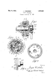
Further and more limited objects of the invention will appear as the description proceeds and by reference to the accompanying drawings in which Fig. 1 is a fragmentary sectional view on the line 11 of 2 and illustrating the preferred embodiment of my invention; Fig. 2 is a vertical sectional view on the line 22 of Fig. 1; Fig. 3 is a vertical sectional view on the line 33 of Fig. 1 and Fig. 4 is a detail view in side elevation of the operating handle.
Referring now to the drawings, the reference character 1 designates a shaft having a reduced end 2. Surrounding'the shaft 1 is a sleeve or casing 3 in which the shaft has a working fit. The sleeve or casing 3 has its outer end shaped to provide an annular recess 1. Fitting within the annular recess 4 is an annular member 5 which fits over the reduced end 2 of the shaft and is keyed thereto by a key 6. The annular member 5 is provided with a plurality of peripheral notches 7, 8 and 9 which are of the shape shown most clearly in Fig. 2. Arranged within each of the notches 7, 8 and 9 is a block 10 which is shaped as shown most clearly in Fig. 2. Also arranged within each of the notches 7, 8 and 9 are rollers 11 and 12 which engage respectively in recesses provided in the opposite ends of the block 10. Also disposed within each of the notches 7, 8 and 9 is an angular pawl 13 having a recess in the inner face thereof which forms a seat for the roller 11. The pawls 13 are consid- 18 and 19, respectively, which are normally urged outwardly by coil springs 20, 21 and 22. The thimbles bear against one end of the pawls and tend to pivot the pawls about the rollers, the purpose of which will hereinafter appear.
Fitting over the reduced end 2 of the shaft 1 is an annular cap 23 which has a working fit in the annular recess 4:. The cap 23 has a plurality of projections 24 thereon which project into the notches 7 8 and 9, respectively as shown most clearly in Fig. 2. A closure 25 closes the outer end of the annular recess 4 and is held thereon by screws 26. The closure 25 has a centrally disposed opening therein through which the reduced portion 23 of the cap 23 projects. The outerend of the reduced portion 23 is preferably hexagonal in shape and receives thereover an operating handle or lever 27 which is rigidly connected with the cap 23 by a plate 28 and screw 29.
The projections 24 are shaped in section as shown most clearly in Fig. 2 and are disposed within the notches 7, 8 and 9 so as to engage one end of the pawls 13 when the operating lever is rotated clockwise as seen in Fig. 2 and to engage the opposite walls of the notches when rotated in the opposite direction. From an inspection of Fig. 2, it will be seen that the rollers 11 and 12 are offset with respect to each other, that is, they are disposed along different radii.
It will therefore be seen that should the shaft 1 be turned clockwise independent of the operating handle, the pawls 13 and blocks 10 will produce a toggle action and lock the shaft against movement. However, should the operating lever be turned clockwise, the
projections 24.- will engage the pawls 13 and the aforementioned toggle action will not be obtained and the shaft may be freely rotated with respect to the sleeve. The springs 20, 21 and 22 normally urge the thimbles 17, 18 and 19 against the pawls 13 and maintain the same in position to produce the toggle action hereinbefore referred to, the shaft being free to rotate in the opposite direction. It is, of course, understood that the shaft may be rotated in either direction by means of the operating lever 27.
It will now be clear that I have provided a very simple and effective locking mechanism which will accomplish the objects of l the invent1on as hereinbefore stated.
Various changes may be made in details of construction as well as in the shape and arrange ment of the several parts without departing from the spirit of my invention and the ac companying drawings are merely illustrative and should not be considered in a limiting sense and my invention is limited only in accordance with the scope of the appended claims.
Having thus described my invention, what I claim is:
1. A locking mechanism for preventing movement between two relatively movable members including a sleeve adapted to be fixed with respect to one of said members, a generally circular disk non-rotatably secured to the other of said movable members, said disk being provided with a plurality of circumferential notches extending radially inwardly, bores in corresponding faces of said notches, thimbles in said bores, spring means urging said thimbles outwardly, an operating'member having projections thereon extend-ing into said notches. respectively, a friction block in each of said notches adapted to be engaged by one of said projections, said friction blocks and the inner ends of said notches each being provided with depressions for receiving bearing means, means cooperating with said depressions to provide with said disk and said friction blocks a locking mechanism for locking said sleeve and said disk against relative rotation in one direction, said friction blocks each being provided at one end with a lateral extension for cooperation with said thimble, said projections and said friction blocks having such dimensions circumferentially of said sleeve as to nearly but not com.- pletely fill said notches, said operating member serving to render said locking mechanism ineffective.
2., A locking mechanism including a casing having an annular recess, an annular member rotatable in said recess and having a notch therein transversely thereof, a pawl within said notch and radially against, the
circular wall of said recess, a roller in the-- bottom of said notch and longitudinally partly embedded therein, a roller against the inner face of said pawl and longitudinally partly embedded therein, a block in said notch and having said rollers longitudinally partly embedded in the ends thereof, the axes of said rollers being normally located on different radii of the mechanism, and a spring in said annular member normally tending to move said pawl along said circular wall tending to move the axis of said roller in the pawl toward the radial axis on which said roller in the notch is located to retainsaid pawl against said circular wall.
3. A locking mechanism including a casing having an annular recess, an annular member rotatable in said recess and having a notch the-rein transversely thereof, a pawl within said notch and radially against the circular wall of said recess, a'roller in the bottom of said notch and longitudinally partly embedded therein, a roller against the inner face of said pawl and longitudinally partly embedded therein, a block in said notch and having said rollers longitudinally partly embedded in the ends thereof, the axes of said rollers being normally located on different radii of the mechanism, a spring in said annular member normally tending to move said pawl along said circular wall tending to move the axis of said roller in the pawl toward the radial axis on which said roller in the notch is located to retain said pawl against said circular wall, and a cap rotatable in said annular recess and having an extension thereon reaching into said notch and upon a rotative movement thereof, adapted to move said pawl against compression in said spring to release said pawl from said circular wall.
4. A locking mechanism including a casing having an annular recess, an annular member rotatable in said recess and having a notch therein transversely thereof,-a pawl within said notch and radially against the circular wall of said recess, a roller in the bottom of said notch and longitudinally partly embedded therein, a roller against the inner face of said pawl and longitudinally partly embedded therein, a block in said notch and having said rollers longitudinally partly embedded in the ends thereof, the axes of said rollers being normally located on different radii of the mechanism, a spring in said annular member normally tending to move saidpawl along said circular wall tending. to move the axis of said roller in the pawl toward the; radial axis on which said roller in the notch: is located to retain said pawl against said circular wall, and a cap rotatable in said annular recess and having an extension thereon reaching into said notch and, upon a rotative movement thereof in one direction, adapted to contact a wall of said notch and, upon a rotative movement thereof in the other direction, adapted to move said pawl against compression in said spring to release said pawl from said circu lar wall.
In testimony whereof I hereunto afiix my signature.
JOSEPH VERDERBER.
Priority Applications (1)
| Application Number | Priority Date | Filing Date | Title |
|---|---|---|---|
| US301191A US1858065A (en) | 1928-08-22 | 1928-08-22 | Locking mechanism |
Applications Claiming Priority (1)
| Application Number | Priority Date | Filing Date | Title |
|---|---|---|---|
| US301191A US1858065A (en) | 1928-08-22 | 1928-08-22 | Locking mechanism |
Publications (1)
| Publication Number | Publication Date |
|---|---|
| US1858065A true US1858065A (en) | 1932-05-10 |
Family
ID=23162336
Family Applications (1)
| Application Number | Title | Priority Date | Filing Date |
|---|---|---|---|
| US301191A Expired - Lifetime US1858065A (en) | 1928-08-22 | 1928-08-22 | Locking mechanism |
Country Status (1)
| Country | Link |
|---|---|
| US (1) | US1858065A (en) |
Cited By (4)
| Publication number | Priority date | Publication date | Assignee | Title |
|---|---|---|---|---|
| US2493272A (en) * | 1944-05-18 | 1950-01-03 | Automatic Locking Devices Inc | Instrument control |
| US3043552A (en) * | 1960-03-03 | 1962-07-10 | Gen Motors Corp | Power transmitting mechanism for vehicle seats |
| WO2002084133A3 (en) * | 2001-04-17 | 2003-05-01 | Stoneridge Control Devices Inc | Electro-mechanical actuator and clutch for the same |
| US20050050976A1 (en) * | 2001-04-17 | 2005-03-10 | Knight Ko | Window lift system and actuator including an internal drive train disconnect |
-
1928
- 1928-08-22 US US301191A patent/US1858065A/en not_active Expired - Lifetime
Cited By (6)
| Publication number | Priority date | Publication date | Assignee | Title |
|---|---|---|---|---|
| US2493272A (en) * | 1944-05-18 | 1950-01-03 | Automatic Locking Devices Inc | Instrument control |
| US3043552A (en) * | 1960-03-03 | 1962-07-10 | Gen Motors Corp | Power transmitting mechanism for vehicle seats |
| WO2002084133A3 (en) * | 2001-04-17 | 2003-05-01 | Stoneridge Control Devices Inc | Electro-mechanical actuator and clutch for the same |
| US6557688B2 (en) * | 2001-04-17 | 2003-05-06 | Stoneridge Control Devices, Inc. | Electro-mechanical actuator and clutch for the same |
| US20050050976A1 (en) * | 2001-04-17 | 2005-03-10 | Knight Ko | Window lift system and actuator including an internal drive train disconnect |
| US8191442B2 (en) | 2001-04-17 | 2012-06-05 | Stoneridge Control Devices, Inc. | Window lift system and actuator including an internal drive train disconnect |
Similar Documents
| Publication | Publication Date | Title |
|---|---|---|
| GB2531900A (en) | Lock cylinder mechanism capable of preventing violent damage | |
| US1858065A (en) | Locking mechanism | |
| US2702468A (en) | Dust cover for locks | |
| US1858066A (en) | Locking mechanism | |
| US3606422A (en) | Lock assembly | |
| JP2009019726A (en) | Clutch mechanism with torque limiter | |
| US2034746A (en) | Automobile door handle | |
| US1002875A (en) | Swivel. | |
| US2202497A (en) | Overload release mechanism | |
| GB2494620A (en) | Thumb turn mechanism for a cylinder lock | |
| US1410033A (en) | Combination lock | |
| US1929235A (en) | Lock | |
| CN107401338B (en) | Back door locks provided on the back doors of vehicles and vehicles having the same | |
| US1982886A (en) | Driving-locking-releasing means | |
| JP4462879B2 (en) | Clutch mechanism | |
| US2288955A (en) | Operating knob or handle for shafts and the like | |
| US1376256A (en) | Lock | |
| JP5778627B2 (en) | Rotary switch device | |
| US2430391A (en) | Lock | |
| US1555229A (en) | Combination lock or padlock | |
| US2648557A (en) | Spring retainer ring | |
| US2302654A (en) | Bicycle lock | |
| US1783971A (en) | Lock | |
| US1082906A (en) | Lock for automobiles and the like. | |
| US1107588A (en) | Clutch. |