US1858064A - Rack - Google Patents
Rack Download PDFInfo
- Publication number
- US1858064A US1858064A US372303A US37230329A US1858064A US 1858064 A US1858064 A US 1858064A US 372303 A US372303 A US 372303A US 37230329 A US37230329 A US 37230329A US 1858064 A US1858064 A US 1858064A
- Authority
- US
- United States
- Prior art keywords
- shelf
- shelves
- drawer
- drawers
- rack
- Prior art date
- Legal status (The legal status is an assumption and is not a legal conclusion. Google has not performed a legal analysis and makes no representation as to the accuracy of the status listed.)
- Expired - Lifetime
Links
- 239000002184 metal Substances 0.000 description 4
- 230000003405 preventing effect Effects 0.000 description 3
- 239000005441 aurora Substances 0.000 description 2
- 238000010276 construction Methods 0.000 description 2
- 230000003014 reinforcing effect Effects 0.000 description 2
- 239000000047 product Substances 0.000 description 1
- 239000004576 sand Substances 0.000 description 1
Images
Classifications
-
- A—HUMAN NECESSITIES
- A47—FURNITURE; DOMESTIC ARTICLES OR APPLIANCES; COFFEE MILLS; SPICE MILLS; SUCTION CLEANERS IN GENERAL
- A47B—TABLES; DESKS; OFFICE FURNITURE; CABINETS; DRAWERS; GENERAL DETAILS OF FURNITURE
- A47B47/00—Cabinets, racks or shelf units, characterised by features related to dismountability or building-up from elements
- A47B47/02—Cabinets, racks or shelf units, characterised by features related to dismountability or building-up from elements made of metal only
- A47B47/021—Racks or shelf units
- A47B47/025—Racks or shelf units with panels connected together without three dimensional frames
Definitions
- This invention relates in general to metal shelving, and particularly though not ex clusively to a shelf rack for supporting shelf boxes or drawers.
- the primary object of the invention is to provide metal shelving for supporting shelf drawers, which shelving has means for pre venting the drawers from being accidentally withdrawn from the shelving and consequent "sp-illi'ng of contents.
- Another ob ect is to provide means on a drawer shelf which is engageable with the inner sides of the front and back of a drawer 1
- Another object is to provide a drawer shelf which has parts struck out therefrom extending below the shelf and engageable with a drawer thereon to limit the sliding movement of the drawer.
- the invention comprises in general a main shelf assembly which provides a housing for an auxiliary shelf rack.
- a plurality ofup rights are provided which receive shelf bearei-s.
- Shelves are arranged on these bearers which support a plurality of shelves spaced in tiers.
- a clip is fastened to an inturned ed e of the shelf, or a loop is struck out from .t e vshelf which engages the inner side of a drawer front and back to limit the sliding movement of the drawers.
- Fig. 1 is a fragmentary section taken from the front to rear of a shelf assembly, showing a drawer positioned beneath the top shelf and part of a drawer positioned directly below, and the structures for preventing complete withdrawal of each drawer.
- Fig. QJ- is a front elevation showing the structure employed for preventing complete withdrawal of the top drawer.
- FIG. 1 is a front elevation showing the to limit the sliding movement of the drawer.
- a main shelf assembly provides a housing for' an auxiliary shelf rack, and the main shelf assembly comprises a plurality of spaced front and rear tubular uprights 11. Each pair of uprights are connected by a vertical front to rear side wall 12'. A rear wall 13 is arranged between a pair of rear uprights 11,
- Main shelves 16 extend between adjacent supports and are supported at the front and rear by the shelf bearers 14.
- the slots 15 are elongated asshown' in Fig. 1 and arefor'med the opposed faces of the tubular uprights ll andengage the bearers in locked position.
- the main shelves 16 also may be bent at their side edges to form depending side flanges 23 which may be secured by bolts and nuts 24 to the sidewalls 12.
- the rear wall 13 may be secured in place by angular bracing members 25 which are bolted at 26 to the under surface of the main shelves 16. These braces extend downwardly be-- neath the rear bearers 14 and project through suitable slots in the rear wall 13 in hooked relation.
- the space between any pair .of superimposed shelves 16 and opposing side" walls 12 is employed for housing an auxiliary shelf rack.
- This auxiliary shelf rack comprises a plurality of front to rear up"- right panels 27, front and rear shelf bearers 28, and drawer shelves 29.
- the drawer a5 and front and rear shelf bearers Mare sup'- shelves 29 are supported on corresponding front and rear bearers 28.
- a front and rear series of T-shaped slots 30 are formed in the opposin upright panels 27 which are positioned iorizontally between the uprights.
- the slots 30 have a narrow or locking portion 31 which is disposed forwardly in the panel.
- the shelves may be adjusted to receive a drawer of any desired height by engaging the front and rear bearers 28 in appropriate slot-s 31.
- each drawer shelf 29 are bent at 32 to form depending flanges 33 which engage the outerfaces 'of the shelf bearers 28.
- the flanges 33 are bent at 34 to form inwardly extending horizontal flanges 35 which engage the bottom faces of the bearers 28.
- the front horizontal flange 35 is somewhat wider than the rear horizontal flange for a purpose of providing stops which will later be described.
- Drawers 36 are supported upon the shelves 16 and 29 and may be of any preferred construction. Accidental withdrawal of the lower drawers from their shelves is prevented by means of one or more depending loops 37 which are punched or pressed from the front horizontal flanges 35.
- the loops 37 are adapted to engage the rear wall 38 of a drawer 36 which is positioned on the shelf below. The loops also engage the front wall 39 of the drawer to limit its'inward movement.
- a drawer stop 40 which is formed of a metal plate 41 and bent at 42 to form an inwardly extending horizontal flange 43.
- This flange 43 is bent downwardly at 44 into a depend-' ing flange 45 which is adapted to engage the inside of the rear wall 38 of the shelf drawer 36.
- the flange 45 also engages the inside of the front wall of the drawer to limit its inward movement.
- the drawer stop 40 is positioned within the front flange of the shelf 16 so that the flange 43 will rest upon the flange 22.
- the flange 43 extends slightly beyond the flange .22 where it is bent downwardly to form the flange 45.
- the drawer stop 40 is securely fastened within the main shelf'flanging 20 by means of bolts and nuts 46 which pass through cooperating holes 47 in the shelf flanging and drawer stop. It will be understood, however, that other suitable fastening means may be employed.
- the invention provides a structure having adjustable shelf bearers which are supported in slots in the uprights. Shelves are carried by the bearers and they have parts arranged thereon or struck therefrom to form stops, which limit the sliding movement of the drawers.
- the stops may be quickly and readily made and promise a rigid and inexpensive means for limiting the movement of the drawers.
- a main shelf structure comprising tubular uprights, shelves supported by said uprights and provided at their front edges with depending horizontally extending flanges bent at their bot tom edges to providereturn flanges projecting inwardly of the shelf structure, a rack housed within said shelf structure, drawers mounted in said rack, and a drawer stop secured within the front flanges of said shelves and provided with a dependingoportion engageable with a drawer to limit the opening and closing movement of said drawer.
- a main shelf structure comprising tubular uprights; shelves supported by said uprights and providedat their front edges with depending horizontally extending reinforcing flanges bent at their bottom edges to provide return flanges proj ecting inwardly of the shelf structure, a-rack housed within said shelf structure and comprising a plurality of vertical uprights and a vertical series of shelf members mounted between said uprights, drawers supported on the uppermost shelf members of-said series of shelf members, and a drawer stop secured within the front flanges of said shelves and provided with a depending portion engageable with the top of a drawer to limit its opening and closing movement.
- a shelf structure comprising tubular uprights and a vertical series of shelves mounted between said uprights and provided at their front edges with depending horizontally extending reinforcing flanges bent at their bottom edges to provide return flanges projecting inwardly of the shelf rack, drawers supported on said shelves, and means p0- sitioned within the front flanges of said shelves for limiting the opening and closing movement of said drawers.
- a rack comprising front and rear supports, cross bearers connecting said supports, shelves supported by said cross bearers. drawers on said shelves, shelf bearers arranged between said upright-sand between a shelf and a drawer, shelves supported by said last named shelf bearers, drawers slidably mounted on said last named shelves, means on said first named shelves for limiting the sliding movement of said first named drawers. and loops struck out from the last named shelves for limiting the sliding movement of the last named drawers.
- a rack comprising spaced main shelves, auxiliary shelves arranged between the main shelves, drawers slidably mounted on said main and auxiliary shelves, removable means depending from the forward edges of the main shelves for limiting the sliding movement of the drawers on a lower auxiliary shelf, and means struck from the auxiliary shelves and integral therewith for limiting the sliding movement of a drawer arranged below said auxiliary shelf.
- a rack comprising supporting members, main shelves removably carried by said supporting members, auxiliary shelves removably positioned between the main shelves, drawers slidably mounted on all of said shelves, means removably carried atthe forward edge of said main shelves and depending therebelow for limiting the slidable movement of the drawers mounted on an auxiliary shelf. and loops struck out from an auxiliary shelf and near the forward end thereof for limiting the slidable movement of a drawer mounted below said auxiliary shelf.
Landscapes
- Assembled Shelves (AREA)
Description
2 Sheets-Sheet 1 W. N. VANCE RACK Filed June 20. 1929 May 10, 1932.
y 1932? w. N. VANCE 1,858,064
RACK
Eiled June 20, 1929 2 Sheets-Sheet 2 m Fig. 3
Patented May 10, 1932 i UNITED STATES PATENT OFFICE I @WALTER N. VANCE, OF NORTH AURORA, ILLINOIS, ASSIGNOB TO LYON METAL PROD- -UCTS', INCORPORATED; 0F AURORA, ILLINOIS, A CORPORATION OF ILLINOIS RACK Application filed June 20;
This invention relates in general to metal shelving, and particularly though not ex clusively to a shelf rack for supporting shelf boxes or drawers.
The primary object of the invention is to provide metal shelving for supporting shelf drawers, which shelving has means for pre venting the drawers from being accidentally withdrawn from the shelving and consequent "sp-illi'ng of contents.
Another ob ect is to provide means on a drawer shelf which is engageable with the inner sides of the front and back of a drawer 1 Another object is to provide a drawer shelf which has parts struck out therefrom extending below the shelf and engageable with a drawer thereon to limit the sliding movement of the drawer.
' Numerous other objects and advantages of the invention will be apparent as it is better understood from the following description,
which, taken in connection with the accoman'in drawin s. discloses a preferred emb b n 'bodii'nent thereof.
The invention comprises in general a main shelf assembly which provides a housing for an auxiliary shelf rack. A plurality ofup rights are provided which receive shelf bearei-s. Shelves are arranged on these bearers which support a plurality of shelves spaced in tiers. A clip is fastened to an inturned ed e of the shelf, or a loop is struck out from .t e vshelf which engages the inner side of a drawer front and back to limit the sliding movement of the drawers.
T he accompanying drawings illustrative a selpcted embodiment'of the invcntionand the views therein are as follows: 4
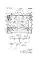
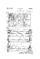
Fig. 1 is a fragmentary section taken from the front to rear of a shelf assembly, showing a drawer positioned beneath the top shelf and part of a drawer positioned directly below, and the structures for preventing complete withdrawal of each drawer.
Fig. QJ-is a front elevation showing the structure employed for preventing complete withdrawal of the top drawer.
is a front elevation showing the to limit the sliding movement of the drawer.
1929'. Serial No. 372,303,
This application is a c'o'nti'ni'i'ation in part of applicants' Patent No. 1,745,518.
A main shelf assembly provides a housing for' an auxiliary shelf rack, and the main shelf assembly comprises a plurality of spaced front and rear tubular uprights 11. Each pair of uprights are connected by a vertical front to rear side wall 12'. A rear wall 13 is arranged between a pair of rear uprights 11,
ported in slots 15 in the uprights. Main shelves 16 extend between adjacent supports and are supported at the front and rear by the shelf bearers 14. The slots 15 are elongated asshown' in Fig. 1 and arefor'med the opposed faces of the tubular uprights ll andengage the bearers in locked position. By engaging the bearers 14 in appropriate slots, the shelves may be positioned at any de= sired height depending upon the number and 7 bearers 14.- The main shelves 16 also may be bent at their side edges to form depending side flanges 23 which may be secured by bolts and nuts 24 to the sidewalls 12.
The rear wall 13 may be secured in place by angular bracing members 25 which are bolted at 26 to the under surface of the main shelves 16. These braces extend downwardly be-- neath the rear bearers 14 and project through suitable slots in the rear wall 13 in hooked relation. The space between any pair .of superimposed shelves 16 and opposing side" walls 12 is employed for housing an auxiliary shelf rack. This auxiliary shelf rack comprises a plurality of front to rear up"- right panels 27, front and rear shelf bearers 28, and drawer shelves 29. The drawer a5 and front and rear shelf bearers Mare sup'- shelves 29 are supported on corresponding front and rear bearers 28. A front and rear series of T-shaped slots 30 are formed in the opposin upright panels 27 which are positioned iorizontally between the uprights. The slots 30 have a narrow or locking portion 31 which is disposed forwardly in the panel.
It will be manifest that the shelves may be adjusted to receive a drawer of any desired height by engaging the front and rear bearers 28 in appropriate slot-s 31. The
front and rear edges of each drawer shelf 29 are bent at 32 to form depending flanges 33 which engage the outerfaces 'of the shelf bearers 28. The flanges 33 are bent at 34 to form inwardly extending horizontal flanges 35 which engage the bottom faces of the bearers 28. The front horizontal flange 35 is somewhat wider than the rear horizontal flange for a purpose of providing stops which will later be described.
In the present invention, accidental withdrawal of the top drawer 36 is prevented by a drawer stop 40 which is formed of a metal plate 41 and bent at 42 to form an inwardly extending horizontal flange 43. .This flange 43 is bent downwardly at 44 into a depend-' ing flange 45 which is adapted to engage the inside of the rear wall 38 of the shelf drawer 36. The flange 45 also engages the inside of the front wall of the drawer to limit its inward movement.
When it is desired to withdraw the drawer completely from the rack, it is drawn forwardly until the stop 40 engages the rear wall of the drawer, whereupon the front end of' the drawer is lifted until its lower rear edge is clear of the front edge of the drawer shelf 29. The rear of the boxmay then be lowered and disengaged from behind the stop 40.
The drawer stop 40 is positioned within the front flange of the shelf 16 so that the flange 43 will rest upon the flange 22. The flange 43 extends slightly beyond the flange .22 where it is bent downwardly to form the flange 45. The drawer stop 40 is securely fastened within the main shelf'flanging 20 by means of bolts and nuts 46 which pass through cooperating holes 47 in the shelf flanging and drawer stop. It will be understood, however, that other suitable fastening means may be employed.
The invention provides a structure having adjustable shelf bearers which are supported in slots in the uprights. Shelves are carried by the bearers and they have parts arranged thereon or struck therefrom to form stops, which limit the sliding movement of the drawers. The stops may be quickly and readily made and promise a rigid and inexpensive means for limiting the movement of the drawers.
1 Changes may be made in theform, construction, and arrangement of the parts without departing from the spirit of the invention or sacrificing any of the advantages thereof, and the right is hereby reserved to make all such changes as fairly fall within the scope of the following claims.
The invention is hereby claimed as follows:
1. The combination of a main shelf structure, comprising tubular uprights, shelves supported by said uprights and provided at their front edges with depending horizontally extending flanges bent at their bot tom edges to providereturn flanges projecting inwardly of the shelf structure, a rack housed within said shelf structure, drawers mounted in said rack, and a drawer stop secured within the front flanges of said shelves and provided with a dependingoportion engageable with a drawer to limit the opening and closing movement of said drawer.
2. The combination of a main shelf structure, comprising tubular uprights; shelves supported by said uprights and providedat their front edges with depending horizontally extending reinforcing flanges bent at their bottom edges to provide return flanges proj ecting inwardly of the shelf structure, a-rack housed within said shelf structure and comprising a plurality of vertical uprights and a vertical series of shelf members mounted between said uprights, drawers supported on the uppermost shelf members of-said series of shelf members, and a drawer stop secured within the front flanges of said shelves and provided with a depending portion engageable with the top of a drawer to limit its opening and closing movement.
3. A shelf structure comprising tubular uprights and a vertical series of shelves mounted between said uprights and provided at their front edges with depending horizontally extending reinforcing flanges bent at their bottom edges to provide return flanges projecting inwardly of the shelf rack, drawers supported on said shelves, and means p0- sitioned within the front flanges of said shelves for limiting the opening and closing movement of said drawers.
4. In combination, a rack comprising front and rear supports, cross bearers connecting said supports, shelves supported by said cross bearers. drawers on said shelves, shelf bearers arranged between said upright-sand between a shelf and a drawer, shelves supported by said last named shelf bearers, drawers slidably mounted on said last named shelves, means on said first named shelves for limiting the sliding movement of said first named drawers. and loops struck out from the last named shelves for limiting the sliding movement of the last named drawers.
5. The combination of a rack comprising spaced main shelves, auxiliary shelves arranged between the main shelves, drawers slidably mounted on said main and auxiliary shelves, removable means depending from the forward edges of the main shelves for limiting the sliding movement of the drawers on a lower auxiliary shelf, and means struck from the auxiliary shelves and integral therewith for limiting the sliding movement of a drawer arranged below said auxiliary shelf. 6. The combination of a rack comprising supporting members, main shelves removably carried by said supporting members, auxiliary shelves removably positioned between the main shelves, drawers slidably mounted on all of said shelves, means removably carried atthe forward edge of said main shelves and depending therebelow for limiting the slidable movement of the drawers mounted on an auxiliary shelf. and loops struck out from an auxiliary shelf and near the forward end thereof for limiting the slidable movement of a drawer mounted below said auxiliary shelf.
In witness whereof, I have hereunto subscribed my name. WALTER'N. VANCE.
Priority Applications (1)
| Application Number | Priority Date | Filing Date | Title |
|---|---|---|---|
| US372303A US1858064A (en) | 1929-06-20 | 1929-06-20 | Rack |
Applications Claiming Priority (1)
| Application Number | Priority Date | Filing Date | Title |
|---|---|---|---|
| US372303A US1858064A (en) | 1929-06-20 | 1929-06-20 | Rack |
Publications (1)
| Publication Number | Publication Date |
|---|---|
| US1858064A true US1858064A (en) | 1932-05-10 |
Family
ID=23467579
Family Applications (1)
| Application Number | Title | Priority Date | Filing Date |
|---|---|---|---|
| US372303A Expired - Lifetime US1858064A (en) | 1929-06-20 | 1929-06-20 | Rack |
Country Status (1)
| Country | Link |
|---|---|
| US (1) | US1858064A (en) |
Cited By (3)
| Publication number | Priority date | Publication date | Assignee | Title |
|---|---|---|---|---|
| US2599240A (en) * | 1948-08-24 | 1952-06-03 | Advertising Metal Display Co | Cabinet and drawer assembly |
| US2676080A (en) * | 1950-11-16 | 1954-04-20 | Convoy Inc | Filing cabinet shell |
| US3687091A (en) * | 1970-01-09 | 1972-08-29 | Norcross Inc | Display rack |
-
1929
- 1929-06-20 US US372303A patent/US1858064A/en not_active Expired - Lifetime
Cited By (3)
| Publication number | Priority date | Publication date | Assignee | Title |
|---|---|---|---|---|
| US2599240A (en) * | 1948-08-24 | 1952-06-03 | Advertising Metal Display Co | Cabinet and drawer assembly |
| US2676080A (en) * | 1950-11-16 | 1954-04-20 | Convoy Inc | Filing cabinet shell |
| US3687091A (en) * | 1970-01-09 | 1972-08-29 | Norcross Inc | Display rack |
Similar Documents
| Publication | Publication Date | Title |
|---|---|---|
| US1952111A (en) | Shelving construction | |
| US3168365A (en) | Cabinet structure with shelf attaching and supporting means | |
| US3067882A (en) | Suspension framework | |
| US3404931A (en) | Cabinet structure | |
| US3602159A (en) | Display rack | |
| US2900085A (en) | Adjustable shelf rack and reversible bracket therefor | |
| GB1019139A (en) | Storage rack | |
| US4219247A (en) | Suspended filing drawer | |
| US1716964A (en) | Display rack | |
| US3208807A (en) | Storage cabinet | |
| US1954384A (en) | Range | |
| US2098198A (en) | Sliding shelf | |
| US1772438A (en) | Office accessory | |
| US1858064A (en) | Rack | |
| US1878072A (en) | Display counter | |
| US1770500A (en) | Metal-table construction | |
| US1820716A (en) | Rack | |
| US1052516A (en) | Means for adjustably supporting shelves, partitions, and the like. | |
| US1798182A (en) | Boltless structure | |
| US2374658A (en) | Shelf construction | |
| US2896794A (en) | Metal shelving | |
| US1750696A (en) | Sheet-metal rack | |
| US2339339A (en) | Steel cabinet construction | |
| US3862789A (en) | Suspended pedestal desk | |
| US3199821A (en) | Shelf bracket |