US1858061A - Evaporator - Google Patents
Evaporator Download PDFInfo
- Publication number
- US1858061A US1858061A US360965A US36096529A US1858061A US 1858061 A US1858061 A US 1858061A US 360965 A US360965 A US 360965A US 36096529 A US36096529 A US 36096529A US 1858061 A US1858061 A US 1858061A
- Authority
- US
- United States
- Prior art keywords
- troughs
- wall
- trough
- liquid
- walls
- Prior art date
- Legal status (The legal status is an assumption and is not a legal conclusion. Google has not performed a legal analysis and makes no representation as to the accuracy of the status listed.)
- Expired - Lifetime
Links
- 239000007788 liquid Substances 0.000 description 35
- 238000010438 heat treatment Methods 0.000 description 14
- XLYOFNOQVPJJNP-UHFFFAOYSA-N water Substances O XLYOFNOQVPJJNP-UHFFFAOYSA-N 0.000 description 10
- 238000001704 evaporation Methods 0.000 description 5
- 239000002184 metal Substances 0.000 description 4
- 230000008020 evaporation Effects 0.000 description 2
- 230000003750 conditioning effect Effects 0.000 description 1
- 230000005574 cross-species transmission Effects 0.000 description 1
- 239000012530 fluid Substances 0.000 description 1
- 235000019645 odor Nutrition 0.000 description 1
Images
Classifications
-
- F—MECHANICAL ENGINEERING; LIGHTING; HEATING; WEAPONS; BLASTING
- F24—HEATING; RANGES; VENTILATING
- F24F—AIR-CONDITIONING; AIR-HUMIDIFICATION; VENTILATION; USE OF AIR CURRENTS FOR SCREENING
- F24F6/00—Air-humidification, e.g. cooling by humidification
- F24F6/02—Air-humidification, e.g. cooling by humidification by evaporation of water in the air
- F24F6/04—Air-humidification, e.g. cooling by humidification by evaporation of water in the air using stationary unheated wet elements
-
- Y—GENERAL TAGGING OF NEW TECHNOLOGICAL DEVELOPMENTS; GENERAL TAGGING OF CROSS-SECTIONAL TECHNOLOGIES SPANNING OVER SEVERAL SECTIONS OF THE IPC; TECHNICAL SUBJECTS COVERED BY FORMER USPC CROSS-REFERENCE ART COLLECTIONS [XRACs] AND DIGESTS
- Y10—TECHNICAL SUBJECTS COVERED BY FORMER USPC
- Y10S—TECHNICAL SUBJECTS COVERED BY FORMER USPC CROSS-REFERENCE ART COLLECTIONS [XRACs] AND DIGESTS
- Y10S203/00—Distillation: processes, separatory
- Y10S203/18—Control
Definitions
- Figure 1 is a top plan view of this illustrative embodiment of my invention, while Figure 2 is a section taken on the line 22 of Figure 1.
- the outsidewall 16, the inside wall 17, and the top member 18, for'ming together the cover 15 for the steam chamber 12 may be integrally formed, and may be spun into the proper shape, or it mavbe cast in one piece.
- the evaporator 11 is designed tobe heated by stem introduced into the steam chamber 12 through a steaminlet duct 19 in the side wall 14 while an outlet duct 20 in the bottom member 13 provides a convenient outlet for the steam chamber 12.
- the evaporator 11 also may conveniently be used in connection with a hot air heating apparatus and when it is thus used the steam chamber 12 may be eliminated so that'the evaporator may be suitably heated by placing it directly on the hot air heating apparatus.
- the liquid chamber 27 defined by the circular top member 18 of the steam chamber 12 and the inside wall 17 is provided with an overflow duct 25 extending a short distance into the liquid'chamber 27 above the circular top member 18 thereby providing a means for carrying away any surplus liquid accumulating in the liquid chamber 2'? yet without draining the liquid chamber 27.
- liquid to be evaporated is introduced into the top trough 23 through theinlet duct 24 and such liquid will first fill such top trough '23 and then as additional liquid is introduced will spill over the edges of the trough 23 into the next succeeding troughs 22 below. These will in turn become filled and will overflow and this operation will be repeated until all the troughs 22 are filled and are overflowing.
- the troughs 22 On account of the pitch of the sloping walls 16 and 17 and the pitch of the fins 21 thereon the troughs 22 will provide evaporating troughs of considerable area and the combined evaporating areas of such troughs is substantially greater than the horizontal area subtended by the walls 16 and 17. It readily will be apparent that either the inside wall 17 or the outside wall 16 may be used independently under certain circumstances, also that the evaporator may be any shape, square, oval, rec-' tangular, straight, curved, or otherwise.
- An air moistening device for combined air heating and humidiiying "apparatus comprising a metal wall, means for applying heat to one taco of saidwall, the other face of said wall being exposed to atmospheric contact and formed with outwardly 'projectingfins, each of said fins having an upturned lip between which andthe face of said plate is defined a liquid trough which partially underlies the fin next above, each of said lips extending horizontally from one end'thereot to the other whereby liquid introduced into the top trough will fill such top trough and then overflow into the troughs below, means closing the ends of said troughs, and means for introducing water into the top trough.
- An air inoistening device for living and working rooms comprising: two upwardly converging intersecting walls; a series of fins disposed on each wall forming a series of troughs each positioned to underlie the trough next above, whereby liquid introduced into the top trough of each wall will fill such top trough and then overflow into the troughs below, and the liquid contained in said troughs is spread over areas totalling substantially greater than the combined horizontal areas subtended by both said walls; mean for introducing water into the such top trough of said walls and means for applying heat to the opposite faces of said walls.
- An air moistening device for living and working rooms comprising: two upwardly converging sloping walls; a series of fins disposed on each wall forming series of troughs, each positioned to underlie the trough next above, and a liquid conduit connecting the top troughs of said walls, whereby liquid introduced into said common top trough will fill said top trough and then overfiow into the troughs below, and the liquid contained in said troughs is spread over areas totalling substantially greater than the combined horizontal areas subtended by both said walls; means for introducing water into said common top trough and means for applying heat to the opposite faces of said walls.
- a combined air heater and air moistener for heating and conditioning the .air of living and working rooms comprising in combination a hollow metal element having a part of its external wall exposed to the :atmosphere in heat exchanging relation and having another part of its external wall provided with vertically spaced, horizontally extending, outwardly projecting fins, each of said fins having an upturned outer margin which.
- An evaporator comprising: two upwardly converging intersecting annular walls; a series of annular fins disposed on each annular wall forming a series of annular troughs each positioned to underlie the trough next above, whereby liquid introduced into the top trough of each annular wall will fill such top trough and then overflow into the troughs below, and the liquid contained in said troughs is spread over areas totalling substantially greater than the combined horizontal area subtended by both said walls; and means for introducing water into such top trough of said walls.
- a combined air heating'and air moistening device for living and working rooms comprising a chamberedmetal structure having an externally exposed portionfor transmitting heat to the atmosphere, and also having an upwardly facing slanting surface; a series of fins disposed on said slanting surface forming a series of troughs, each positioned to similarly underlie the trough next above, and disposed so that the top trough is common to both said walls, whereby liquid introduced into the top trough will fill said top trough and then overflow into the troughs below, and the liquid contained in said troughs is spread over areas totalling substantially greater than the combined horizontal areas subtended by said walls; means for introducing water into said common top trough, means for introducing a heating medium into the interior of said chambered structure.
- An air moistening device for air heating systems comprislng an upwardly and laterally facing sloping wall, a series of fins on said wall disposed at an angle to the horizontal substantially equal to the angle of said wall to the horizontal and forming a series of troughs each positioned to underlie the trough next above, whereby liquid introduced into the top trough will fill said top trough and then overflow into the troughs below, and the liquid contained in said troughs is spread over areas totalling substantially greater than the horizontal area subtended by said wall; means for introducing water into the top trough. and means for heating the face of said wall which is opposite said fins.
- An evaporator comprising: two upwardly converging intersecting annular walls; a series of annular fins on each annular wall, disposed at an angle to the horizontal substantially equal to the angle to the horizontal of that said wall, forming on each said wall a series of annular troughs each positioned to underlie the trough next above, whereby liquid introduced into the top trough of each annular wall will fill such top trough and then overflow into the troughs below, and the liquid contained in said troughs is spread over areas totalling substantially greater than the combined horizontal areas subtended by both said walls; and means for introducing liquid into such top trough of said walls.
- An air moistening device for combined air heating and humidifying apparatus comprising a metal wall, means for applying heat to one face of said wall, the other face of said wall being exposed to atmospheric contact and formed with outwardly project ing fins, each of said fins having a marginal horizontal lip between which and the face of said plate is defined a liquid trough which partially underlies the trough next above and T trough will fill the same and then overflowinto the troughs below, and valved ductmeans communicating with the bottoms of said troughs whereby the liquid contents thereof can be evacuated promptly at any time.
- An air moistening device for combined air heating and humidifying apparatus comprising a metal wall, means for applying heat to one face of said wall, the other face of said wall being exposed to atmospheric contact and having thereon a plurality of horizontal troughs adapted for the reception'of water to be evaporated, and valved duct-means communicating with the bottoms of said troughs whereby the liquid contents thereof can be evacuated promptly at any time.
- An air moistening device comprising i in combination a plurality of horizontal troughs for the reception of water to be evaporated, means for supplying heat to said troughs, and valved duct-means communicating with the bottoms of said troughs whereby the liquid contents thereof can be evacuated promptly at any time.
Landscapes
- Engineering & Computer Science (AREA)
- Chemical & Material Sciences (AREA)
- Combustion & Propulsion (AREA)
- Mechanical Engineering (AREA)
- General Engineering & Computer Science (AREA)
- Air Humidification (AREA)
Description
J. ROEMER EVAPORATOR May 10, 1932.
Filed May 6, 1929 i 25 I K Patented May 10, 1932 D STATES PATENT VFFICE JULIUS ROEMER, 01? LAKEWOOD, OHIO EVAPORATOR Application filed May '6, 1929. Serial No. 360,965.
comparatively small space occupied so as to produce an adequate amount of evaporation at a comparatively low temperature thus enabling the requisite degree of air moistening without an undue amount of air heating or refiquiring an unduly high temperature of the heating appliance. Further objects and advantages of the invention will become ap parent as the description proceeds.
My tests have indicated that the timehonored custom of placing a jar of water on a steam radiator is little more than a gesture, since even a large tray does not give off sufficient vapor under some conditions. In addition the most successful heating systems are those in which radiators of considerable size are maintained at a rather moderate temperature, since all attempts to employ small radiators at high temperature are wasteful of heat and productive of unpleasant odors and 80 poor heat distribution. The amount of evaporation, however, depends both upon the temperature maintained and the liquid surface exposed and with any decrease of temperature an increase in the surface exposed becomes necessary. In the present application I have set forth one desirable mode of reconciling these two divergent requirements.
In the drawings accompanying this specification and forming a part of this application I have shown, for purposes of illustration, one form which my invention may assume, and in these drawings:
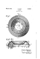
Figure 1 is a top plan view of this illustrative embodiment of my invention, while Figure 2 is a section taken on the line 22 of Figure 1.
The greatest efiiciency of an evaporator is attained by spreading the liquid to be evaporated over the greatest possible surface, 50 and in furtherance of this principle I have discovered that a sloping wall provided with a series of parallel fins providing horizon-V tallydisposed troughs, each adaptedto overlie the next succeeding one below, provides evaporating areas ,which in the aggregate areas are substantially greater than the hori-.
fore provides a simple and effective evaporaor.v 1
I show my invention as applied to an evaporator 11 having a steam chamber 12 comprising a flat circular bottom member 13 and a perpendicular side wall 14' arising from the outer periphery of the bottom member 13 and supporting on its upper edge a steam chamber cover 15 having a sloping circular outside wall 16 suitably mountedon the top edge of the outside wall 14 and sloping toward the centerfof the evaporator 11 at an angle of approximately to-the bottom member 13 of the steam chamber 12, while a corresponding circular sloping inside wall 17 joining the top periphery of the outside wall 16 at an angle of approximately 90 extends downwardly therefrom to a flat circular top member 18. I find that the outsidewall 16, the inside wall 17, and the top member 18, for'ming together the cover 15 for the steam chamber 12, may be integrally formed, and may be spun into the proper shape, or it mavbe cast in one piece.
The evaporator 11 is designed tobe heated by stem introduced into the steam chamber 12 through a steaminlet duct 19 in the side wall 14 while an outlet duct 20 in the bottom member 13 provides a convenient outlet for the steam chamber 12. The evaporator 11 also may conveniently be used in connection with a hot air heating apparatus and when it is thus used the steam chamber 12 may be eliminated so that'the evaporator may be suitably heated by placing it directly on the hot air heating apparatus.
A plurality of parallel fins 21, suitably se-' cured to the upper surfaces of the outside wall 16 and of the inside wall 17 and extending completely therearound, are positioned thereon at substantially an angle of 90 thereto and define horizontally disposed troughs 22 disposed one above the otherand 'zontal area subtended by said wall, and thereadapted to receive a liquid to be evaporated therein which may be introduced into a top trough 23' through an inlet duct 24. The liquid chamber 27 defined by the circular top member 18 of the steam chamber 12 and the inside wall 17 is provided with an overflow duct 25 extending a short distance into the liquid'chamber 27 above the circular top member 18 thereby providing a means for carrying away any surplus liquid accumulating in the liquid chamber 2'? yet without draining the liquid chamber 27.
In operation, liquid to be evaporated is introduced into the top trough 23 through theinlet duct 24 and such liquid will first fill such top trough '23 and then as additional liquid is introduced will spill over the edges of the trough 23 into the next succeeding troughs 22 below. These will in turn become filled and will overflow and this operation will be repeated until all the troughs 22 are filled and are overflowing. On account of the pitch of the sloping walls 16 and 17 and the pitch of the fins 21 thereon the troughs 22 will provide evaporating troughs of considerable area and the combined evaporating areas of such troughs is substantially greater than the horizontal area subtended by the walls 16 and 17. It readily will be apparent that either the inside wall 17 or the outside wall 16 may be used independently under certain circumstances, also that the evaporator may be any shape, square, oval, rec-' tangular, straight, curved, or otherwise.
The use of ducts 28 and valve means 29 connected to the bottoms of the different troughs serves to enable the evacuation of the liquid contents promptly at any time.
It will be apparent to those skilled in the art that the invention herein shown and described may be variously changed, modified, or used all without departing from the spirit of my invention or sacrificing the advantages thereof, and it therefore will be understood that the disclosure herein is illustrative only, and that my invention is not limited thereto.
1. An air moistening device for combined air heating and humidiiying "apparatus comprising a metal wall, means for applying heat to one taco of saidwall, the other face of said wall being exposed to atmospheric contact and formed with outwardly 'projectingfins, each of said fins having an upturned lip between which andthe face of said plate is defined a liquid trough which partially underlies the fin next above, each of said lips extending horizontally from one end'thereot to the other whereby liquid introduced into the top trough will fill such top trough and then overflow into the troughs below, means closing the ends of said troughs, and means for introducing water into the top trough.
An air inoistening device for living and working rooms comprising: two upwardly converging intersecting walls; a series of fins disposed on each wall forming a series of troughs each positioned to underlie the trough next above, whereby liquid introduced into the top trough of each wall will fill such top trough and then overflow into the troughs below, and the liquid contained in said troughs is spread over areas totalling substantially greater than the combined horizontal areas subtended by both said walls; mean for introducing water into the such top trough of said walls and means for applying heat to the opposite faces of said walls.
8. An air moistening device for living and working rooms comprising: two upwardly converging sloping walls; a series of fins disposed on each wall forming series of troughs, each positioned to underlie the trough next above, and a liquid conduit connecting the top troughs of said walls, whereby liquid introduced into said common top trough will fill said top trough and then overfiow into the troughs below, and the liquid contained in said troughs is spread over areas totalling substantially greater than the combined horizontal areas subtended by both said walls; means for introducing water into said common top trough and means for applying heat to the opposite faces of said walls. I
4. A combined air heater and air moistener for heating and conditioning the .air of living and working rooms comprising in combination a hollow metal element having a part of its external wall exposed to the :atmosphere in heat exchanging relation and having another part of its external wall provided with vertically spaced, horizontally extending, outwardly projecting fins, each of said fins having an upturned outer margin which. defines, with the adjacent face of said element, a liquid receiving trough which underlies in part the fin next in order above the same, whereby liquid introduced into the top trough will first fill such top trough and then overflow into the troughs below and the liquid contained in said troughs is spread over areas totalling substantially greater than the superficial area of that face of the element whereby said remains are carried: means for introducing water in such top trough and means for supplying heating fluid to the interior of said element.
5. An evaporator comprising: two upwardly converging intersecting annular walls; a series of annular fins disposed on each annular wall forming a series of annular troughs each positioned to underlie the trough next above, whereby liquid introduced into the top trough of each annular wall will fill such top trough and then overflow into the troughs below, and the liquid contained in said troughs is spread over areas totalling substantially greater than the combined horizontal area subtended by both said walls; and means for introducing water into such top trough of said walls.
6. A combined air heating'and air moistening device for living and working rooms comprising a chamberedmetal structure having an externally exposed portionfor transmitting heat to the atmosphere, and also having an upwardly facing slanting surface; a series of fins disposed on said slanting surface forming a series of troughs, each positioned to similarly underlie the trough next above, and disposed so that the top trough is common to both said walls, whereby liquid introduced into the top trough will fill said top trough and then overflow into the troughs below, and the liquid contained in said troughs is spread over areas totalling substantially greater than the combined horizontal areas subtended by said walls; means for introducing water into said common top trough, means for introducing a heating medium into the interior of said chambered structure.
7. An air moistening device for air heating systems comprislng an upwardly and laterally facing sloping wall, a series of fins on said wall disposed at an angle to the horizontal substantially equal to the angle of said wall to the horizontal and forming a series of troughs each positioned to underlie the trough next above, whereby liquid introduced into the top trough will fill said top trough and then overflow into the troughs below, and the liquid contained in said troughs is spread over areas totalling substantially greater than the horizontal area subtended by said wall; means for introducing water into the top trough. and means for heating the face of said wall which is opposite said fins.
8. An evaporator comprising: two upwardly converging intersecting annular walls; a series of annular fins on each annular wall, disposed at an angle to the horizontal substantially equal to the angle to the horizontal of that said wall, forming on each said wall a series of annular troughs each positioned to underlie the trough next above, whereby liquid introduced into the top trough of each annular wall will fill such top trough and then overflow into the troughs below, and the liquid contained in said troughs is spread over areas totalling substantially greater than the combined horizontal areas subtended by both said walls; and means for introducing liquid into such top trough of said walls.
9. An air moistening device for combined air heating and humidifying apparatus comprising a metal wall, means for applying heat to one face of said wall, the other face of said wall being exposed to atmospheric contact and formed with outwardly project ing fins, each of said fins having a marginal horizontal lip between which and the face of said plate is defined a liquid trough which partially underlies the trough next above and T trough will fill the same and then overflowinto the troughs below, and valved ductmeans communicating with the bottoms of said troughs whereby the liquid contents thereof can be evacuated promptly at any time.
10. An air moistening device for combined air heating and humidifying apparatus comprising a metal wall, means for applying heat to one face of said wall, the other face of said wall being exposed to atmospheric contact and having thereon a plurality of horizontal troughs adapted for the reception'of water to be evaporated, and valved duct-means communicating with the bottoms of said troughs whereby the liquid contents thereof can be evacuated promptly at any time.
11. An air moistening device comprising i in combination a plurality of horizontal troughs for the reception of water to be evaporated, means for supplying heat to said troughs, and valved duct-means communicating with the bottoms of said troughs whereby the liquid contents thereof can be evacuated promptly at any time.
In testimony whereof I hereunto aflix my signature.
JULIUS ROEMER.
Priority Applications (1)
| Application Number | Priority Date | Filing Date | Title |
|---|---|---|---|
| US360965A US1858061A (en) | 1929-05-06 | 1929-05-06 | Evaporator |
Applications Claiming Priority (1)
| Application Number | Priority Date | Filing Date | Title |
|---|---|---|---|
| US360965A US1858061A (en) | 1929-05-06 | 1929-05-06 | Evaporator |
Publications (1)
| Publication Number | Publication Date |
|---|---|
| US1858061A true US1858061A (en) | 1932-05-10 |
Family
ID=23420098
Family Applications (1)
| Application Number | Title | Priority Date | Filing Date |
|---|---|---|---|
| US360965A Expired - Lifetime US1858061A (en) | 1929-05-06 | 1929-05-06 | Evaporator |
Country Status (1)
| Country | Link |
|---|---|
| US (1) | US1858061A (en) |
-
1929
- 1929-05-06 US US360965A patent/US1858061A/en not_active Expired - Lifetime
Similar Documents
| Publication | Publication Date | Title |
|---|---|---|
| US1858061A (en) | Evaporator | |
| US2150514A (en) | Air conditioning apparatus | |
| CN208419037U (en) | The heat-exchanger rig of water distribution in managing | |
| US2161834A (en) | Air conditioning apparatus | |
| US2022394A (en) | Humidifier | |
| US1583255A (en) | Humidifying radiator | |
| US2365829A (en) | Humidifying apparatus | |
| CN111961567A (en) | High security just heats even making wine equipment | |
| US1943379A (en) | Humidifier | |
| US1872195A (en) | Air conditioning apparatus | |
| US2651293A (en) | Humidifier boiler | |
| US2124510A (en) | Humidifier | |
| US1995409A (en) | Humidifier | |
| US2323186A (en) | Refrigeration | |
| US1962180A (en) | Humidifying radiator | |
| US2069145A (en) | Liquid vaporizing and air humidifying apparatus | |
| US2144169A (en) | Method and apparatus for conditioning air | |
| KR790001612Y1 (en) | Indoor air heating | |
| US1337766A (en) | Air-moistener | |
| US1737008A (en) | Humidifier | |
| US20250043969A1 (en) | System and apparatus for humidifier on high-efficiency forced air Furnace and kit therefore | |
| KR20200048369A (en) | Cooling System with Cooling Chiller | |
| US1644737A (en) | Humidifier | |
| SU481755A1 (en) | Heating system | |
| US1094544A (en) | Humidifying device. |