US1858050A - Change speed gear set - Google Patents
Change speed gear set Download PDFInfo
- Publication number
- US1858050A US1858050A US524521A US52452131A US1858050A US 1858050 A US1858050 A US 1858050A US 524521 A US524521 A US 524521A US 52452131 A US52452131 A US 52452131A US 1858050 A US1858050 A US 1858050A
- Authority
- US
- United States
- Prior art keywords
- gear
- shaft
- gears
- rod
- gear set
- Prior art date
- Legal status (The legal status is an assumption and is not a legal conclusion. Google has not performed a legal analysis and makes no representation as to the accuracy of the status listed.)
- Expired - Lifetime
Links
- 230000005540 biological transmission Effects 0.000 description 7
- 230000007935 neutral effect Effects 0.000 description 7
- 230000033001 locomotion Effects 0.000 description 4
- 238000010276 construction Methods 0.000 description 2
- 241001052209 Cylinder Species 0.000 description 1
- 235000014443 Pyrus communis Nutrition 0.000 description 1
- 238000007792 addition Methods 0.000 description 1
- 230000000694 effects Effects 0.000 description 1
- 230000004048 modification Effects 0.000 description 1
- 238000012986 modification Methods 0.000 description 1
Images

Classifications
-
- F—MECHANICAL ENGINEERING; LIGHTING; HEATING; WEAPONS; BLASTING
- F16—ENGINEERING ELEMENTS AND UNITS; GENERAL MEASURES FOR PRODUCING AND MAINTAINING EFFECTIVE FUNCTIONING OF MACHINES OR INSTALLATIONS; THERMAL INSULATION IN GENERAL
- F16H—GEARING
- F16H63/00—Control outputs from the control unit to change-speed- or reversing-gearings for conveying rotary motion or to other devices than the final output mechanism
- F16H63/02—Final output mechanisms therefor; Actuating means for the final output mechanisms
- F16H63/30—Constructional features of the final output mechanisms
-
- F—MECHANICAL ENGINEERING; LIGHTING; HEATING; WEAPONS; BLASTING
- F16—ENGINEERING ELEMENTS AND UNITS; GENERAL MEASURES FOR PRODUCING AND MAINTAINING EFFECTIVE FUNCTIONING OF MACHINES OR INSTALLATIONS; THERMAL INSULATION IN GENERAL
- F16D—COUPLINGS FOR TRANSMITTING ROTATION; CLUTCHES; BRAKES
- F16D23/00—Details of mechanically-actuated clutches not specific for one distinct type
- F16D23/02—Arrangements for synchronisation, also for power-operated clutches
- F16D23/04—Arrangements for synchronisation, also for power-operated clutches with an additional friction clutch
-
- Y—GENERAL TAGGING OF NEW TECHNOLOGICAL DEVELOPMENTS; GENERAL TAGGING OF CROSS-SECTIONAL TECHNOLOGIES SPANNING OVER SEVERAL SECTIONS OF THE IPC; TECHNICAL SUBJECTS COVERED BY FORMER USPC CROSS-REFERENCE ART COLLECTIONS [XRACs] AND DIGESTS
- Y10—TECHNICAL SUBJECTS COVERED BY FORMER USPC
- Y10T—TECHNICAL SUBJECTS COVERED BY FORMER US CLASSIFICATION
- Y10T74/00—Machine element or mechanism
- Y10T74/19—Gearing
- Y10T74/19219—Interchangeably locked
- Y10T74/19284—Meshing assisters
Definitions
- Fig. 8 is a similar view .showing them enspeed gearing capable of general use but partirely in; ticularly adapted for use on automobiles.
- FIG. 12 is a side view of the direct connecrequire a considerable increase in the size tion clutch, partly in section showing it of the gear casing. Moreover, none of the shifted in part way, and present noiseless change gear devices provides Fig. 13 is a similar view showing it fully for synchronizing all speeds and reverse. connected.
- the principal objects of this invention are The invention is shown as applied to agear to provide a construction, involving few extransmission in general of the well known 60 tra and relatively small parts and thus catype. It involves the motor shaft 10 for oppable of being contained in a small compass, erating the drive shaft 11.
- the motor shaft which will provide a noiseless and easy shifthas a gear 12 which is always in mesh with ing of the gears of a change-speed gear transa gear 13 on a countersha'ft 14, which has in mission; to provide a device for accomplishthis case three gears 15, 16 and 17 fixed to it ing a similar purpose in connection with the and always running.
- the gear 15 meshes shifting to a direct connection between the with a gear 18 and the gear 16 with a gear driving and the driven shafts, to provide 19 and the gear 17 through a third or rethese features in a simple. inexpensive and versing gear with a gear 20, which, of course, convenient arrangement of parts easy to aswillreverse the rotation of the shaft 11.
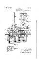
- Fig. 1 is a sectional view of a gear casing having internal projections 25 extending into showing a preferred embodiment of this inthe slots 21 and all these six gears are slidvention in partial elevation and in neutral able on this shaft.
- Fig. 2 is a sectional view on the line 22 cooperating conical surfaces 26, which are of Fig.
- Fig. 3 is a sectional view on the line 33 shown in Fig. 1.
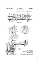
- Fig. 4 is a sectional view on the line H pear. of Fig.1, showing the shifting rods in plan;
- Fig. 5 is an end view of the outside of the which has auniversal support 31 to allow -1 top part of the casing; it to turn in two directions at right angles
- Fig. 6 is a sectional view on the line 6-6 to each other.
- Fig. 1 The lower end of it is adaptof Fig. 1; ed to engage in either one of two slots 32 and Fig. 7 is a view similar to Fig. 1 showing 83 in a pair of shifting slides 34. and 35, one the first set of gears partially shifted from mounted on each of two rods 36 and 37 which W neutral position, to throw them in; are arranged parallel with each other as usual 1 and are shiftable endwise.
- the front one of these rods 36 is provided with a split collar 38 fixed to it and having a yoke 39 and also a split collar 48 fixed to the rod.
- the shifting slide 34 is also provided with a yoke 40.
- the rear slide is provided with a bridge 41 which connects it with a slide-42 on the rod 37.
- This slide 42 is provided with a yoke 43.
- These "several yokes 39, 40, 43, 46 and 47 are all connected with the several collars 27 and therefore are adapted to shift the several gears in certain relationships.
- the split collars are all spaced from the slides 34 and 42 when the parts are in neutral position as shown in Fig. 1.
- each .pair of gears is provided its conical surface 26 with notches around the circumference. These notches are provided so that when the two conical surfaces of the gears of each pair come together any oil getting in between them will *be scraped off by the square '1 edges of these notches and prevent it from causing any restriction to the effectiveness of vtlieconeclntches.
- Each rod 36 and 37 is provided in-this'case with three V-rshape'd notches 49 and 50-.
- a'cylin-der 51 having a spring-pressed plunger 52 provided with :a Mshaped end to enter these notches.
- a screw 53 is arranged at the top of each cylinderfto hold the spring 54 and provide access to thefinterior.
- TihQiSCI'B-VV3H1SO . is ca :p'asble or adjusting the compressing of the spring.
- the center one of the notches49 5'0 is deeper than the others to afford more resistance when shifting from neutral into rear.
- the means for connecting the two shafts 1 01an d 11 directly to each other to give the highest :speed is the form of-a clutch having a similar construction.
- Integral-or Siixed member 610 of a clutch having-.teeth'61on its "edge. iFixed to or integral with the gear .22 is a male member 6.2 :of this clutch.
- This has teeth 63 projecting from its edge and "adapted, when the parts are -.cl-osecl together as shownin 13, to mesh therewith.
- This member 62 also "has radial recesses therein in which :are located loose "blocks 64, each one provided a tapered surface -65 which in the aggregate constitute an interrupted conical surface.
- Each one is provided with a stop end 66 projecting toward the shaft 10.
- ilteilso has :a recess 71 for receiving a plate 68.
- the female member 60 is provided with an internal conica'l surface 67 and a circular recess *69 enlarged at 70 beyond the surface-67.
- the member 62 is provided with an annular plate '68 which retains the blocks '64 Tn the operation of the device, starting from neutral position as shown in Fig. 1, if it is intended to start in reverse or low forward speed the shifting lever 30 is shifted so that the lower end will come into the notch 33 as shown in Fig. 4 and then it is moved from central position either to the front or back according to the desired direction of motion. In either case the gear 23 or .24, as the case may be, will be caused to move over toward its companion gear and the conical surfaces 26 are brought into contact.
- gear 22 will be withdrawn from all contact with the gear 18 so that the latter rotates idly on the shaft 11.
- a further movement in the same direction brings the teeth 61 and 63 into engagement with each other as shown in Fig. 13 and the two shafts are positively clutched together.
- the gears of the entire trans-mission can be accomplished without the clutching of gears in a very quick manner and also without the danger of knocking off the teeth or the corners of the teeth when the gear changes are made.
- the parts are durable and unlikely to get out of order and very little is added to the ordinary gear transmission so that the whole transmission will occupy little or any more space than it does without these additions. This reduces the space very materially, at least over the devices not on the market for reducing the noise of gear changes, and there are no conditions under which the operator has not full control of the drive.
- a transmission gear set the combination with a motor shaft, a driven shaft and a counter-shaft, of means by which the counter-shaft is driven constantly, from the driving shaft, a gear on the counter shaft, 21 pair of gears on the driven shaft, one normally meshing with the gear on the counter-shaft but freely rotatable on the driven shaft, the other located adjacent to the said gear on the driven shaft and slidably keyed thereto and normally out of mesh with the gear on the counter-shaft, said pair of gears having frictional surfaces on their adjacent sides adapted to come into contact with each other to drive the keyed gear from the loose gear by friction prior to the movement of the said rod having notches and a spring-pressed plunger normally engaging in one of said notches, whereby when the rod is pushed overthe plunger will be forced outwardly in the notch while the keyed gear'comes' i'ntofrictional contact with the conicalsurface on the loose gear, for the purposedescribed. 2-.
- a gear fixed on the counter-shaft a pair of gears, one slidablyakeyed andthe other loose on the drivenshaft having the same number ofteeth, either one adapted to mesh with'the gear on the counter-shaft and having frictional driving surfaces between them, whereby when'the loose gear is in mesh with the counter-shaft gear and the keyed gear is moved toward it,'the first effect will be to pick up the keyed gear and rotate it by friction from the loose gear
Landscapes
- Engineering & Computer Science (AREA)
- General Engineering & Computer Science (AREA)
- Mechanical Engineering (AREA)
- Structure Of Transmissions (AREA)
Description
May 10, 1932. LQMEBARD 1,858,050
CHANGE SPEED GEAR SET Filed March 23, 1931 4 Sheets Sheet 1 May 10, 932. K LOMBARD 1,858,050
CHANGE SPEED GEAR SET Filed March 23, 1931 4 Sheets-Sheet 2 y 1932- N. LOMBARD 1,858,050
CHANGE SPEED GEAR SET Filed March 23, 1951 4 Sheets-Sheet 3 1155.14 Mowe zzomzow AWM May 10, 1932. LQMBARD 1,858,050
CHANGE SPEED GEAR SET Filed March 23, 1931 4 Sheets-Sheet 4 Patented May 10, 1932 UNETED STATES PATENT GFFlCE NATHANIEL LOMBARD, OF WQRCESTER, MASSACHUSETTS CHANGE SPEED GEAR SET Application filed March 23, 1931; Serial No. 524,521.
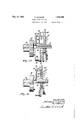
This invention relates to noiseless change Fig. 8 is a similar view .showing them enspeed gearing capable of general use but partirely in; ticularly adapted for use on automobiles. Fig. 9 is an end view of one member of the Heretofore many devices have been invented direct connection clutch; for the purpose of securing a more noiseless Fig. 10 is a sectional view on the broken shifting of gears than results in the usual line 10-10 of Fig. 9; form of gear transmission; but successful Fig. 11 is a side view of one of the loose ones have involved complicated and bulky blocks shown in Fig. 9; features which are difficult to assemble and Fig. 12 is a side view of the direct connecrequire a considerable increase in the size tion clutch, partly in section showing it of the gear casing. Moreover, none of the shifted in part way, and present noiseless change gear devices provides Fig. 13 is a similar view showing it fully for synchronizing all speeds and reverse. connected.
The principal objects of this invention are The invention is shown as applied to agear to provide a construction, involving few extransmission in general of the well known 60 tra and relatively small parts and thus catype. It involves the motor shaft 10 for oppable of being contained in a small compass, erating the drive shaft 11. The motor shaft which will provide a noiseless and easy shifthas a gear 12 which is always in mesh with ing of the gears of a change-speed gear transa gear 13 on a countersha'ft 14, which has in mission; to provide a device for accomplishthis case three gears 15, 16 and 17 fixed to it ing a similar purpose in connection with the and always running. The gear 15 meshes shifting to a direct connection between the with a gear 18 and the gear 16 with a gear driving and the driven shafts, to provide 19 and the gear 17 through a third or rethese features in a simple. inexpensive and versing gear with a gear 20, which, of course, convenient arrangement of parts easy to aswillreverse the rotation of the shaft 11. The
semble, and to enable its change-gear operator gears18, 19 and 20 are rotatably mounted on to synchronize each of all forward and rethe shaft 11 which throughout this series of verse speeds. gears is provided with longitudinal slots 21.
Other objects and advantages of the inven- Fixed to this slotted part of the shaft 11 s tion will appear hereinafter. are a series of gears 22, 23 and 24 cooperat- Reference is to be had to the accompanying ing with the gears 18, 19 and 20 respectively drawings, in which in pairs. They are fixed to this shaft 11 by Fig. 1 is a sectional view of a gear casing having internal projections 25 extending into showing a preferred embodiment of this inthe slots 21 and all these six gears are slidvention in partial elevation and in neutral able on this shaft. Each pair of gears as 18 position; i and 22, 19 and 23, 20 and 2 1 are provided with Fig. 2 is a sectional view on the line 22 cooperating conical surfaces 26, which are of Fig. 1; normally out of'contact with each other as Fig. 3 is a sectional view on the line 33 shown in Fig. 1. On all these gears are ciro of Fig. 1, showing one of the gears in elevacumferentially grooved collars 27 which can 0 tion; be operated by the several yokes as will ap- Fig. 4 is a sectional view on the line H pear. of Fig.1, showing the shifting rods in plan; The usual shifting lever 30 is employed, Fig. 5 is an end view of the outside of the which has auniversal support 31 to allow -1 top part of the casing; it to turn in two directions at right angles Fig. 6 is a sectional view on the line 6-6 to each other. The lower end of it is adaptof Fig. 1; ed to engage in either one of two slots 32 and Fig. 7 is a view similar to Fig. 1 showing 83 in a pair of shifting slides 34. and 35, one the first set of gears partially shifted from mounted on each of two rods 36 and 37 which W neutral position, to throw them in; are arranged parallel with each other as usual 1 and are shiftable endwise. The front one of these rods 36 is provided with a split collar 38 fixed to it and having a yoke 39 and also a split collar 48 fixed to the rod. The shifting slide 34 is also provided with a yoke 40. The rear slide is provided with a bridge 41 which connects it with a slide-42 on the rod 37. This slide 42 is provided with a yoke 43. On the rod 37 there are two split collars 44 and 45 fixed to it and provided with two yokes 46 and 47. These " several yokes 39, 40, 43, 46 and 47 are all connected with the several collars 27 and therefore are adapted to shift the several gears in certain relationships. The split collars are all spaced from the slides 34 and 42 when the parts are in neutral position as shown in Fig. 1.
' One of each .pair of gears,.as for example, 22, 23 and 24, is provided its conical surface 26 with notches around the circumference. These notches are provided so that when the two conical surfaces of the gears of each pair come together any oil getting in between them will *be scraped off by the square '1 edges of these notches and prevent it from causing any restriction to the effectiveness of vtlieconeclntches.
Each rod 36 and 37 is provided in-this'case with three V-rshape'd notches 49 and 50-. In cooperation with :each one is a'cylin-der 51 havinga spring-pressed plunger 52 provided with :a Mshaped end to enter these notches. A screw 53 is arranged at the top of each cylinderfto hold the spring 54 and provide access to thefinterior. TihQiSCI'B-VV3H1SO .is ca :p'asble or adjusting the compressing of the spring. The center one of the notches49 5'0 is deeper than the others to afford more resistance when shifting from neutral into rear.
The means for connecting the two shafts 1 01an d 11 directly to each other to give the highest :speed is the form of-a clutch having a similar construction. Integral-or Siixed member 610 of a clutch having-.teeth'61on its "edge. iFixed to or integral with the gear .22 is a male member 6.2 :of this clutch. This has teeth 63 projecting from its edge and "adapted, when the parts are -.cl-osecl together as shownin 13, to mesh therewith. This member 62 also "has radial recesses therein in which :are located loose "blocks 64, each one provided a tapered surface -65 which in the aggregate constitute an interrupted conical surface. Each one is provided with a stop end 66 projecting toward the shaft 10. ilteilso has :a recess 71 for receiving a plate 68. The female member 60 is provided with an internal conica'l surface 67 and a circular recess *69 enlarged at 70 beyond the surface-67. The member 62 is provided with an annular plate '68 which retains the blocks '64 Tn the operation of the device, starting from neutral position as shown in Fig. 1, if it is intended to start in reverse or low forward speed the shifting lever 30 is shifted so that the lower end will come into the notch 33 as shown in Fig. 4 and then it is moved from central position either to the front or back according to the desired direction of motion. In either case the gear 23 or .24, as the case may be, will be caused to move over toward its companion gear and the conical surfaces 26 are brought into contact.
It will be understood of course that the gears 19.and 20 as well as 18 are constantly running and therefore the gear 23 or 24 will he started up frictionally. It will soon get to the speed-of thegear 19 or 20-andalthough the teeth-of the two gears may not be in registration they will rotate at practically the same speed. The motion of the rod 37 brings its plunger 52 part way out of its notch as shown in Fig. 7 forexample and creates :a
resistance which is released as soon as the plunger is entirely out of the notch. This relieves the pressure on the conical surfaces 26 allowing a little slip between the two gears which will bring the teeth of the two gears of the pair into registration. Then the further shifting of the rod will slide the gears togethenas will be seen readily. Thus the gears 16 and 23 or 17 and 24 will be in mesh at their edges and as the rod is shifted further along they will come into sideways registration with'ea-ch other and the shaft 11 will be rotated in -the direction desired.
It will be understood readily that, if the gears 16 and .23 are thus --brought into mesh, the shaft 11 will be rotated at slow speed and when it is desired to -move the second shaft the lever 30 is manipulated to bring the bottom of it into the notch32an-d the slide .34 will then be nnder the control of the operator. He can shift this along until, through the yoke 40, the gear 22 has moved into oontact with the conical surface 26 .of the gear 18 then by pushing further the same results will occur as above described and the gear '22 will come into .mesh with the gear 15.
After this has been accomplished, if he dosires --to bring the shafts 10 .and 11 into clutching connection, he moves the lever .30 in theopposite direction and first pulls the gear 22 out slightly so that it is no longer in frictional contact with the conical surface 26 on the gear .18. The slide 34 now engages the collar 48 fixed on the rod 36 and moves that rod bodily. This starts the plunger 52 upwardly in'its notch 49 and of-course, positively draws the gear .22, through the yoke 40, out of mesh with the gear 15 while, through the yoke 39., the gear l8 commences to slide in and soon the parts are in the position which the plunger is in the central notch 49 and the rod 36 is in neutral position again. Now moving the rod .36 to the left, brings the male member of the clutch into such position that the blocks 64 engage the conical surface 6'? and this whole mem her will commence to rotate at a little higher speed. The blocks 6ft, of course, are rotating at a comparatively high speed and are thrown out by centrifugal force to secure this result. As the rod 36 is pushed further to the left these blocks will be crowded into the cylindrical inner recess in the member 60. The recesses 7 0 and 71 release the pressure in the clutch and allow the movable section thereof to move in freely as soon as the surface 67 is passed. Thus a result similar to that obtained in the gear shifts through the sliding gears is obtained. The
It will be understood therefore that by this invention the gears of the entire trans-mission, involving the reverse and two or more speed changes in a forward direction, can be accomplished without the clutching of gears in a very quick manner and also without the danger of knocking off the teeth or the corners of the teeth when the gear changes are made. The parts are durable and unlikely to get out of order and very little is added to the ordinary gear transmission so that the whole transmission will occupy little or any more space than it does without these additions. This reduces the space very materially, at least over the devices not on the market for reducing the noise of gear changes, and there are no conditions under which the operator has not full control of the drive.
Although I have illustrated and described only one form of the invention I am aware of the fact that modifications can be made therein by any person skilled in the art without departing from the scope of the invention as expressed in the claims. Therefore I do not wish to be limited in this respect but what I do claim is 1. In a transmission gear set, the combination with a motor shaft, a driven shaft and a counter-shaft, of means by which the counter-shaft is driven constantly, from the driving shaft, a gear on the counter shaft, 21 pair of gears on the driven shaft, one normally meshing with the gear on the counter-shaft but freely rotatable on the driven shaft, the other located adjacent to the said gear on the driven shaft and slidably keyed thereto and normally out of mesh with the gear on the counter-shaft, said pair of gears having frictional surfaces on their adjacent sides adapted to come into contact with each other to drive the keyed gear from the loose gear by friction prior to the movement of the said rod having notches and a spring-pressed plunger normally engaging in one of said notches, whereby when the rod is pushed overthe plunger will be forced outwardly in the notch while the keyed gear'comes' i'ntofrictional contact with the conicalsurface on the loose gear, for the purposedescribed. 2-.
2'. In a'transmission gear set' the combination Witha motor shaft, a driven shaft andla counter-shaft, of gears for constantly driving the counter-shaft from themotor shaft,
a gear fixed on the counter-shaft, a pair of gears, one slidablyakeyed andthe other loose on the drivenshaft having the same number ofteeth, either one adapted to mesh with'the gear on the counter-shaft and having frictional driving surfaces between them, whereby when'the loose gear is in mesh with the counter-shaft gear and the keyed gear is moved toward it,'the first effect will be to pick up the keyed gear and rotate it by friction from the loose gear, a "slidable rod adapted to be moved by the operator having V-shaped notches, a spring-pressed plunger having a V-shaped end adapted to enter one of said meshes, a slide mounted on the rod and connected with the operating lever, two collars fixed to the rod, both normally at a short distance from the ends of said slide, a yoke connected with said slide to operate the keyed gear and a yoke connected with one of said collars for operating the loose gear, whereby when the operating lever is moved from neutral position the spring-pressed plunger will be gradually forced out of its notch while the gears come into contact with their frictional surfaces for rotating the driven shaft.
3. In a transmission gear set, the combination with a motor shaft, a driven shaft and a counter-shaft, of means by which the counter-shaft is driven constantly, from the driving shaft, a gear on the counter shaft, and a pair of gears on the driven shaft, one normally meshing wth the gear on the countershaft but freely rotatable on the driven shaft,
the other located adjacent to the said gear on the driven shaft and slidably keyed there-'
Priority Applications (1)
| Application Number | Priority Date | Filing Date | Title |
|---|---|---|---|
| US524521A US1858050A (en) | 1931-03-23 | 1931-03-23 | Change speed gear set |
Applications Claiming Priority (1)
| Application Number | Priority Date | Filing Date | Title |
|---|---|---|---|
| US524521A US1858050A (en) | 1931-03-23 | 1931-03-23 | Change speed gear set |
Publications (1)
| Publication Number | Publication Date |
|---|---|
| US1858050A true US1858050A (en) | 1932-05-10 |
Family
ID=24089559
Family Applications (1)
| Application Number | Title | Priority Date | Filing Date |
|---|---|---|---|
| US524521A Expired - Lifetime US1858050A (en) | 1931-03-23 | 1931-03-23 | Change speed gear set |
Country Status (1)
| Country | Link |
|---|---|
| US (1) | US1858050A (en) |
-
1931
- 1931-03-23 US US524521A patent/US1858050A/en not_active Expired - Lifetime
Similar Documents
| Publication | Publication Date | Title |
|---|---|---|
| US3799002A (en) | Transmission with resiliently loaded main shaft gears | |
| US2245017A (en) | Variable-speed power-transmission gearing | |
| US4192196A (en) | Blocked change gear transmission and improved blocker and jaw clutch assembly therefor | |
| US4096932A (en) | Drive for power transmission | |
| US2599801A (en) | Double countershaft transmission | |
| US2343312A (en) | Power transmission | |
| US2512036A (en) | Transmission | |
| US1955879A (en) | Transmission mechanism | |
| US1997056A (en) | Transmission mechanism | |
| US2658405A (en) | Selective gear transmission | |
| US1858050A (en) | Change speed gear set | |
| US2238723A (en) | Transmission synchronizing mechanism | |
| US3425292A (en) | Synchromesh transmission | |
| US2777332A (en) | Drive, particularly for vehicles | |
| US2206409A (en) | Change-speed gear, especially for motor vehicles | |
| US1810450A (en) | Variable speed-gear mechanism | |
| US1858051A (en) | High speed gear shift | |
| US2505449A (en) | Transmission | |
| US1962191A (en) | Transmission mechanism | |
| US1943057A (en) | Engine and transmission control means | |
| USRE22265E (en) | Transmission synchronizer | |
| US2145008A (en) | No-roll back mechanism | |
| US1352293A (en) | Gearing | |
| US1475350A (en) | Automobile transmission gearing | |
| US2055671A (en) | Transmission |