US185805A - Improvement in direct-acting engines - Google Patents
Improvement in direct-acting engines Download PDFInfo
- Publication number
- US185805A US185805A US185805DA US185805A US 185805 A US185805 A US 185805A US 185805D A US185805D A US 185805DA US 185805 A US185805 A US 185805A
- Authority
- US
- United States
- Prior art keywords
- piston
- valve
- steam
- direct
- main
- Prior art date
- Legal status (The legal status is an assumption and is not a legal conclusion. Google has not performed a legal analysis and makes no representation as to the accuracy of the status listed.)
- Expired - Lifetime
Links
- 210000000038 chest Anatomy 0.000 description 4
- 238000010276 construction Methods 0.000 description 4
- 230000000630 rising Effects 0.000 description 4
- 238000005553 drilling Methods 0.000 description 2
- 230000035939 shock Effects 0.000 description 2
Images
Classifications
-
- F—MECHANICAL ENGINEERING; LIGHTING; HEATING; WEAPONS; BLASTING
- F01—MACHINES OR ENGINES IN GENERAL; ENGINE PLANTS IN GENERAL; STEAM ENGINES
- F01L—CYCLICALLY OPERATING VALVES FOR MACHINES OR ENGINES
- F01L21/00—Use of working pistons or pistons-rods as fluid-distributing valves or as valve-supporting elements, e.g. in free-piston machines
- F01L21/02—Piston or piston-rod used as valve members
Definitions
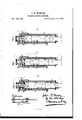
- Figures l, 2, and 3 are vertical sections of the engine, showing the operating parts in different positions.
- A is the cylinder and B the main piston, the latter being reduced in diameter at two places, so as to form with the cylinder the two annular chambers or passages m and n, as described hereafter, the piston being thus composed of three united sections, c, ct', and a", fitting snugly to the interior of the cylinder.
- On the .top of the main cylinder A is the cylindrical valve-chest D, containing the cylindrical valve E, which is composed of three sections, e, e', and e", fitting snugly in the chest, and which is reduced in diameter at two points, so as to form, with the said chest, two annular cham bers or passages, .c and y.
- a piston, Gr adapted to the interior of the main cylinder, the piston and valve being connected together by a rod, f, part of which is less in diameter than the opening in the top of the cylinder through which the said rod passes, for a purpose explained hereafter.
- the rod or plunger H at tached to or forming part of the main piston passes through a stufng box, h, at the bottom of the cylinder.
- a stufng box, h at the bottom of the cylinder.
- Fig. 1 the main piston has reached, or nearly reached, the limit of its upward movement, live steam from the annular chamber m having passed through the channel l to the space above the piston, and the pressure of this steam having forced the piston G and its valve E upward to the position shown, (6,) the steam above this piston G having escaped through the channel p into the annular charnber n, and thence through the outlet k.
- the piston now commences to descend, owing to the pressure of steam from the channel l, which is comparatively small, so that the commencement of the downward movement of the piston is slow, and free from sudden shocks.
- the main piston continues its upward movement until it uncovers the lower port of the channel l, when the live steam from the chamber m gains ac cess to the space above thc main piston; then the'under side of the valve-piston G is exposed to the full pressure of' live steam, is opposed b v the pressure ot' steam on the lesser area of the valve, and, as the main piston is supported below by a pressure ot' steam on an annular surface of greater area that of the valve, the instant rising ofthe said valve and its piston must take place, after which there is a repetition ot' the abovedescribed movements.
- a portion ot' the rodf which connects the valve with the piston G is somewhat less in diameter than the hole in the top of the cylinder through which the said rod passes.
- the rodf is arranged to iit snugl) ⁇ in the hole in the top ot' the cylinder, so that a small quantity ot' steam may be trapped between the piston and cover, to serve as a cushion for the former.
- the chamber u and outlet k" may be dispensed with, but I prefer to use them.
- valve-chest at the top ot' and in line with the cylinder a plan which facilitates construction, for reasons which will be familiar to those practically familiar with the construction ot' steamengines.
- the combination in a direct-action engine ot' a main piston, B, cylindrical valve E, and its piston G, adapted to the main cylinder ofthe engine, with inlets and outlets and ports and passages, arranged substantially as described, for the purpose specitied.
Description
f J. s. WARING.
DIRECT-ACTING ENGINE.
No.185,805. Patented Dec.26, 1876.
THE GRAPHIC CJJLY,
UNITE@ STATES PATENT OFFICE..
JOHN B. WARING, OF STAMFORD, CONN., ASSIGNOR OF ONE-HALF OF HIS Y RIGHT TO JOSEPH B. WILSON, OF PHILADELPHIA, PA.
IMPROVEMENT IN DIRECT-ACTING ENGINES.
Specification forming part of Letters Patent No. 185,805, dated December 26, 1876; application tiled November 23, 1876.
To all lwhom tt may concern Beit known that I, JOHN B. WARING, of Stamford, Connecticut, have invented a new and useful Improvement in Direct Acting Steam-Engines, of which the following is a specification The object of my invention is to construct a simple and economical direct-action 'steamengine, the valve of which shall be automatically operated by the steam alone, without the aid of external appliances usually employed for operating the valves of engines of this class.
In the accompanying drawing, Figures l, 2, and 3 are vertical sections of the engine, showing the operating parts in different positions.
A is the cylinder and B the main piston, the latter being reduced in diameter at two places, so as to form with the cylinder the two annular chambers or passages m and n, as described hereafter, the piston being thus composed of three united sections, c, ct', and a", fitting snugly to the interior of the cylinder. On the .top of the main cylinder A is the cylindrical valve-chest D, containing the cylindrical valve E, which is composed of three sections, e, e', and e", fitting snugly in the chest, and which is reduced in diameter at two points, so as to form, with the said chest, two annular cham bers or passages, .c and y. At the lower end of the valve is a piston, Gr, adapted to the interior of the main cylinder, the piston and valve being connected together by a rod, f, part of which is less in diameter than the opening in the top of the cylinder through which the said rod passes, for a purpose explained hereafter. The rod or plunger H at tached to or forming part of the main piston passes through a stufng box, h, at the bottom of the cylinder. There are a number of channels or passages, all of which will be referred to in the following description of the operation of the engine.
It may be stated in the outset that there are two inlets, o; and j, for live steam; that the annular chamber m of the main piston and the annular chamber y of the piston-valve are always exposed to the live steam; that there is a communication, t, (shown by dotted.lines,)
Fig. 3, between the annular chambery and the space above the piston-valve, on which there is consequently a constantlivesteam pressure, and that there are three outlets, k, 7c', and k, for the exhaust steam.
In Fig. 1 the main piston has reached, or nearly reached, the limit of its upward movement, live steam from the annular chamber m having passed through the channel l to the space above the piston, and the pressure of this steam having forced the piston G and its valve E upward to the position shown, (6,) the steam above this piston G having escaped through the channel p into the annular charnber n, and thence through the outlet k. The piston now commences to descend, owing to the pressure of steam from the channel l, which is comparatively small, so that the commencement of the downward movement of the piston is slow, and free from sudden shocks. It should here be understood that while the piston descends the steam below it is being exhausted through the passage w, through the small cylinder D, below its pistonvalve, and thence through the exhaust-passage k'. As the main piston descends it closes the passage l, but before the latter is quite closed the piston exposes the port c communicating with the inletj through a channel, M, and through the annular chamber y, so that the piston continues its descent under a full head of live steam.
When the piston B has reached the position, Fig. 3, the exhaust-port lc has been closed and the channelp has formed a communication between the annular steam chamber m and the space above the valvepiston G, and the consequence of this has been the sudden descent of the said piston and valve. By this movement the annular chamber y of the valve is made to communicate with the inletj and also with the channel w through which the live steam passes to the space beneath the main piston. At the same time there is an open communication through the port '0, passage M, and annular chamber .r of the valve between the exhaust-outlet k and the space above the piston B. The consequence of this will be the rising or return movement of the piston.
Turning back to the arrival of the piston in its descent to the position, Fig. 3, and to the downward movement ot' the valve and its piston, it will be understood that the latter in its descent is acting against steam above the main piston. This, however, is not suflcent to prevent the downward movement of the valve, i'or there is the pressure of live steam above the piston G, plus the pressure of live steam on the top of the valve, and the coinbined areas ot the two are greater than the area ot'the main piston. The main piston continues its upward movement until it uncovers the lower port of the channel l, when the live steam from the chamber m gains ac cess to the space above thc main piston; then the'under side of the valve-piston G is exposed to the full pressure of' live steam, is opposed b v the pressure ot' steam on the lesser area of the valve, and, as the main piston is supported below by a pressure ot' steam on an annular surface of greater area that of the valve, the instant rising ofthe said valve and its piston must take place, after which there is a repetition ot' the abovedescribed movements.
As before remarked, a portion ot' the rodf which connects the valve with the piston G is somewhat less in diameter than the hole in the top of the cylinder through which the said rod passes. In other words, there is an annular spaee around a portion of the rod, through which space the steam above the piston G can escape to the outlet k', during the rapid upward movement of' the said piston. rlhe lower portion ot' the rodf, however, is arranged to iit snugl)` in the hole in the top ot' the cylinder, so that a small quantity ot' steam may be trapped between the piston and cover, to serve as a cushion for the former.
' or other machines ot' like character.
lt will he seen without further description that a reciprocating motion is imparted to the main piston without the usual valve-operating appliances connnon to other direct-action engines, and that the engine may be used in connection with a pump, or may form part of a steam-hammer or of a rock-drilling machine, It will also be evident to those familiar with engines of this class that the passages and ports may he arranged in different Ways without departing from the main features of the invention.
The chamber u and outlet k" may be dispensed with, but I prefer to use them.
An important feature of my invention is the arrangement ofthe valve-chest at the top ot' and in line with the cylinder, a plan which facilitates construction, for reasons which will be familiar to those practically familiar with the construction ot' steamengines.
I claim as my invention- 1. The combination, in a direct-action engine ot' a main piston, B, cylindrical valve E, and its piston G, adapted to the main cylinder ofthe engine, with inlets and outlets and ports and passages, arranged substantially as described, for the purpose specitied.
2. An opening in the top ot' the main c vliuder, communicating with an exhaust-outlet, in combination with the rodf of the valve and its piston, the upper portion ot' said rod being less than the opening, and the lower portion being made to tit the same, all as set forth.
In testimony whereofl I have signed my name to this specification, in the presence of two subscribing witnesses.
JOHN B. WARING.
Witnesses HERMANN MoEssNEs, HARRY SMITH.
Publications (1)
| Publication Number | Publication Date |
|---|---|
| US185805A true US185805A (en) | 1876-12-26 |
Family
ID=2255212
Family Applications (1)
| Application Number | Title | Priority Date | Filing Date |
|---|---|---|---|
| US185805D Expired - Lifetime US185805A (en) | Improvement in direct-acting engines |
Country Status (1)
| Country | Link |
|---|---|
| US (1) | US185805A (en) |
-
0
- US US185805D patent/US185805A/en not_active Expired - Lifetime
Similar Documents
| Publication | Publication Date | Title |
|---|---|---|
| US185805A (en) | Improvement in direct-acting engines | |
| US449457A (en) | Starting valve for compound engines | |
| US242995A (en) | shortt | |
| US345056A (en) | Valve | |
| US664901A (en) | Valve-gear. | |
| US999642A (en) | Steam-pump. | |
| US748758A (en) | Pumping-engine | |
| US294999A (en) | halsey | |
| US208797A (en) | Improvement in direct-acting steam-pumps | |
| US498635A (en) | Steam-engine valve | |
| US420801A (en) | hultaren | |
| US292697A (en) | shoett | |
| US460617A (en) | Direct-acting engine | |
| US750486A (en) | Steam-actuated valve | |
| US431413A (en) | Valve for steam-pumps | |
| US377938A (en) | Steam pump | |
| US416823A (en) | Steam-engine | |
| US514962A (en) | Steam-actuated valve | |
| US558199A (en) | Valve for steam-pumps | |
| US509847A (en) | Cofran i | |
| US369659A (en) | Steam-actuated valve | |
| US592038A (en) | aborn | |
| US644585A (en) | Steam-pump. | |
| US134212A (en) | Improvement in steam pumping-engines | |
| US847897A (en) | Steam-actuated valve for pumping-engines. |