US1858038A - Lug strap - Google Patents
Lug strap Download PDFInfo
- Publication number
- US1858038A US1858038A US456894A US45689430A US1858038A US 1858038 A US1858038 A US 1858038A US 456894 A US456894 A US 456894A US 45689430 A US45689430 A US 45689430A US 1858038 A US1858038 A US 1858038A
- Authority
- US
- United States
- Prior art keywords
- layers
- strap
- lug
- lug strap
- strips
- Prior art date
- Legal status (The legal status is an assumption and is not a legal conclusion. Google has not performed a legal analysis and makes no representation as to the accuracy of the status listed.)
- Expired - Lifetime
Links
- 238000000034 method Methods 0.000 description 8
- 230000015572 biosynthetic process Effects 0.000 description 5
- 230000006835 compression Effects 0.000 description 3
- 238000007906 compression Methods 0.000 description 3
- 230000003014 reinforcing effect Effects 0.000 description 3
- 239000000853 adhesive Substances 0.000 description 2
- 230000001070 adhesive effect Effects 0.000 description 2
- 238000010276 construction Methods 0.000 description 2
- 239000000463 material Substances 0.000 description 2
- 208000027418 Wounds and injury Diseases 0.000 description 1
- 238000005452 bending Methods 0.000 description 1
- 230000006378 damage Effects 0.000 description 1
- 238000007688 edging Methods 0.000 description 1
- 208000014674 injury Diseases 0.000 description 1
- 238000004519 manufacturing process Methods 0.000 description 1
- 239000002184 metal Substances 0.000 description 1
- 239000004753 textile Substances 0.000 description 1
Images
Classifications
-
- D—TEXTILES; PAPER
- D03—WEAVING
- D03D—WOVEN FABRICS; METHODS OF WEAVING; LOOMS
- D03D49/00—Details or constructional features not specially adapted for looms of a particular type
- D03D49/24—Mechanisms for inserting shuttle in shed
- D03D49/26—Picking mechanisms, e.g. for propelling gripper shuttles or dummy shuttles
- D03D49/38—Picking sticks; Arresting means therefor
Definitions
- My present invention is a novel and improved lug strap and includes also the novel process of making the same.
- My present invention obviates these difll- 2 culties and permits a lug strap to be formed on a plurality of layers in a novel method and then to be stamped or formed into U- shaped or final construction, insuring a smooth and relatively unrufiled or wrinkled,
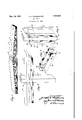
- Fig. 1 is a View, artly in perspective, showing the method of laying up the strips
- Fig. 2 is a view also in perspective illustrating a device for forming the same into U-shaped or final contour
- Fig. 3 is a view illustrating the forming action with the edges of the lug strap working or extending during the U-shaped conforming operation
- Fig. 4 shows the completed lug strap with the roughened edges removed.
- I prepare a number of layers of strips of suitable width and length to total the length of the lug strap desired, and a .0
- a n improved process of making lug straps whlch consists in assembling a plurality of strips of textile. material, certain of said strips being of less length than the total length of the strap and greater than one-half of said length, constructed and arranged to provide predetermined portions to constitute a reinforcing overlap at the central portion, and formlng said plurality of-straps into final or U-shaped form.
Landscapes
- Engineering & Computer Science (AREA)
- Textile Engineering (AREA)
- Buckles (AREA)
Description
May 10, 1932. J. H. CHADBOURNE LUG STRAP Filed May 29 1930 Patented May 10, 1932 UNITED STATES PATENT OFFICE JOSEPH H. CHADBOURNE, F DANIELSON, CONNECTICUT, ASSIGNOR T0 EJH. JACOBS MFG. 00., A. CORPORATION OF CONNECTICUT LUG swan Application filed May 29, 1930. Serial No. 456,894.
My present invention is a novel and improved lug strap and includes also the novel process of making the same.
In the manufacture of lug straps for use in actuating the picker of looms it has heretofore been customary to make the same in a plurality of layers of unrolled canvas strlps or sheets, together with reinforcinglayers or portions, and all bein solidified by adhesive.
m As such prior metho s and the resulting lug straps were made in a substantially straight or horizontal plane or mass, and then either afterward bent into U-shape or proper'form, the resulting structure was more or less wrinkled or corrugated around the inner surface of the U-shaped portion. This is necessarily due to folding in a plurality of layers which are laid fiat and secured together, the inner portion of the curve being on a shorter g radius than the outer layers and hence under compression during the U-shaped formation, while the outermost layers are under stretching tension.
My present invention obviates these difll- 2 culties and permits a lug strap to be formed on a plurality of layers in a novel method and then to be stamped or formed into U- shaped or final construction, insuring a smooth and relatively unrufiled or wrinkled,
3 corrugated surface on the inner part of the U Where the contacting surface of the lug strap against the picker stick bears.
In carrying out my present invention I accomplish the foregoing desirable results by 3 laying up a plurality of layers, preferably in the form of strips, elimating and saving the interrolling action. and preferably having these layers of slightly greater length than one of the legs of the resulting lug strap 40 overlapping the same in alternative positions at the center portion, while assembling the strips or layers.
Then either before or after the same are treated with the desirable adhesive, and beforeit can set, I apply the thus formed lug strap to a mould forming or stamping the same into the desired and final U-shaped form, simultaneously permitting the plurality of layers to slide on each other from the center portion outwardly to the free ends of each leg as the material is relatively displaced during the U-shaped formation. Thereafter I trim off the rough outer edging of each leg and retain the same in a mould or moulds until set and solidified. By thus permitting, in any manner whatever, the layers or strips to slide by each other during the U-shaped formation, I produce a smooth surfaced structure, retaining the entire strength of the plurality of layers in laminated form and 6opreventing distortion either from compression or stretching, as was a prior difficulty in all old known methods.
I believe that my present novel method of forming a lug strap, permitting the layers to 66 slide or work during bending, and thus forming the lug strap with the full tensile strength of each layer at the U-shaped portion and with the inner surface smooth and unwririkled, is a distinct novelty, both in the 70 method and in the resulting article and I wish to claim the same herein broadly.
Referring to the drawings, illustrating a preferred embodiment of the present invention,
Fig. 1 is a View, artly in perspective, showing the method of laying up the strips;
Fig. 2 is a view also in perspective illustrating a device for forming the same into U-shaped or final contour;
Fig. 3 is a view illustrating the forming action with the edges of the lug strap working or extending during the U-shaped conforming operation, and
Fig. 4 shows the completed lug strap with the roughened edges removed.
As illustrated in the drawing in its preferred form, I prepare a number of layers of strips of suitable width and length to total the length of the lug strap desired, and a .0
- formed, thus plurality of other strips of less length interlaid between the same of slightly more than v one-half the len h of the strap desired overis fitted to a conforming device. This may] be any suitable means to sha e up the lug strap thus formed into its al U-shaped construction, thus for example, I may divide a pair of clamping members 6 and 7 adapted to fit and hold the central portion of the lug strap, the member 7 being preferably of the desired thickness equal to the width of the U-shaped' formation of the lug strap and about which the resulting legs 10 and 12 are formed.
To complete this conformation of the strap 5, I provide a pair of hinged leaves or clamps 8 and 9, hinged or otherwise pivotally secured to the clamping member 6 at 13. During this clamping action the lug strap is formed into the desired contour with the extending portions 10 or 12, as shown, and the layers or sections slide or work slightly upon each other during this conforming action-as in folding a deck of cards, with the result that the projecting edges, illustrated at 15 and 16 in Fig. 3 and in dotted lines in Fig. 4, are permitting the layers to lay smoothly particularly around the heat or base 20 It will thus be seen that m novel method produces a strong laminated ug strap structure with the inner end 21 of the U smooth in surface, and hence giving more wear and longer life. I believe that the building of the lug strap with layer strips in this way, overlapping at the center to give reinforcing, either with or without metal reinforcing elements in the central portion, is a distinct novelty and I wish to claim this feature. Also the formation of any layers, whether in strips or interrolled, whereby the layers are permitted to move, slide, or work past each other, as shown in Figs. 3 and 4, thus giving a smooth and uniform contour around the base .20 and particularly on the inner surface 21,
preventing corrugating or wrinkling, and preventing injury to the layers of the lug strap either by compression on the inner layers and stretching on the outer layers, is distinctly new and I claim this feature broadly.
I believe also that the resulting lu strap with the smooth inner surface 21 is a 'stinct novelty and I claim same broadly.
Having thus described my invention, what I claim as new is:
A n improved process of making lug straps whlch consists in assembling a plurality of strips of textile. material, certain of said strips being of less length than the total length of the strap and greater than one-half of said length, constructed and arranged to provide predetermined portions to constitute a reinforcing overlap at the central portion, and formlng said plurality of-straps into final or U-shaped form.
In testimony whereof, I have signed my name to this specification.
JOSEPH H. CHADBOURNE.
Priority Applications (1)
| Application Number | Priority Date | Filing Date | Title |
|---|---|---|---|
| US456894A US1858038A (en) | 1930-05-29 | 1930-05-29 | Lug strap |
Applications Claiming Priority (1)
| Application Number | Priority Date | Filing Date | Title |
|---|---|---|---|
| US456894A US1858038A (en) | 1930-05-29 | 1930-05-29 | Lug strap |
Publications (1)
| Publication Number | Publication Date |
|---|---|
| US1858038A true US1858038A (en) | 1932-05-10 |
Family
ID=23814572
Family Applications (1)
| Application Number | Title | Priority Date | Filing Date |
|---|---|---|---|
| US456894A Expired - Lifetime US1858038A (en) | 1930-05-29 | 1930-05-29 | Lug strap |
Country Status (1)
| Country | Link |
|---|---|
| US (1) | US1858038A (en) |
-
1930
- 1930-05-29 US US456894A patent/US1858038A/en not_active Expired - Lifetime
Similar Documents
| Publication | Publication Date | Title |
|---|---|---|
| US2426058A (en) | Plastic sheet material and method | |
| US1902032A (en) | Method of and apparatus for making flexible veneer | |
| US1906392A (en) | Process of bending wood | |
| US1858038A (en) | Lug strap | |
| US1816594A (en) | Method of and apparatus for making sheets and irregular surface contours | |
| US1808003A (en) | Gypsum wall board | |
| US1847310A (en) | Process of manufacturing pipes | |
| US1969918A (en) | Roof decking | |
| US1834554A (en) | Method of making channel strips | |
| US1849054A (en) | Apparatus for the manufacture of metal tubes | |
| US3124851A (en) | Figure | |
| US2088889A (en) | Stitching device for tire building machines | |
| US2669280A (en) | Method of makign v-belts | |
| US1905398A (en) | Method and apparatus for making a sill plate | |
| US1885280A (en) | Reenforced paper and method of making the same | |
| US1909993A (en) | Lug strap and method of making the same | |
| US1789137A (en) | Reenforced wooden bow and method of manufacture thereof | |
| US1620239A (en) | Art of paper-ware manufacture | |
| US1737243A (en) | Edge binder | |
| US2854056A (en) | Method of treating metal strip for the formation of venetian blind slats and the like | |
| US1594612A (en) | Insulating tape | |
| US2074986A (en) | Method of making welded sheet metal golf shafts and welding shim therefor | |
| US1695317A (en) | Cork facing for rolls | |
| US1664259A (en) | Method of building tire casings | |
| US1616063A (en) | Adjustable cylindrical tubing and method of making the same |