US1857798A - Mixing and drying machine - Google Patents
Mixing and drying machine Download PDFInfo
- Publication number
- US1857798A US1857798A US426453A US42645330A US1857798A US 1857798 A US1857798 A US 1857798A US 426453 A US426453 A US 426453A US 42645330 A US42645330 A US 42645330A US 1857798 A US1857798 A US 1857798A
- Authority
- US
- United States
- Prior art keywords
- drum
- charge
- bucket
- buckets
- mixing
- Prior art date
- Legal status (The legal status is an assumption and is not a legal conclusion. Google has not performed a legal analysis and makes no representation as to the accuracy of the status listed.)
- Expired - Lifetime
Links
Images

Classifications
-
- E—FIXED CONSTRUCTIONS
- E01—CONSTRUCTION OF ROADS, RAILWAYS, OR BRIDGES
- E01C—CONSTRUCTION OF, OR SURFACES FOR, ROADS, SPORTS GROUNDS, OR THE LIKE; MACHINES OR AUXILIARY TOOLS FOR CONSTRUCTION OR REPAIR
- E01C19/00—Machines, tools or auxiliary devices for preparing or distributing paving materials, for working the placed materials, or for forming, consolidating, or finishing the paving
- E01C19/02—Machines, tools or auxiliary devices for preparing or distributing paving materials, for working the placed materials, or for forming, consolidating, or finishing the paving for preparing the materials
- E01C19/05—Crushing, pulverising or disintegrating apparatus; Aggregate screening, cleaning, drying or heating apparatus; Dust-collecting arrangements specially adapted therefor
Definitions
- the present invention may be said to'have for its object to.
- I employja Y ⁇ 2o horizontal, rotatable drum having in the peripheral wall a combined inlet andv outlet opening or openings, the interior of the drum being provided with one or more bucketsso formed and ⁇ so disposed that, when the drum 25 is turned to bring the opening or oneo the openings toward'thetop, a charge' may be delivered through-such opening and be retained in the drum; the rotation of the drum in one direction, thereafter, causing the 8l) charge to be alternately ,liftedlandspilled across the interior of the drum;- and the rotation of the drum inthe kopposite'direction permitting the charge to flow outofthe drum V through the opening or any one of them, if there be more than one, when it is brought tothe underside of 'the drum.
- the present invention may be said to have for its object toproduce ai'simple and-"noveldoor- 40 less mixing drum into whiclra charge'may simply be poured, in which ⁇ it will be thoroughly"1nixedand from which ythe charge will run by gravity, through the merev angular positioning? ofV the ydrum and the rotation thereof first in one direction andthen ⁇ v the other.'
- Fig; 3 ;Y Figs. 3 and 4 are sections through drum,'atfright angles to the lengaxis'there ⁇ of, on the same scale' as Fig. 2, the ,drum be#v ing two' diEerent 1 angularfp'sitionsfj and Fig. .5: is I a ViewY ⁇ vsimilar to 'S'an'd" "4i showing only; a fragment at'thebottombf ing ,properly locat ⁇ ed",with respect'tofthe bucket.”
- Eachbucket may, conveniently be in the form toff'applate, 2 extending in;
- The.loukets'v are' symme'trically disposedl ⁇ y'vit-h 'respect 4tot a plane extending between them and containing the axis of rotation of the drum, the partition-like portions of the plates making an acute angle with such plane.
- the plane in question may be regarded as being represented by line 2-2 on Fig. 3.
- In the peripheral wall of the drum preferably adjacent to each bucket and on the side of the latter opposite that on which the trough is situated.
- heat may be applied in any suitable way.
- the material As the material is spilled from the buckets it spreadsout in a thin layer or stream so as to leave the surface of each particle or piece exposed and thus permit fthe" vapors to escape freely.l
- the windows or openings inthe periphery of the drum constitute large vents or chimneys through which the vapors can freely leave the drum. It will be seen., that excepting only during a small part ofthe angular movement of the drum there willbe one of thewindows or openings in the upper .half of the drum, so that the vapors need only rise in order to find an exit.
- the drum is supported from one head 5 which is 'fixed upon the end of a suitable, horizontal, rotatable shaft 6.
- the other head 7 of the drum has a large central opening 8 bounded by an annularfiange 9 extending a short distance into the drum.
- This opening is substantially closed by means of a stationary disc or plate 10 held close to the drum outside of the head.l
- This plate V carries an open-ended sleeve or shell 11 of considerable diameter extending through the plate and into the drum, preferably eccentrically of the drum soas to be positioned in the lower half-of the latter.
- a baflie plate 12 Fixed to the plate 10 andto the sleeve or shell 11, and lying above the sleeve or shell, is a baflie plate 12 extending from one end of the drum to the other and downwardly inclined in such a directionthat when the materialis spilled from the buckets during the mixing and drying operation, the material falls on thisbaflie plate .and slides ldown over the latter before dropping into the bottom 'of the drum.
- a suitable burner or burners 13, projecting into the outer end of the sleeve or shellll and adapted to throwsa'flame into the interior ofthe drum, may be employed as the heating means.
- the ballie plate may be made sufficiently wide so that the buckets lwilljust clear the same during the rotation of the drum.
- baffle plate Furthermore there may be at the long edges of the baffle plate downwardlyextending flanges 14 and 15k that will act as deflectors for the flame and combustion gases and prevent them from shooting upv directly past the edges of the baffle plate.
- flanges 14 and 15k that will act as deflectors for the flame and combustion gases and prevent them from shooting upv directly past the edges of the baffle plate.
- e v Y The head 5.of the drum may be provided with a central internal flame deflector 16 that will prevent the fla-me from striking'directly againstthe headas it leaves the burners.
- drum is adapted to be driven from 'a suitable driving shaft 17, through gearing 18 forming part of a suitable reversing mechanism 19; the drum being caused to turn in one direct-ion or the other, or to be brought to rest by means of a control handle 20.
- Such drives are old and well known and I therefore have intended to give only a conventional illustration thereof.
- I claim z- 1 In a machine of the character described, a horizontal rotatable drum, buckets fixed in the drum and comprising members extending inwardly vfrom the peripheral wall of the drum and each having at its inner end on the side that is in advance when the drum is turned in one direction, a trough extending lengthwise of the drum, and there being combined inlet and outlet openings in the said wall on the sides of said members opposite those on which the troughs are located, the said wall being continuous except where said openings occur.
- a horizontal rotatable drum having a continuous peripheral wall
- a bucket fixed in the drum and comprising a member extending inwardly from the peripheral wall of the drum and having at its inner end on the side that is in advance when the drum is turned in one direction, a trough extending lengthwise of the drum, and there being a combined inlet and outlet opening in the said wall on the y side of said member opposite that on which the trough is located.
- a horizontal rotatable drum having a continuous peripheral wall, bucket members fixedV within the drum in spaced relation to each other and constructed and arranged to cause a charge in the drum to be alternatelyT raised and spilled back into the drum when the drum is rotated in one direction, there being combined inlet and outlet openings in the .periphery of the drum, each opening being adjacent to one of the buckets on the side that is the trailing side when the drum is rotated in the aforesaid direction.
- a horizontal rotatable drum having a continuous peripheral wall, bucket members fixed within the drum in spaced relation to each other and constructed'and arranged to canse a charge in the drum to be alternately raised and spilled back into the drum when the drum is rotated in one direction, there being combined inlet and outletopenings in the periphery of the drum, each opening being adjacent to one of the buckets on the side that is the trailing side when the drum is rotate-d in the aforesaid direction, and means for heating the drum internally.
- a horizontal rotatable drum having a continuous peripheral wall, two diametrically opposed buckets extending inwardly from the peripheral wall of the drum ⁇ adapted to lift loose material in the drum above the axis of the latter and then spill it when the drum is rotated in one direction and act simply as more or less radial partitions when the drum is rotated in the other direction, and there being combined inlet and outlet. openings in said wall adjacent to said buckets and on the sides thereof that are the trailing ⁇ sides when the drum is rotated in the first mentioned direction.
- a horizontal rotatable drum having a con tinuous peripheral wall, two diametrically opposed buckets extending inwardly from the peripheral wall of the drum adapted to lift loose material in the drum above the axis of the latter and then spill it when the drum is rotated in one direction and act simply as more or less radial partitions when the drum is rotated in the other direction, and there being combined inlet and outlet openings in said wall adjacent to said buckets and on the sides thereof that are the trailing sides when the drum is rotated in the first mentioned direction, and means to heat the drum internally.
Landscapes
- Engineering & Computer Science (AREA)
- Architecture (AREA)
- Civil Engineering (AREA)
- Structural Engineering (AREA)
- Drying Of Solid Materials (AREA)
Description
May 10, 1932- A. B. WEBB MIXING AND DRYING MACHINE Filed Feb. 7, 1930 2 Sheets-Sheet l May 1-0, 1932. A.B. WEBB 1,857,798
V MIXING AND DRYING MACHINE Filed Feb. 7. 1930 2 Sheets-Sheet 2 Patented May 10,- 1932 UNITED STATES PATENT f ARTHUR B. WEBB, on MILWAUKEEWISCONSIN, AssIGNonmo THE nien'rwax con- PORATION, :A CORPORATION OF INDIANA1 MIXING 4Ann DRYING MACHINE appuanon mea February 7, 1930. serial N. 426,453. Y
"In preparing a mixture for bituminous concrete, the various solid aggregates must be thoroughly mixed and dried. The drying cannot be rapidly and economically eiected unless the watery vapors can be readily-freed from the mass and be quickly withdrawn or allowed to escape.
Viewed in a speclfic aspect, the present invention may be said to'have for its object to.
In carrying out my invention I employja Y`2o horizontal, rotatable drum having in the peripheral wall a combined inlet andv outlet opening or openings, the interior of the drum being provided with one or more bucketsso formed and` so disposed that, when the drum 25 is turned to bring the opening or oneo the openings toward'thetop, a charge' may be delivered through-such opening and be retained in the drum; the rotation of the drum in one direction, thereafter, causing the 8l) charge to be alternately ,liftedlandspilled across the interior of the drum;- and the rotation of the drum inthe kopposite'direction permitting the charge to flow outofthe drum V through the opening or any one of them, if there be more than one, when it is brought tothe underside of 'the drum. j Therefore, viewed in one of its aspects, the present invention may be said to have for its object toproduce ai'simple and-"noveldoor- 40 less mixing drum into whiclra charge'may simply be poured, in which` it will be thoroughly"1nixedand from which ythe charge will run by gravity, through the merev angular positioning? ofV the ydrum and the rotation thereof first in one direction andthen`v the other.'
VVhe're-there is 'a heating yand a drying of the charge, the uncovered openingl orl openi ings in the periphery of the drum permits #i0 the free' escape ofthe vapors and consequent#I ly A'an effective ventilation f of "the drum; Therefore, viewed Vin, one of its ',aspects,"thje presentv invention may bez saidfto (have for `-its' object to `producey a simple and novel drying drumv so constructed that during l'the greater part of 'the time, atleast, when the drum is rotating, there willbe' a" large lopen venti' or vents in the drum ;"fwhereby the vapors may the charge will be retained until"`it isV desired to dump'the same] 'ii The Avarious features of novelty whereby my invention is characterized will hereinafter be; pointed out,y with "parti'cula'rity' in "the f.,
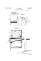
claims; but,for a full understanding of my invention and oft its, 0bjects and,V advantages; reference may be had to the following de-A tailed description taken? in connectionwiththe accompanying drawings, wherein Y Figurelis an elevation of' a machine enrbodying the present invention in 4'ne f of Aits forms; Fig. 2 isa vertical section, on allarger scale, taken approximatelyj on", line. of
Fig; 3 ;Y Figs. 3 and 4 are sections through drum,'atfright angles to the lengaxis'there` of, on the same scale' as Fig. 2, the ,drum be#v ing two' diEerent 1 angularfp'sitionsfj and Fig. .5: is I a ViewY` vsimilar to 'S'an'd" "4i showing only; a fragment at'thebottombf ing ,properly locat`ed",with respect'tofthe bucket." In the arrangement illustrated :and to whichthedetailed description will b e conned, there areI two buckets and two openings or windows. Eachbucket "may, conveniently be in the form toff'applate, 2 extending in;
wardlylfrom'theperipheral wall ofthe drum and; from one end of the drum tothe other; the free' marginal Vportion of 'each' plate being bent laterally into the shape:V offa'ftrough 13 lying 0n one' side ofthe' plate."i The.loukets'v are' symme'trically disposedl` y'vit-h 'respect 4tot a plane extending between them and containing the axis of rotation of the drum, the partition-like portions of the plates making an acute angle with such plane. The plane in question may be regarded as being represented by line 2-2 on Fig. 3. In the peripheral wall of the drum, preferably adjacent to each bucket and on the side of the latter opposite that on which the trough is situated.
is a comparatively wide window or opening extending approximately throughout the bucket will be carried around underneath the charge which will fill the bucket and be lifted by the latter as indicated in Figa. n
`It will be'seen that as the drum continues to revolve so as to carry the filled bucket upwardly from the position indicated in Fig. 4, the charge will begin to spill over the edge of the trough and will drop down into the bottom of the drum. Howevergrbefore the material' begins to spill` from the bucket, the latter has reached a position in which it forms aroof Yor canopy overthe adjacent opening or window, so that the overowing material will not escape through the window. By the time the drum has -been turned throughv an angle of 180,1so that the buckets have changed positions with each other and the lower bucket in Fig. 3 has become the upper bucket, the greater part of thechargewill havebeen spilled out of the previously filled bucket andrbeen deposited in the bottom of the drum. Furtherirotation of lthe drum, in
the same direction, will cause the small einan-V tity of material inthe trough of the. upper bucketto be emptied and the ventire charge Y now in the bottom .ofthe drum to be picked up by the second bucket. As the drum makes one revolution after another', the charge is picked up kand spilled back into the drum first by one bucket and then by the other.
When it is desired to dump the charge. the drum is simply turned in the clockwise direction as` viewed in Figs. 3 and 4. namely. in the direction of the arrow .in Fig. .5. The buckets now do not act as lifters. for the Charge, but drop away `from theV same and permit it to gravitate into the bottom of' the drum. When one of the windows or openings reaches the bottom, as it is about todo in Fig. 5,-the charge flows out through the same. 1 In V short,to fill the drum, it VisturnedA to bring one ofthe openings at the top and, in order to empty the drum, it is turned in the clockwise direction to bring one of the windows to the bottom.
When the material that is handled by the drum is to be dried, heat may be applied in any suitable way. As the material is spilled from the buckets it spreadsout in a thin layer or stream so as to leave the surface of each particle or piece exposed and thus permit fthe" vapors to escape freely.l The windows or openings inthe periphery of the drum constitute large vents or chimneys through which the vapors can freely leave the drum. It will be seen., that excepting only during a small part ofthe angular movement of the drum there willbe one of thewindows or openings in the upper .half of the drum, so that the vapors need only rise in order to find an exit.
In the particularform of'my invention illustrated I have provided means for heating the drum from' the inside. To this end, the drum is supported from one head 5 which is 'fixed upon the end of a suitable, horizontal, rotatable shaft 6. The other head 7 of the drum has a large central opening 8 bounded by an annularfiange 9 extending a short distance into the drum. This opening is substantially closed by means of a stationary disc or plate 10 held close to the drum outside of the head.l This plate Vcarries an open-ended sleeve or shell 11 of considerable diameter extending through the plate and into the drum, preferably eccentrically of the drum soas to be positioned in the lower half-of the latter. Fixed to the plate 10 andto the sleeve or shell 11, and lying above the sleeve or shell, is a baflie plate 12 extending from one end of the drum to the other and downwardly inclined in such a directionthat when the materialis spilled from the buckets during the mixing and drying operation, the material falls on thisbaflie plate .and slides ldown over the latter before dropping into the bottom 'of the drum. .A suitable burner or burners 13, projecting into the outer end of the sleeve or shellll and adapted to throwsa'flame into the interior ofthe drum, may be employed as the heating means. The ballie plate may be made sufficiently wide so that the buckets lwilljust clear the same during the rotation of the drum. Furthermore there may be at the long edges of the baffle plate downwardlyextending flanges 14 and 15k that will act as deflectors for the flame and combustion gases and prevent them from shooting upv directly past the edges of the baffle plate. e v Y The head 5.of the drum may be provided with a central internal flame deflector 16 that will prevent the fla-me from striking'directly againstthe headas it leaves the burners.
My improved machine, whether it be used simply as a mixingmachine or as a mixing and dryingmachine, maybe. driven. in any suitable wayf-dependingupon vthe nature of the work. Y In the arrangement shown, the
drum is adapted to be driven from 'a suitable driving shaft 17, through gearing 18 forming part of a suitable reversing mechanism 19; the drum being caused to turn in one direct-ion or the other, or to be brought to rest by means of a control handle 20. Such drives are old and well known and I therefore have intended to give only a conventional illustration thereof.
While I have illustrated and described with particularity only a single preferred form of my invention, I do not desire to be limited to the exact structural details thus illustrated and described; but intend to cover all forms and arrangements which come within the definitions of Vmy invention constituting the appended claims.
I claim z- 1. In a machine of the character described, a horizontal rotatable drum, buckets fixed in the drum and comprising members extending inwardly vfrom the peripheral wall of the drum and each having at its inner end on the side that is in advance when the drum is turned in one direction, a trough extending lengthwise of the drum, and there being combined inlet and outlet openings in the said wall on the sides of said members opposite those on which the troughs are located, the said wall being continuous except where said openings occur.
2. In a machine of the character described. a horizontal rotatable drum having a continuous peripheral wall, a bucket fixed in the drum and comprising a member extending inwardly from the peripheral wall of the drum and having at its inner end on the side that is in advance when the drum is turned in one direction, a trough extending lengthwise of the drum, and there being a combined inlet and outlet opening in the said wall on the y side of said member opposite that on which the trough is located.
3. In a machine of the character described, a horizontal rotatable drum having a continuous peripheral wall, bucket members fixedV within the drum in spaced relation to each other and constructed and arranged to cause a charge in the drum to be alternatelyT raised and spilled back into the drum when the drum is rotated in one direction, there being combined inlet and outlet openings in the .periphery of the drum, each opening being adjacent to one of the buckets on the side that is the trailing side when the drum is rotated in the aforesaid direction.
4. In a machine of the character described, a horizontal rotatable drum having a continuous peripheral wall, bucket members fixed within the drum in spaced relation to each other and constructed'and arranged to canse a charge in the drum to be alternately raised and spilled back into the drum when the drum is rotated in one direction, there being combined inlet and outletopenings in the periphery of the drum, each opening being adjacent to one of the buckets on the side that is the trailing side when the drum is rotate-d in the aforesaid direction, and means for heating the drum internally.
5. In a machine of the character described, a horizontal rotatable drum having a continuous peripheral wall, two diametrically opposed buckets extending inwardly from the peripheral wall of the drum` adapted to lift loose material in the drum above the axis of the latter and then spill it when the drum is rotated in one direction and act simply as more or less radial partitions when the drum is rotated in the other direction, and there being combined inlet and outlet. openings in said wall adjacent to said buckets and on the sides thereof that are the trailing` sides when the drum is rotated in the first mentioned direction.
6. In a machine of the character described,
a horizontal rotatable drum having a con tinuous peripheral wall, two diametrically opposed buckets extending inwardly from the peripheral wall of the drum adapted to lift loose material in the drum above the axis of the latter and then spill it when the drum is rotated in one direction and act simply as more or less radial partitions when the drum is rotated in the other direction, and there being combined inlet and outlet openings in said wall adjacent to said buckets and on the sides thereof that are the trailing sides when the drum is rotated in the first mentioned direction, and means to heat the drum internally.
In testimony whereof, I sign this specifica-
Priority Applications (1)
| Application Number | Priority Date | Filing Date | Title |
|---|---|---|---|
| US426453A US1857798A (en) | 1930-02-07 | 1930-02-07 | Mixing and drying machine |
Applications Claiming Priority (1)
| Application Number | Priority Date | Filing Date | Title |
|---|---|---|---|
| US426453A US1857798A (en) | 1930-02-07 | 1930-02-07 | Mixing and drying machine |
Publications (1)
| Publication Number | Publication Date |
|---|---|
| US1857798A true US1857798A (en) | 1932-05-10 |
Family
ID=23690861
Family Applications (1)
| Application Number | Title | Priority Date | Filing Date |
|---|---|---|---|
| US426453A Expired - Lifetime US1857798A (en) | 1930-02-07 | 1930-02-07 | Mixing and drying machine |
Country Status (1)
| Country | Link |
|---|---|
| US (1) | US1857798A (en) |
-
1930
- 1930-02-07 US US426453A patent/US1857798A/en not_active Expired - Lifetime
Similar Documents
| Publication | Publication Date | Title |
|---|---|---|
| US2421345A (en) | Mixer | |
| US2338820A (en) | Concrete mixer | |
| US4197014A (en) | Asphalt regenerating apparatus | |
| US4955722A (en) | Appliance for the preparation of bituminous coated products with a stationary mixer | |
| US3752445A (en) | Screw lifter mixer | |
| US1774649A (en) | Method of making paving material | |
| US1857798A (en) | Mixing and drying machine | |
| US1771321A (en) | Emulsifier, mixer, and the like | |
| US1405707A (en) | Concrete mixer | |
| CN109423944A (en) | A kind of modified pitch production line | |
| US2080508A (en) | Mixing and screening apparatus for fertilizer materials and the like | |
| US1171583A (en) | Ore-roasting apparatus. | |
| CN206982978U (en) | Construction agitating device | |
| US1973812A (en) | Seed treating machine | |
| US1915750A (en) | Apparatus for feeding powdered fuels | |
| US932789A (en) | Apparatus for hydrating lime. | |
| US2772083A (en) | Drier and mixer for fluent solid material | |
| US1812450A (en) | Mixer | |
| US3362359A (en) | Grease burner | |
| US1478347A (en) | Apparatus for calcining lithopone | |
| US1859324A (en) | Mixing aggregates with asphalt and cooling | |
| CN205425852U (en) | Cement preheater spills material device | |
| CN205425835U (en) | Cement preheater throws material formula and evenly spills material device | |
| DE637976C (en) | Fuel feeder | |
| JPS63294932A (en) | Slurry storage vessel |