US1857766A - Tank cleaning device - Google Patents
Tank cleaning device Download PDFInfo
- Publication number
- US1857766A US1857766A US298259A US29825928A US1857766A US 1857766 A US1857766 A US 1857766A US 298259 A US298259 A US 298259A US 29825928 A US29825928 A US 29825928A US 1857766 A US1857766 A US 1857766A
- Authority
- US
- United States
- Prior art keywords
- head
- pipe
- tank
- gear
- nozzle
- Prior art date
- Legal status (The legal status is an assumption and is not a legal conclusion. Google has not performed a legal analysis and makes no representation as to the accuracy of the status listed.)
- Expired - Lifetime
Links
- 238000004140 cleaning Methods 0.000 title description 12
- 230000000979 retarding effect Effects 0.000 description 9
- XLYOFNOQVPJJNP-UHFFFAOYSA-N water Substances O XLYOFNOQVPJJNP-UHFFFAOYSA-N 0.000 description 8
- 239000012530 fluid Substances 0.000 description 7
- 241000239290 Araneae Species 0.000 description 5
- 230000006835 compression Effects 0.000 description 4
- 238000007906 compression Methods 0.000 description 4
- 210000002445 nipple Anatomy 0.000 description 4
- 239000010779 crude oil Substances 0.000 description 3
- 239000003638 chemical reducing agent Substances 0.000 description 2
- 238000006073 displacement reaction Methods 0.000 description 2
- 239000007788 liquid Substances 0.000 description 2
- 239000000463 material Substances 0.000 description 2
- 239000000126 substance Substances 0.000 description 2
- 238000005406 washing Methods 0.000 description 2
- 238000006243 chemical reaction Methods 0.000 description 1
- 230000000295 complement effect Effects 0.000 description 1
- 239000000470 constituent Substances 0.000 description 1
- 238000010276 construction Methods 0.000 description 1
- 230000001419 dependent effect Effects 0.000 description 1
- 239000003599 detergent Substances 0.000 description 1
- 238000010438 heat treatment Methods 0.000 description 1
- 239000008236 heating water Substances 0.000 description 1
- 238000000034 method Methods 0.000 description 1
- 239000003208 petroleum Substances 0.000 description 1
- 238000010792 warming Methods 0.000 description 1
Images
Classifications
-
- B—PERFORMING OPERATIONS; TRANSPORTING
- B08—CLEANING
- B08B—CLEANING IN GENERAL; PREVENTION OF FOULING IN GENERAL
- B08B9/00—Cleaning hollow articles by methods or apparatus specially adapted thereto
- B08B9/08—Cleaning containers, e.g. tanks
- B08B9/093—Cleaning containers, e.g. tanks by the force of jets or sprays
- B08B9/0936—Cleaning containers, e.g. tanks by the force of jets or sprays using rotating jets
-
- B—PERFORMING OPERATIONS; TRANSPORTING
- B08—CLEANING
- B08B—CLEANING IN GENERAL; PREVENTION OF FOULING IN GENERAL
- B08B9/00—Cleaning hollow articles by methods or apparatus specially adapted thereto
- B08B9/08—Cleaning containers, e.g. tanks
- B08B9/093—Cleaning containers, e.g. tanks by the force of jets or sprays
Definitions
- This invention relates to tank-cleaning dev s
- An ob'ect of the invention'i's the provision of'a tan -cleaning device adapted to e-fli'ec 5 tively cleanse the inside of receptacles of various types, but which is. particularly adapted for cleaning the inside of tank cars such as those used for transporting petroleum and its derivatives.
- V a tank-cleaning device comprising a plurality of nozzles arranged tangentially and journalled upon a fluid-conducting pipewhich is adapted to be positioned with the head disposed within the-tank.
- a further object is the provision of a cleaning device as described, provided with means for retarding the speed of rotation of the head so as to gain the maximumicleansing efliciency of the jets.
- a further object is the provision of a cleaning device as described, wherein the jets are capable of adjustment to var their degree of angularity w1th the plane 0 rotation of the head, so that all'portions of the interior of the tank may be cleaned.
- a still further object is the provision of a cleaning device having a nozzle adapted to direct fluid against the interior of the tank, and a mixing chamber in communication with the nozzle wherein water and steam may be combined to raise the temperature of the water supplied to the nozzle, so that the cleansing efficiency of the jet may be increased.
- a still further object is the provision of means for warming the interior of the tank during the cleansing process, so that such materials as crude oil may be reduced in tenacity to permit more ready removal thereof from the interior of the tank.
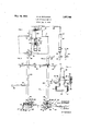
- Figure 1 is a sectional view of a portion of a. tank car, showing the cleansing device of my invention in operative position therein.
- the fluid heating means are shown diagrammatically; and portions of the figure are broken away to reduce its length.
- Fig. 2 is an enlarged side elevation of the cleansing device of Fig. '1. Portions of the figure are broken away to reduce its length.
- Fig. 3 is an enlarged side elevation of the cleansing device, the direction of view being indicated by the arrow 3 of Fig. 2. Portions of the figure are broken away to reduce its 7 length.
- Fig. 4 is a still more highly enlarged view of a portion ofthe device showing thecon nection between the rotatable head and the stationary support therefor, as well as the means for retarding rotation'of the head.
- My invention comprises the provision of a device capable of thoroughly cleansing the interior of such receptacles as tank cars, without the necessity of employing detergents,
- a portion of my invention comprises the provision of a plurality of such jets rotating at a predetermined'speed so 'as to strike the entire interior surface of the container.
- a tank 11 such as that commonly employed by tank cars for the transportation of liquids and semi-liquids of various characters.
- tanks 11 are commonly supplied with a dome 12 having an aperture or manhole 13 permitting access to the interior of the tank; and a ladder 14 is frequently permanently attached to the tank 11 to facilitate entrance to the tank.
- An outlet 16 is provided, through which the tank 11 may be drained, it being understood that the outlet 16 may be closed by any suitable type of valve (not shown).
- One portion of my cleaning device oomprises a spider 21 adapted to be positioned upon the top of the dome 12 over the'manhole 13.
- Each of the arms 22 of the spider is'provided with a flange 23 extending downwards 13 and retain the spider 21 centrally thereof.
- a fluid-conducting pipe 24 is slidabl'e within a central aperture through the spider 21, permitting vertical adjustment of'the pipe 24 in respect thereto.
- the pipe 24 is adapted to be connected by a conduit 26, to the outlet end 27 of a mixing chamber 28; and a water pipe 29 and a steam pipe 31 are adapted to discharge into the mixing. chamber 28.
- valves 32 and 33 respectively, by means of which the flow of water and steam to the mixing chamber 28 may be controlled. This provides a convenient and eflicacious-means for heating water to be supplied'to the cleansing. device.
- An adjustable bracket 34 is secured to' the pipe 24, preferably adjacent its lower end;
- a head indicated in its entirety at 37 is revolubly mounted upon the lower end 38 of the pipe 24.
- a bell reducer 39 is threaded to the lower end 38 of the pipe 24, ahd has a nipple 41 threaded into its lower end.
- the internal diameter of the nipple 41 is sufliciently less than thatof the lower end of the bell reducer therefrom to engage the sides of the manhole.
- the head 37 comprises a T-fitting 43 into i vided by the nipple 41.
- the head 37 is permitted rotary move- .ment in respect to the pipe 24, but is withheld against moving longitudinally thereof.
- An L-fitting 51 is threaded into each of the runs 52 of'the T-fittingl'43; and a nozzle 53 is threaded into the outlet of each of the Us 51.
- the Ls are turned so that their nozzles are directed toward opposite sides of a diameter of the pipe 24, with the resultthat the nozzles 53 are directed tangentially in respect to the axis of rotation of the head 37, so that when fluid is forced through the nozzles 53, the counta'thrust from the jets, rotates the head 37 in a plane perpendicular to the axis of the pipe 24.
- the degree of angularity of the nozzles 53 Withthe plane of rotation. of the head 37 may be varied so as to direct the jets of the two nozzles to different portions of the interior of the tank.
- each of the L-fittings 51 is also provided with an auxiliary nozzle
- each of the nozzles 66 is made up of a tip 67 and a plurality of pipe fittings 68, so that the nozzles 66 can be directed in predetermined direction.
- a steam line 71 adapted to extend into the tank 11 through the manhole 13 and supply the interior ofthe tank 11 with steam, at the same time that the cleansing deviceabove described is being employed.
- the pipe 71 is provided with a plurality of sets 72 and 73 of nozzles 74 and 76 respectively, adapted to direct the steam in. all directions within the tank 11.
- the revolving head 37 is positioned within the tank 11 to-be cleaned and held rigid-therein by means of the spider 21 and bracket 34.
- the steam pipe-71 is then positioned, and steam supplied thereto to raise the temperature of the tank 11 and render more fluid-the remainder of the contents of the tank, which it.is desired to remove.
- the reaction from the nozzles will result in the rotation of the head 37 in a horizontal plane, and the speed of this rotation may be predetermined by properly position.- ing the nuts 62 and 63 to impose the desired degree of spring tension uponQthe planetary gear 57.
- the nozzles'53 are provided with orifices which are elongated to deliver flat jets of high velocity, since I have found by experimentation that this type of jet has the maximum scrubbingaction.
- a tank cleaner a fixed member and a rotatable member, a nozzle arranged tangentially upon said rotatable member, means for supplying fluid under pressure to said nozzle, a gear fixed to one of said members, a gear revolubly mounted uponthe other member and enmeshed with the fixed gear, and means for retarding the rotation of said revolubly mounted gear.
- a tank cleaner a fluid-conducting pipe, a head revolubly mounted upon'the pipe, a nozzle carried by the head and directed tangentially thereof, there being a passageway through the head establishing communication between the pipe and the nozzle, a gear mounted coaxially upon said pipe, a gear mounted upon said head eccentrically of and enmeshed with said first mentioned gear, one
- a fluid-conducting pipe a head revolubly mounted upon the pipe, a nozzle carried bythe head and directed tangentially thereof, there being a passageway'through the head establishing communication between the pipe and the nozzle, a gear fixed coaxially to said pipe, a gear enmeshed with said fixed gear and journalled on said head ec'centrically in respectto said fixed gear, and means for retarding the rotation ofsaid second mentioned gear.”
- a tank cleaner In a tank cleaner, a fluid-conducting pipe, a head revolubly mounted upon the pipe,
- a nozzle carried by the head anddirected tangentially thereof, there being a passageway through the head establishing communication between the pipe and the nozzle, a
- a tank cleaner a fluid-conducting pipe, a head revolubly mounted upon the pipe, a nozzle carried by the head and di rected tangentially thereof, there being apassageway through the head establishing communication between the pipe and the nozzle, a gear fixed coaxially to saidpipe, an
- nozzles being disposed at different degrees of fingslilaritygwith the axis of rotation of the 7.
- a fluid-conducting pipe a' head revolubly mounted upon the pipe, a nozzle carried by the head and directed tangentially thereof, there being a passageway through the head establishing communication between the pipe and the nozzle, a gear fixed coaxially to said pipe, an arm rigid with said head, a planetary gear journalled upon said arm and enmeshed with said fixed gear, and a secondary nozzle arranged tangentially upon said head to direct its jet rearwards in respect to the direction of rota- 5v tion of the head, said nozzles being disposed at difi'erent degrees of angularity with the am's of rotation of the head.
- a tank cleaner comprising a fluid-conducting pipe, said pipe having an annular 1o shoulder extending inwards adjacent its end, a sleeve revoluble in respect to said pipe and having a complementary shoulder in engagement with the first mentioned shoulder, a T fitting carried by said sleeve, an L-shaped nozzle secured to each of the runs of the T- fitting, a gear rigid with the pipe and arranged coaxially thereof, an arm rigid with the T-fitting, a planetary gear journalled upon said arm and enmeshed with the first mentioned gear, a nut threaded on said arm, and a spring under compression between said nut and said planetary gear.
- a tank cleaner 2. fluid-conducting pipe, a head revolubly mounted upon the ,25 pipe, nozzles carried by the head and directed tangentially thereof, there being a pas- 'sageway through the head establishing communication between the pi e and the nozzles, a gear fixed coaxially to said pipe, a gear enmeshed with said fixed gear and carried by said head for planetary movement about the fixed gear, and means foiretarding the rotation of" said planetary gear, said nozzles being adjustable in respect to the headto 3 var the degree of a'ngularity of said nozzles 1 wit the plane of rotation of said head.
Landscapes
- Engineering & Computer Science (AREA)
- Mechanical Engineering (AREA)
- Cleaning In General (AREA)
Description
May 10, 1932. w. E. PETERSON TANK CLEANING DEVICE Filed Aug. 8, 1928 INVENTOR w. E. PETERSON AT TOR NEYS Patented I May 10, 1932 I UNIT-EDT ST'ATES PATEjNT omen warm 1:. rnraason, or meLEwoon, caruoamn, assmnon. or onE-mmn 'ro JOSEPH v. PALMER, or namrosa B ACH, CALIFORNIA ranx eta-mine DEVICE Appllcdtion filed August a, 1928. swarm. 298,259.
This invention relates to tank-cleaning dev s An ob'ect of the invention'i's the provision of'a tan -cleaning device adapted to e-fli'ec 5 tively cleanse the inside of receptacles of various types, but which is. particularly adapted for cleaning the inside of tank cars such as those used for transporting petroleum and its derivatives. a A more detailed object is the provision of V a tank-cleaning device comprising a plurality of nozzles arranged tangentially and journalled upon a fluid-conducting pipewhich is adapted to be positioned with the head disposed within the-tank. Thus when fluid is supplied to the pipe under. pressure, the head" W1 be rotated upon the pipe, with the result that the jets from the nozzles,'travel in c1r-' 'cular paths therearound, strikin the walls of the tank to efl'ectually'cleanse t em. .A further object is the provision of a cleaning device as described, provided with means for retarding the speed of rotation of the head so as to gain the maximumicleansing efliciency of the jets.
A further object is the provision of a cleaning device as described, wherein the jets are capable of adjustment to var their degree of angularity w1th the plane 0 rotation of the head, so that all'portions of the interior of the tank may be cleaned.
A still further object is the provision of a cleaning device having a nozzle adapted to direct fluid against the interior of the tank, and a mixing chamber in communication with the nozzle wherein water and steam may be combined to raise the temperature of the water supplied to the nozzle, so that the cleansing efficiency of the jet may be increased.
' A still further object is the provision of means for warming the interior of the tank during the cleansing process, so that such materials as crude oil may be reduced in tenacity to permit more ready removal thereof from the interior of the tank.
The invention possesses other objects and advantageous features, some of which, with these enumerated, will be set forth in the following description or the inventions part cular embodiment which is illustrated in the drawings accompanying and forming a part of the specification.
The form of'construction herein disclosed, has in actual use, proven to be very efficient, capable of facile and rapid operation, and generally desirable in other respects. For these reasons, the details herein disclosed may be considered as preferred. It should be mentioned however, that whilethese details will hereinafter be specifically described, variations may be efi'ected within the scope of the invention as claimed.
' Referring to the'drawings:
Figure 1 is a sectional view of a portion of a. tank car, showing the cleansing device of my invention in operative position therein. The fluid heating means are shown diagrammatically; and portions of the figure are broken away to reduce its length. I
Fig. 2 is an enlarged side elevation of the cleansing device of Fig. '1. Portions of the figure are broken away to reduce its length.
Fig. 3 is an enlarged side elevation of the cleansing device, the direction of view being indicated by the arrow 3 of Fig. 2. Portions of the figure are broken away to reduce its 7 length.
' .Fig. 4 is a still more highly enlarged view of a portion ofthe device showing thecon nection between the rotatable head and the stationary support therefor, as well as the means for retarding rotation'of the head.
My invention comprises the provision of a device capable of thoroughly cleansing the interior of such receptacles as tank cars, without the necessity of employing detergents,
chemicals, or the like. While it is herein described in connectionwith a tank car, I wish it to be understood that thedevice is also of utility when employed for cleansing the interior of other receptacles. Its use in connection with tank cars is described, because of the fact that the cleansing of the interior of such containers oftentimes is a problem diflicult of solution, owing to the fact that these cars are used in the transportation of crude oil and its derivatives, and other substances ex-' ceedingly tenacious and difiicult to remove from any surface with in contact.
I have found it expedient to provide means for raising the temperature of the tank and those portions of the contents thereof which it is desirable to remove from the tank, until the material-becomes sufliciently fluid to permit washing thereof by high-velocity jets of hot water. A portion of my invention comprises the provision of a plurality of such jets rotating at a predetermined'speed so 'as to strike the entire interior surface of the container. v
With this broad conception of the invention in view, I have described the device as employed for cleansing the interior of a tank 11 such as that commonly employed by tank cars for the transportation of liquids and semi-liquids of various characters. These which they have come tanks 11 are commonly supplied with a dome 12 having an aperture or manhole 13 permitting access to the interior of the tank; and a ladder 14 is frequently permanently attached to the tank 11 to facilitate entrance to the tank. An outlet 16 is provided, through which the tank 11 may be drained, it being understood that the outlet 16 may be closed by any suitable type of valve (not shown). I
. One portion of my cleaning device oomprises a spider 21 adapted to be positioned upon the top of the dome 12 over the'manhole 13. Each of the arms 22 of the spider, is'provided with a flange 23 extending downwards 13 and retain the spider 21 centrally thereof. A fluid-conducting pipe 24 is slidabl'e within a central aperture through the spider 21, permitting vertical adjustment of'the pipe 24 in respect thereto. The pipe 24 is adapted to be connected by a conduit 26, to the outlet end 27 of a mixing chamber 28; and a water pipe 29 and a steam pipe 31 are adapted to discharge into the mixing. chamber 28. The,
An adjustable bracket 34 is secured to' the pipe 24, preferably adjacent its lower end;
and has a pair of fingers 35 dependent from its outer end adapted to engage one of the rungs 36 of the ladder 14 to brace the'pipe 24 and hold it rigidly against inadvertent displacement. A head indicated in its entirety at 37 is revolubly mounted upon the lower end 38 of the pipe 24. For the support of .this head 37, a bell reducer 39 is threaded to the lower end 38 of the pipe 24, ahd has a nipple 41 threaded into its lower end. The internal diameter of the nipple 41 is sufliciently less than thatof the lower end of the bell reducer therefrom to engage the sides of the manhole.
39, to provide a shoulder- 42 for the support of the head 37 ,The head 37 comprises a T-fitting 43 into i vided by the nipple 41. Thus it may be seen that the head 37 is permitted rotary move- .ment in respect to the pipe 24, but is withheld against moving longitudinally thereof.
An L-fitting 51 is threaded into each of the runs 52 of'the T-fittingl'43; and a nozzle 53 is threaded into the outlet of each of the Us 51. The Ls are turned so that their nozzles are directed toward opposite sides of a diameter of the pipe 24, with the resultthat the nozzles 53 are directed tangentially in respect to the axis of rotation of the head 37, so that when fluid is forced through the nozzles 53, the counta'thrust from the jets, rotates the head 37 in a plane perpendicular to the axis of the pipe 24.
By turning the L-fittings 51 within their respective runs of the T-fitting 43, the degree of angularity of the nozzles 53 Withthe plane of rotation. of the head 37, may be varied so as to direct the jets of the two nozzles to different portions of the interior of the tank.
Since the tangential arrangement of the nozzle 53 results in rotating the head 37 at a relatively high rate of speed, I have found that the efliciency of the device is increased if means are provided for retarding the rotation of the head .37. One effective means of accomplishing this end is to mount agear 56 rigidly upon the nipple 41 in position to be enmeshed with a planetary gear 57 j ournalled upon an arm 58 which is sequred to the T- fitting 43, so that as the head 37 rotates, the gear 57 travels about the gear 56 in planetary motion. The gear 57 rests upon a shoulder 59 and is engaged by a spring 61 which is under compression between the gear 57 and 58 to alter the degree of compression of the spring 61. A lock=nut 63 is also threaded upon the arm 58 above the nut 62, to lock the parts in adjusted position against inadvertent displacement. 1
Each of the L-fittings 51 is also provided with an auxiliary nozzle Preferably each of the nozzles 66 is made up of a tip 67 and a plurality of pipe fittings 68, so that the nozzles 66 can be directed in predetermined direction. However, it is desirable that they point in the opposite direction from that of the associated primary nozzle 53 in respect to the direction ofrotation of the head 37, so thatv they aid in retarding rotation of the head 37 as well as in washing those portions of the interior of the tank 11 which are not reached by the jets from the primary nozzles 53.
Since oftentimes the tanks 11 to be cleansed, have contained Viscous and sticky materialssuch as crude oil, the cleaning thereof is facilitated by raising the temperature Within the tanks until the material is in a more fluid state. Accordingly, I have provided a steam line 71 adapted to extend into the tank 11 through the manhole 13 and supply the interior ofthe tank 11 with steam, at the same time that the cleansing deviceabove described is being employed. The pipe 71 is provided with a plurality of sets 72 and 73 of nozzles 74 and 76 respectively, adapted to direct the steam in. all directions within the tank 11. v
It is believed that the operation of my improved tank-cleaning device is readily under stood from the above description of the constituent parts thereof. The revolving head 37 is positioned within the tank 11 to-be cleaned and held rigid-therein by means of the spider 21 and bracket 34. The steam pipe-71 is then positioned, and steam supplied thereto to raise the temperature of the tank 11 and render more fluid-the remainder of the contents of the tank, which it.is desired to remove.
Then, by opening the valves 32 and 33, cold water and steam maybe admitted to the mixing chamber 28, with the result that the water v ings of the Valves.
may be heated to any desired de 'ee of temperature, depending u on the re ative openhus hot water under. pressure is supplied to the head 37 to be eject.-
i ed from the nozzles 53 and 66. As above'described, the reaction from the nozzles will result in the rotation of the head 37 in a horizontal plane, and the speed of this rotation may be predetermined by properly position.- ing the nuts 62 and 63 to impose the desired degree of spring tension uponQthe planetary gear 57.
In their preferable form, the nozzles'53 are provided with orifices which are elongated to deliver flat jets of high velocity, since I have found by experimentation that this type of jet has the maximum scrubbingaction.
I claim:
1. In a tank cleaner, a fixed member and a rotatable member, a nozzle arranged tangentially upon said rotatable member, means for supplying fluid under pressure to said nozzle, a gear fixed to one of said members, a gear revolubly mounted uponthe other member and enmeshed with the fixed gear, and means for retarding the rotation of said revolubly mounted gear.
' 2. In a tank cleaner, a fluid-conducting pipe, a head revolubly mounted upon'the pipe, a nozzle carried by the head and directed tangentially thereof, there being a passageway through the head establishing communication between the pipe and the nozzle, a gear mounted coaxially upon said pipe, a gear mounted upon said head eccentrically of and enmeshed with said first mentioned gear, one
of said gears being fixed against rotation upon its supporting structure, and means for retarding the rotation of'the other gear.
3. In atank cleaner, a fluid-conducting pipe, a head revolubly mounted upon the pipe, a nozzle carried bythe head and directed tangentially thereof, there being a passageway'through the head establishing communication between the pipe and the nozzle, a gear fixed coaxially to said pipe, a gear enmeshed with said fixed gear and journalled on said head ec'centrically in respectto said fixed gear, and means for retarding the rotation ofsaid second mentioned gear.".
In a tank cleaner, a fluid-conducting pipe, a head revolubly mounted upon the pipe,
a nozzle carried by the head anddirected tangentially thereof, there being a passageway through the head establishing communication between the pipe and the nozzle, a
gear fixedcoaxially to said pipe, an arm rigid with said head, a planetary gearjour nalled upon said arm and enmeshed with said fix'ed gear, and means for retarding rotation of sai planetary gear upon the arm.
5. In a tank cleaner, a fluid-conducting pipe, a head revolubly mounted upon the pipe, a nozzle carried by the head and di rected tangentially thereof, there being apassageway through the head establishing communication between the pipe and the nozzle, a gear fixed coaxially to saidpipe, an
arm ri id with said head, a planetary gear journa ed upon said arm and enmeshed with said fixed gear, a nut threaded upon saidarm, and a spring under compression between said planetary gear and said nut.
.6. In a tank cleaner, a fluid-conducting,
pipe, a head revolubly mounted u on the pipe, a nozzle carried by the head all directed tangentially thereof, there being apas-u .sageway through the head establishmg communication between the pipe and the nozzle, a gear fixed'coaxially to said. pipe, a gear enmeshed with said fixed gear. and rotatably carried by'said head for planetary movement about the fixed gear, means for retarding the rotation of said planetary gear, and a secondary nozzle arranged tangentially upon saidhead to direct its jet rearwards in respect to the direction of rotation of the head, said;
nozzles being disposed at different degrees of fingslilaritygwith the axis of rotation of the 7. In a tank cleaner, a fluid-conducting pipe, a' head revolubly mounted upon the pipe, a nozzle carried by the head and directed tangentially thereof, there being a passageway through the head establishing communication between the pipe and the nozzle, a gear fixed coaxially to said pipe, an arm rigid with said head, a planetary gear journalled upon said arm and enmeshed with said fixed gear, and a secondary nozzle arranged tangentially upon said head to direct its jet rearwards in respect to the direction of rota- 5v tion of the head, said nozzles being disposed at difi'erent degrees of angularity with the am's of rotation of the head.
8. A tank cleaner comprising a fluid-conducting pipe, said pipe having an annular 1o shoulder extending inwards adjacent its end, a sleeve revoluble in respect to said pipe and having a complementary shoulder in engagement with the first mentioned shoulder, a T fitting carried by said sleeve, an L-shaped nozzle secured to each of the runs of the T- fitting, a gear rigid with the pipe and arranged coaxially thereof, an arm rigid with the T-fitting, a planetary gear journalled upon said arm and enmeshed with the first mentioned gear, a nut threaded on said arm, and a spring under compression between said nut and said planetary gear.
9. In a tank cleaner, 2. fluid-conducting pipe, a head revolubly mounted upon the ,25 pipe, nozzles carried by the head and directed tangentially thereof, there being a pas- 'sageway through the head establishing communication between the pi e and the nozzles, a gear fixed coaxially to said pipe, a gear enmeshed with said fixed gear and carried by said head for planetary movement about the fixed gear, and means foiretarding the rotation of" said planetary gear, said nozzles being adjustable in respect to the headto 3 var the degree of a'ngularity of said nozzles 1 wit the plane of rotation of said head.
In testimony whereof I have signed my name to this specification. WALTER E. PETERSON. 4
Priority Applications (1)
| Application Number | Priority Date | Filing Date | Title |
|---|---|---|---|
| US298259A US1857766A (en) | 1928-08-08 | 1928-08-08 | Tank cleaning device |
Applications Claiming Priority (1)
| Application Number | Priority Date | Filing Date | Title |
|---|---|---|---|
| US298259A US1857766A (en) | 1928-08-08 | 1928-08-08 | Tank cleaning device |
Publications (1)
| Publication Number | Publication Date |
|---|---|
| US1857766A true US1857766A (en) | 1932-05-10 |
Family
ID=23149738
Family Applications (1)
| Application Number | Title | Priority Date | Filing Date |
|---|---|---|---|
| US298259A Expired - Lifetime US1857766A (en) | 1928-08-08 | 1928-08-08 | Tank cleaning device |
Country Status (1)
| Country | Link |
|---|---|
| US (1) | US1857766A (en) |
Cited By (14)
| Publication number | Priority date | Publication date | Assignee | Title |
|---|---|---|---|---|
| US2954038A (en) * | 1958-05-28 | 1960-09-27 | Jack L Girard | Spinner for cleaning tanks |
| US3070103A (en) * | 1958-07-28 | 1962-12-25 | Continental Aviat & Eng Corp | Bearing treating apparatus |
| US3529611A (en) * | 1968-03-15 | 1970-09-22 | Delta Mfg & Eng Corp | Vehicle washing apparatus |
| EP0247532A3 (en) * | 1986-05-26 | 1988-11-09 | Helmut Becker | Cleaning device for containers and the like |
| US4923120A (en) * | 1988-04-12 | 1990-05-08 | Paul Hammelmann | Nozzle device |
| US4941493A (en) * | 1988-08-15 | 1990-07-17 | Carry Companies Of Illinois | Device for washing and drying the inside tank of a tanker truck |
| US5301702A (en) * | 1992-09-28 | 1994-04-12 | Mckinney Robert D | Tank power jet assembly |
| US6321754B1 (en) * | 1998-01-21 | 2001-11-27 | Taiho Industries Co., Ltd. | Tank washing apparatus and method |
| US20020144714A1 (en) * | 2001-04-04 | 2002-10-10 | Mccasker Douglas Brett | Rotary cleaning apparatus |
| WO2007021190A3 (en) * | 2005-08-17 | 2007-04-19 | Anro Spray Solutions | Spray assembly for spraying foam and liquid for cleaning a surface and also a cleaning installation and method |
| US9656308B2 (en) | 2015-07-10 | 2017-05-23 | NGL Solids Solutions, LLC | Systems and processes for cleaning tanker truck interiors |
| US9925572B2 (en) | 2015-07-10 | 2018-03-27 | NGL Solids Solutions, LLC | Devices, systems, and processes for cleaning the interiors of frac tanks |
| US10589287B2 (en) | 2015-07-10 | 2020-03-17 | NGL Solids Solutions, LLC | Systems and methods for oil field solid waste processing for re-injection |
| US11911732B2 (en) | 2020-04-03 | 2024-02-27 | Nublu Innovations, Llc | Oilfield deep well processing and injection facility and methods |
-
1928
- 1928-08-08 US US298259A patent/US1857766A/en not_active Expired - Lifetime
Cited By (17)
| Publication number | Priority date | Publication date | Assignee | Title |
|---|---|---|---|---|
| US2954038A (en) * | 1958-05-28 | 1960-09-27 | Jack L Girard | Spinner for cleaning tanks |
| US3070103A (en) * | 1958-07-28 | 1962-12-25 | Continental Aviat & Eng Corp | Bearing treating apparatus |
| US3529611A (en) * | 1968-03-15 | 1970-09-22 | Delta Mfg & Eng Corp | Vehicle washing apparatus |
| EP0247532A3 (en) * | 1986-05-26 | 1988-11-09 | Helmut Becker | Cleaning device for containers and the like |
| US4923120A (en) * | 1988-04-12 | 1990-05-08 | Paul Hammelmann | Nozzle device |
| US4941493A (en) * | 1988-08-15 | 1990-07-17 | Carry Companies Of Illinois | Device for washing and drying the inside tank of a tanker truck |
| US5301702A (en) * | 1992-09-28 | 1994-04-12 | Mckinney Robert D | Tank power jet assembly |
| US6321754B1 (en) * | 1998-01-21 | 2001-11-27 | Taiho Industries Co., Ltd. | Tank washing apparatus and method |
| US20020144714A1 (en) * | 2001-04-04 | 2002-10-10 | Mccasker Douglas Brett | Rotary cleaning apparatus |
| US6868857B2 (en) * | 2001-04-04 | 2005-03-22 | Mccasker Douglas Brett | Rotary cleaning apparatus |
| WO2007021190A3 (en) * | 2005-08-17 | 2007-04-19 | Anro Spray Solutions | Spray assembly for spraying foam and liquid for cleaning a surface and also a cleaning installation and method |
| US20110048470A1 (en) * | 2005-08-17 | 2011-03-03 | Anro Spray Solutions | Spray Assembly for Spraying Foam and Liquid for Cleaning a Surface and Also a Cleaning Installation and Method |
| US9656308B2 (en) | 2015-07-10 | 2017-05-23 | NGL Solids Solutions, LLC | Systems and processes for cleaning tanker truck interiors |
| US9925572B2 (en) | 2015-07-10 | 2018-03-27 | NGL Solids Solutions, LLC | Devices, systems, and processes for cleaning the interiors of frac tanks |
| US9925573B2 (en) | 2015-07-10 | 2018-03-27 | NGL Solids Solutions, LLC | Systems and processes for cleaning tanker truck interiors |
| US10589287B2 (en) | 2015-07-10 | 2020-03-17 | NGL Solids Solutions, LLC | Systems and methods for oil field solid waste processing for re-injection |
| US11911732B2 (en) | 2020-04-03 | 2024-02-27 | Nublu Innovations, Llc | Oilfield deep well processing and injection facility and methods |
Similar Documents
| Publication | Publication Date | Title |
|---|---|---|
| US1857766A (en) | Tank cleaning device | |
| US5301702A (en) | Tank power jet assembly | |
| US5409027A (en) | Apparatuses for cleaning paint rollers through plural sprays which turn and clean supported rollers | |
| US620224A (en) | Tube-washing apparatus | |
| US3121536A (en) | Tank cleaning apparatus | |
| US5638845A (en) | Scissor jet cleaning device | |
| US1557240A (en) | Tank cleaner and fluid circulator | |
| US3073325A (en) | Drum washer | |
| US1447305A (en) | Dishwashing device | |
| US1314622A (en) | of milwaukee | |
| US1298973A (en) | Milk-can cleaning and spraying device. | |
| US1561809A (en) | Hydraulic washing apparatus | |
| US2691549A (en) | Cleaning machine | |
| US2785008A (en) | Tank-cleaning device | |
| US2190576A (en) | Wall cleaning apparatus | |
| US1218936A (en) | Tumbler and bottle washer. | |
| CN220678869U (en) | Automatic cleaning device for reaction kettle tank body in chemical and pharmaceutical industry | |
| JPH04215881A (en) | Washing nozzle | |
| US2030194A (en) | Tank washing and watering device | |
| US1831029A (en) | Tank car washer | |
| US1174336A (en) | Soap-supplying device for glass-washers. | |
| CN210230922U (en) | Multi-angle adjustable tank washer | |
| SU488632A1 (en) | Tank cleaning device | |
| SU422480A1 (en) | DEVICE FOR WASHING THE INTERNAL SURFACE OF CAPACITIES | |
| US1547545A (en) | High-pressure washing machine |