US1857760A - Electric railway system - Google Patents
Electric railway system Download PDFInfo
- Publication number
- US1857760A US1857760A US168189A US16818927A US1857760A US 1857760 A US1857760 A US 1857760A US 168189 A US168189 A US 168189A US 16818927 A US16818927 A US 16818927A US 1857760 A US1857760 A US 1857760A
- Authority
- US
- United States
- Prior art keywords
- wire
- motor
- track
- truck
- controlling
- Prior art date
- Legal status (The legal status is an assumption and is not a legal conclusion. Google has not performed a legal analysis and makes no representation as to the accuracy of the status listed.)
- Expired - Lifetime
Links
- 230000001276 controlling effect Effects 0.000 description 60
- 239000004020 conductor Substances 0.000 description 5
- 230000007935 neutral effect Effects 0.000 description 2
- 230000001105 regulatory effect Effects 0.000 description 2
- 101100294184 Mus musculus Ninl gene Proteins 0.000 description 1
- 238000010276 construction Methods 0.000 description 1
- 230000005484 gravity Effects 0.000 description 1
- 230000000979 retarding effect Effects 0.000 description 1
- 238000004804 winding Methods 0.000 description 1
Images

Classifications
-
- B—PERFORMING OPERATIONS; TRANSPORTING
- B60—VEHICLES IN GENERAL
- B60L—PROPULSION OF ELECTRICALLY-PROPELLED VEHICLES; SUPPLYING ELECTRIC POWER FOR AUXILIARY EQUIPMENT OF ELECTRICALLY-PROPELLED VEHICLES; ELECTRODYNAMIC BRAKE SYSTEMS FOR VEHICLES IN GENERAL; MAGNETIC SUSPENSION OR LEVITATION FOR VEHICLES; MONITORING OPERATING VARIABLES OF ELECTRICALLY-PROPELLED VEHICLES; ELECTRIC SAFETY DEVICES FOR ELECTRICALLY-PROPELLED VEHICLES
- B60L15/00—Methods, circuits, or devices for controlling the traction-motor speed of electrically-propelled vehicles
- B60L15/32—Control or regulation of multiple-unit electrically-propelled vehicles
-
- B—PERFORMING OPERATIONS; TRANSPORTING
- B60—VEHICLES IN GENERAL
- B60L—PROPULSION OF ELECTRICALLY-PROPELLED VEHICLES; SUPPLYING ELECTRIC POWER FOR AUXILIARY EQUIPMENT OF ELECTRICALLY-PROPELLED VEHICLES; ELECTRODYNAMIC BRAKE SYSTEMS FOR VEHICLES IN GENERAL; MAGNETIC SUSPENSION OR LEVITATION FOR VEHICLES; MONITORING OPERATING VARIABLES OF ELECTRICALLY-PROPELLED VEHICLES; ELECTRIC SAFETY DEVICES FOR ELECTRICALLY-PROPELLED VEHICLES
- B60L2200/00—Type of vehicles
- B60L2200/26—Rail vehicles
Definitions
- Fig. 2 is a wiring plan for a pair of trucks and has certain features that are peculiar to coupled together; electric railways, other features that are Fig. 3 is a developed wiring d agram of peculiar to railroads operated automatically three coupled trucks forming a train and still other features that are of general 1g. 4 shows a coupled two car train using 5 application in thefart of railroading or the lnlt trucks. trans )ortation of rei ht.
- Wire 21 id constmctlon 111 Whlch h Car trucks are is energized through a resistance 20 from the separate from the carbodies and througlrthe power Wire 13 and at the end of each block car bodies these trucks may be coupled into these Wires 21 and 22 are connected by the a train.
- the trucks are provided with elecjumper 23
- the length of the blocks may he ninL' direction of the motors may be remotely mined by the jumper 23 Without materially controlled for the direction of running deadding to the cost.
- the power wire The trucks are provided with a oralnng 13 and the block Wires 21 and 22 may he Sup Y- -Q automatically p d y P ported by an overhead construction to engage pulsion motors. as fully described 111 U. S. trolleys on thetop of the trucks;however,afiy 40 Patent 13053551 lsslled y other location may be used for these conduc- T 11959 oblects are more l fi y tors.
- Fig. 1 is a track layout showing the ap- 14. which is adjustable, is interposed on the l w hlication of the block system power wire between blocks t and g causing a y a I a voltage drop on the section 9 and thereby reducing the speed of the train.
- the truck wiring Fig. 3 shows the wiring arrangement for trucks A, B and C coupled into a train.
- the wiring of each truck is identical and similar reference characters are used to designate similar parts.
- the trolley contacts 41 and 42 engage the block wires 22 and 21 and the trolley contact 43 engages the power wire.
- block relay 44 is grounded on one side by wire 47 and on the other'side connects by wire 46 and switch 45 with the trolley 41.
- the trolley- 42 is groundedby wire 84.
- the block system be operated from one point on the train as for instance on the leading car or truck.
- the trolley 41 on car A controls the block relays on the other cars.
- a master controller on each truck controls the operation of the driving motor. When this controller is in one position the driving motor is directly connected in multiple circuit to the power wire, and when the controller is in the opposite position, the motor is connected in series with the motor of an adj oining truck.
- the master controller is indicated by MS. 'When the magnet M is energized the condition of multiple control is established and when the magnet S is energized the condition of series control is established.
- the master controller is directly operated from the power wire by the centrifuge 62 through wire 51, contact 52 of the centrifuge and with the truck at restor traveling below en the net M and to ground on wire 56.
- the S magnets of the adjacent trucks are energized in multiple circuit and are controlled by the centrifuge on one truck. Energizing these magnets places the motors on these trucks A and B in series circuit and their operating current is controlled by the block relay and by the centrifuge which operates the master controller. Truck C with the controlling switch 60 in the neutral position operates by itself and is regulated by its own centrifuge.
- the motor 69 is controlled by two circuits, one of which includes wire 3 and the other includeswire 67 and contact 68, leading from thcpowcr supply wire 64.
- the motor On truck A as shown in Fig. 3 the motor is energized through 73 and 6768 in multiple.
- On truck B wire 7 3 is on open circuit at switch 72 and the motor is energized through 67 and 68 only. The same conditions are established on truck C. It is apparent that when magnet S on truck A is energized the circuit of wire 67 is interrupted at 68 and the motor is energized only by wire 73; also, on truck B when magnet S is energized the circuit of 67 is interrupted at 68.
- Vhen magnet M is energized the master controller is in the position shown.
- truck A the power to the motor is controlled by the block relay 44, wire 64. resistance 65. centrifuge contact- 66, wire 67. contact finger 68, motor 69, contact finger 7.1. and wire 56 to ground.
- the motor on truck B is controlled by a similar circuit, having similar reference characters and controlled by the block relay 44 and the centrifuge 62 on truck B. It will thus be observed that when the motors are operating in series the master controllers are controlled in multiple circuitby one centrifuge and the current to the coupled motors is controlled by one centrifuge.
- the master controllers are donnected inimultiple circuit and are controlled by one centrifuge while the current to jeach motor is controlled independently by its own block relay and centrifuge. It should be noted that the motors in both se “es and multiple operation are always controlled by their own master controller.
- the block relays 44 are energized by wire 48 from the leading car gas hereinbefore referred to.
- each truck is an independent umt and these trucks are coupled into a train by the car bodies D and E. It is intended that these trucks may be coupled for series or multiple operation with the adjacent motor trucks on either side of them and without regard to direction. That is, a motor truck may be uncoupled from a i train going in one direction and coupled into atrain going in the opposite direction without turning about on the track.
- This arrangement is secured by the uniform circuits and the uniform location of the wiring through the couplers insuring proper connections between thetrucks under all conditions of operation.
- the order of the wires 48, 57. 53 and 76 between the couplers 50 is uniform throughout. stance. the wires 48. 57. 53 and 76 'arelocated in the same order relative to each other, between trucks A and B as between trucks B and C so that the truck C might be cou- For in ing the arrangement of the operating circuits.
- the master switch 60 is placed in the central position as on truck C which isolates this truck from the adjacent trucks except for the block control.
- magnet M of the master controller is energized from wire 51 through switch 54 and wire 55; and the motor is energized from wire 64 controlled by block relay 44, wire 67 controlled by the centrifuge, contact finger 68, motor (59, contact finger 71 and wire 56 to ground.
- This wiring is uniform with the wiring of trucks A and B and is similarly referenced.
- Truck O can be coupled for series or multiple operation with an adjacent truck by the proper manipulation of switch 60. It should be noted in the circuits described, that. wire 56 is a grounded common wire, that is, it is grounded through the truck on the running rail and thus completes the return circuit to the generator 16. y
- a gravity braking system 81 operated by motor- 69 is provided for trucks as disclosed ,in my.
- a plug outlet 99 is provided on wire 64 from the block relay for supplying local current to the motors at a station stop where the power wire is omitted. In this case a cable connected with a current supply is plugged into 99 to move the cars to the position desired.
- the series-multiple control "differs from Fig. 3 by reversing the position ofnvires 53 and 57 as controlled by finger 52 ofthe centrifuge; thus at low speeds multiple control is established and at high speeds series control is established, otherwise the operating circuits are the same in Figs. 2 and 3.
- the direction of running of each motor is determined by the relation of the current in the field winding 70 to the motor armature 69.
- This relay is Connected to the .power wire 51 and is grounded on the truck by wires 47 and 56 and its armature responds to the polarity of the current in the power wire.
- the block wire 84 connects to contact finger 86 of this relay and block wire 83 connects to contact finger 85. In the position shown contact 85 connects to wire 87 and through switch 45 and wire 46 to relay 44, and contact 86 grounds on wires 88 and 56.
- relay 82 is energized by reverse polarity, these contacts change position and wire 84 is connected to block relay 44 and wire 83 is grounded. This adjusts the block system for the established direction of running as described in U. S. Patent 1.6l7,402. For instance, the block system shown in Fig.
- contact 85 grounds wire 83 and shoe 41 in contact with block wire 21 which thereby deenergizes block wire 22 for the rear block and stops or retards a train in this block by causing-the block relay on this train to be deenergized.
- Relay 82 controls the direction of running of the motor by controlling the direction of the current through the field 70.
- the brushes of motor 69, by wires 73 and a connect to the fingers 90 and 91 respectively of relay 82 and these fingers operate as a pole changer controlling the polarity of the current in wires 92 and 93 which supply the field 70 of the motor and thereby determines the direction of running of the motor.
- the direction of running of the motor is thus remotely controlled by relay 82.
- This invention is capable of application in a variety of forms and with other types of trackway controls and is not to be limited to the specific embodiment selected to illustrate its working principles.
- a track a plurality of trucks coupled to form a train and each embodying a motor and a master controller. said master controllers arranged to control the motors of adjacent trucks in series or in multiple, automatic means for operating said master controllers and means controlled from the trackway controlling the operation of said master controller.
- a track a plurality of trucks coupled to form a train and each embodying a motor and a master controller. said master controllers arranged to control the motors of adjacent trucks in series or in multiple and means responsive to the speed of said trucks for operating said master controllers.
- a track a plurality of trucks coupled to form a train and each embodying a motor and a master controller, said master controllers arranged to control said motors in series or in multiple and means on one of said trucks responsive to speed for operating said master controllers.
- a track a motive unit on said track comprising a plurality of motors, means for connecting said motors for series or in multiple operation. and a centrifuge for operating said means.
- a track a motive unit on said track comprising a plurality of motors, a device for connecting said motors for series or in multi le operation and means responsive to speed or operating said device 15 and for controlling the current to said motors.
- the combination a track, a pair of bodying a motor, a master controller and a centrifuge, means for controlling said master controller by one centrifuge for both trucks and for controllin the current to each motor by the centrifuge located on the same'truck as the motor.
- a trac a plurality of trucks coupled to form a train and each embodying a motor, a master controller and a centrifuge, said master controller controlling said motors in series or in multiple and 30 means whereby one centrifuge controls the current to said motors when operating in series.
- a track a plurality of trucks coupled to form a train and each'embodyinga motor and a master controller, said master controller comprising a magnet which when energized connects the motors for series operation and another magnet which, when eneration and automatically operated means on one of said trucks for selectively energizing said magnets.
- a controlling switch on said vehicle con trolling the circuit of said motor, said switch, when in one position, connecting said motor to operate only in series or in multiple with the motor of the vehicle ahead, and when in the reverse position connecting said motor to operate only in series or in multiple with the motor of the vehicle in the rear and means for automatically operating said switch.
- said switch when in one position, connecting said motor to operate in series or in multiple with the motor of the vehicle ahead, and
- a track comprising a plurality of electric motors, a controlling switch and a master controller controlling the circuits of said motors, said controlling switch selectively controlling said master controller tooperate a pair of said motors in series or in multiple circuit and said controlling switch controlling one of said motors toopcrate by itself.
- each unit controlling the power supply to said units and controlling said braking system and means for continuously controlling said relays from the trackway as the train. moves along the track.
- a powerwire on said track means on each of said motive units connecting with said power wire forsupplying power, to said units, and a relay on each unit controlling the power supply to said units and controlling said braking system, said relays being controlled bination;a-tr'ack, a motive unit on said track comprising a plurality of motors, a master controller for connecting said motors for series or multiple operation. means responsive to-the speed of said unit for operating said master controller and remotely controlled means for operating said vehicle in either direction.
- a controlling switch on said vehicle controlling the circuit of said motor to operate 00- operatively with the motors of the coupled vehicles, remotely controlled means for operating said vehicles in either direction and means on the train controlled by traflic conditions controlling the circuit of said motors.
- a track a motive unit on said track comprising a plurality of electric motors, a controL ling switch and. a master controller co-peratively controlling the circuits of a pair of said motors in series and in multiple, means on-said motive unit for operating said motors in either direction and means on the trackway for controlling said means.
- a master controller co-peratively controlling the circuits of a pair of said motors in series and in multiple, means on-said motive unit for operating said motors in either direction and means on the trackway for controlling said means.
Landscapes
- Engineering & Computer Science (AREA)
- Power Engineering (AREA)
- Transportation (AREA)
- Mechanical Engineering (AREA)
- Electric Propulsion And Braking For Vehicles (AREA)
Description
y 1932' M. H. LOUGHRIDGE 1,857,760
ELECTRIC RAILWAY SYSTEM Filed Feb. 14. 1927 3 Sheets-Sheet l May 10, 1932. M. H. LOUGHRIDGE ELECTRIC RAILWAY SYSTEM Filed Feb. 14, 1927 3 Sheets-Sheet 2 ATTORNEY.
May 10, 1932..
H. LOUGHRIDGE 1,857,760
ELECTRIC RAILWAY SYSTEM Filed Feb. 14, 1927 3 Sheets-Sheet 3 A TTORNEY.
Patented May 10, 1932 1,857,766
UNITED STATES PATIENT OFFICE MATTHEW H. LOUGHRIDG-E, OF BOGOTA, N JERSEY ELECTRIC RAILWAY SYSTEM.
Application filed February 14, 1927. Serial No. 168,189.
This invention relates to railway systems Fig. 2 is a wiring plan for a pair of trucks and has certain features that are peculiar to coupled together; electric railways, other features that are Fig. 3 is a developed wiring d agram of peculiar to railroads operated automatically three coupled trucks forming a train and still other features that are of general 1g. 4 shows a coupled two car train using 5 application in thefart of railroading or the lnlt trucks. trans )ortation of rei ht.
Thi: objects of this invention are to pro The Mack lag/out Vide an improved System 9 unit trucks In Fig. 1, the track rails are 11 and 12. 60 power operated and co-operatively connected, The power wire Which is preferably located a system of series-multiple control automaticentrally between the rails and Over the hats, Cally pf and I On the T for is indicated by 13. This power wire is conamomahcauy f g e mung nected with a D. O generator 16 through the of thet'mmspole changing switch 17 by wire'18 and the 65 T inventiim embodies'a block system return circuit is obtained by wire 19 conwhich automatically secures the spacing of meeting to rail 12 cars or trains on the traclr which is described The track is divided into blocks as indi In I]. Patent 1,617,402, issued Feb. 15. 1927. t d b h letters a to g h h blocks are 20 This l i Cfmtemplates a rallway determined by the wires 21 and 22. Wire 21 id constmctlon 111 Whlch h Car trucks are is energized through a resistance 20 from the separate from the carbodies and througlrthe power Wire 13 and at the end of each block car bodies these trucks may be coupled into these Wires 21 and 22 are connected by the a train. The trucks are provided with elecjumper 23 A train running for instahce to 25 tlic f {91131091113011 Purpose and each the right, requires wire 22 to be energized l a capable f opera and if no train is in the succeeding block this alone of 195mg Coupled 71th other wire will be energized through the resistance trucks, and when so coupled the motors of but if a train in the Succeeding block the coupled tmcks y pe t 1n 521195 grounds wire 21, this practically deenergizes so 1n multlple- A centlllfuge 1S Rrovlded 2 2 in the block in the rear and causes the folfor automatically controlling the series-mullowing train to stop until the succeedinn.
tiple operation of the propulsion motors 210- block has been cleared. b
cording to the speed of the train. The 'nm- The length of the blocks may he ninL' direction of the motors may be remotely mined by the jumper 23 Without materially controlled for the direction of running deadding to the cost.
As shown in the drawings the power wire The trucks are provided with a oralnng 13 and the block Wires 21 and 22 may he Sup Y- -Q automatically p d y P ported by an overhead construction to engage pulsion motors. as fully described 111 U. S. trolleys on thetop of the trucks;however,afiy 40 Patent 13053551 lsslled y other location may be used for these conduc- T 11959 oblects are more l fi y tors. These conductors are herein referred to scribed in the following specification and the as l t d on th t k hi h t i i operation of the invention will be undert d d t i l d any l ti on th i ht f stood by reference to the accompanying drawings illustrating the several features of The speed of the train can be regulated by the invention in detail. I the voltage on the power wire, or by the fre- Dmwqg quenc y of power system where altern ating current usech i or eaample, the reslstance Fig. 1 is a track layout showing the ap- 14. which is adjustable, is interposed on the l w hlication of the block system power wire between blocks t and g causing a y a I a voltage drop on the section 9 and thereby reducing the speed of the train.
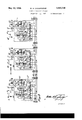
'The truck wiring Fig. 3 shows the wiring arrangement for trucks A, B and C coupled into a train. The wiring of each truck is identical and similar reference characters are used to designate similar parts. The trolley contacts 41 and 42 engage the block wires 22 and 21 and the trolley contact 43 engages the power wire. The
block relay 44 is grounded on one side by wire 47 and on the other'side connects by wire 46 and switch 45 with the trolley 41. The trolley- 42 is groundedby wire 84. When the trolley 41 engages block wire 22 and this wire is en'- er 'zed, the block relay will be energized es;
ta lishing running conditions. Onthe other hand, when the block wire 22 is. deenergized, the block relay is deenergizeddisconnecting the power from the motors and ap lying the brakes as hereinafter described. trolley 42 engages block wire 21,"this wire is grounded, thus deenergizing the block wire 22 in the rear block and thereby stopping a following train. As shown in Figs. 1 and 3 the block s stem operates on the closed circuit plan, ut as described in U. S. Patent 1,617,402, dated Feb. 15, 1927, the same principles can be applied to a block system operating on the open circuit plan.
It is necessary that the block system be operated from one point on the train as for instance on the leading car or truck. As shown in Fig. 3, the trolley 41 on car A controls the block relays on the other cars. On
truck A the switch 45 is closed and a circuit is established in multiple with the block relay 44 to wire 48, which, through the couplers passes fromcar to car through the train connecting with wire 46 on each truck thus placing all the block relays in multiple circuit on the block wire controlled by the trolley 41 on the leading car only. On the following trucks, it will be noted that switch 45 on each truck is opened manually when the trucks are coupled into a train; this switch therefore,
determines the truck from which the block control is made efi'ective.
A master controller on each truckcontrols the operation of the driving motor. When this controller is in one position the driving motor is directly connected in multiple circuit to the power wire, and when the controller is in the opposite position, the motor is connected in series with the motor of an adj oining truck. The master controller is indicated by MS. 'When the magnet M is energized the condition of multiple control is established and when the magnet S is energized the condition of series control is established.
The master controller is directly operated from the power wire by the centrifuge 62 through wire 51, contact 52 of the centrifuge and with the truck at restor traveling below en the net M and to ground on wire 56.
a predetermined speed, through wire 57, switch 58, and wire 59 to magnet S and from there to ground on common wire 56. With the controlling switches 60 in cars A and B he noted, is disconnected at switches 58 and ,54 from trucks A and C.
When magnet-S is energized the contact fingers 68 and 71 of the master controller change to the reverse position from that shown. -Under these conditions the motor is operated from the power wire 51, through contact 63 of the block relay energized, wire 64, resistance 65 Varied by the contact finger 66 of the centrifuge 62, wire 67, switch 72 and wire 7 3 to the terminal of motor 69. The circuit is continued from the opposite terminal of the motor through wire a, contact finger 71, wire 74, switch 75 and wire 76 to switch 7 5 on truck B. On this truck the circuit is continued through wire 74, contact finger 71, motor 69, contact finger 68, wire 77, switch 78 and wire 56 to ground. Thus speed, the S magnets of the adjacent trucks are energized in multiple circuit and are controlled by the centrifuge on one truck. Energizing these magnets places the motors on these trucks A and B in series circuit and their operating current is controlled by the block relay and by the centrifuge which operates the master controller. Truck C with the controlling switch 60 in the neutral position operates by itself and is regulated by its own centrifuge.
With the switches 60 in the position shown in trucks A and B and the centrifuge exceeding a predetermined speed, the circuit of the S magnets is interrupted and the circuit of the M magnets is established. The con tact finger 520i the centrifuge interrupts the connection to wire 57 and establishes connection with wire 53 where the circuit is continued through switch 54, and Wire 55 to mag- The circuit of wire 53 is also continued through the couplers-5O to the truck B and through switch 54 and wire 55energizes magnet M on truck B in multiple circuit with magnet M on truck A. Thus when a predetermined speed is exceeded, magnets M on trucks A and B are energized under the control of the centrifuge 62 on truck A. In order to make, the circuits on each car uniform the motor 69 is controlled by two circuits, one of which includes wire 3 and the other includeswire 67 and contact 68, leading from thcpowcr supply wire 64. On truck A as shown in Fig. 3 the motor is energized through 73 and 6768 in multiple. On truck B wire 7 3 is on open circuit at switch 72 and the motor is energized through 67 and 68 only. The same conditions are established on truck C. It is apparent that when magnet S on truck A is energized the circuit of wire 67 is interrupted at 68 and the motor is energized only by wire 73; also, on truck B when magnet S is energized the circuit of 67 is interrupted at 68.
Vhen magnet M is energized the master controller is in the position shown. ()n truck A the power to the motor is controlled by the block relay 44, wire 64. resistance 65. centrifuge contact- 66, wire 67. contact finger 68, motor 69, contact finger 7.1. and wire 56 to ground. The motor on truck B is controlled by a similar circuit, having similar reference characters and controlled by the block relay 44 and the centrifuge 62 on truck B. It will thus be observed that when the motors are operating in series the master controllers are controlled in multiple circuitby one centrifuge and the current to the coupled motors is controlled by one centrifuge. When the motors are ope ating in multiple, the master controllers are donnected inimultiple circuit and are controlled by one centrifuge while the current to jeach motor is controlled independently by its own block relay and centrifuge. It should be noted that the motors in both se "es and multiple operation are always controlled by their own master controller. The block relays 44 are energized by wire 48 from the leading car gas hereinbefore referred to.
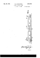
posite position in truck B from that shown in truck A. As shown in Fig. 4 each truck is an independent umt and these trucks are coupled into a train by the car bodies D and E. It is intended that these trucks may be coupled for series or multiple operation with the adjacent motor trucks on either side of them and without regard to direction. That is, a motor truck may be uncoupled from a i train going in one direction and coupled into atrain going in the opposite direction without turning about on the track. This arrangement is secured by the uniform circuits and the uniform location of the wiring through the couplers insuring proper connections between thetrucks under all conditions of operation. As will be noted. the order of the wires 48, 57. 53 and 76 between the couplers 50 is uniform throughout. stance. the wires 48. 57. 53 and 76 'arelocated in the same order relative to each other, between trucks A and B as between trucks B and C so that the truck C might be cou- For in ing the arrangement of the operating circuits.
It is necessary that the motor of a single truck may operate by itself. In this case the master switch 60 is placed in the central position as on truck C which isolates this truck from the adjacent trucks except for the block control. In this case magnet M of the master controller is energized from wire 51 through switch 54 and wire 55; and the motor is energized from wire 64 controlled by block relay 44, wire 67 controlled by the centrifuge, contact finger 68, motor (59, contact finger 71 and wire 56 to ground. This wiring is uniform with the wiring of trucks A and B and is similarly referenced. Truck O can be coupled for series or multiple operation with an adjacent truck by the proper manipulation of switch 60. It should be noted in the circuits described, that. wire 56 is a grounded common wire, that is, it is grounded through the truck on the running rail and thus completes the return circuit to the generator 16. y
The arrangement described is embodied in the car wiring shown in Fig. 2 with the various parts similarly referenced and with some additional features included. A gravity braking system 81 operated by motor- 69 is provided for trucks as disclosed ,in my.
application, Serial No. 7 55,276, filed Sept. 2,
1924. A plug outlet 99 is provided on wire 64 from the block relay for supplying local current to the motors at a station stop where the power wire is omitted. In this case a cable connected with a current supply is plugged into 99 to move the cars to the position desired. The series-multiple control "differs from Fig. 3 by reversing the position ofnvires 53 and 57 as controlled by finger 52 ofthe centrifuge; thus at low speeds multiple control is established and at high speeds series control is established, otherwise the operating circuits are the same in Figs. 2 and 3.
The series-multiple control system described has been illustrated in connection with trucks having one motor each which are suit-ably interconnected to obtain the control specified. It shouldbe understood that the system is applied in a similar manner to trucks in which both motors are mounted on the same truck, as for instance where a motor is applied to each axle of a two axle truck in which case each axle is regarded as a separate truck in this specification.
The direction of running of each motor is determined by the relation of the current in the field winding 70 to the motor armature 69.
The direction of running of the car is rcmotely controlled as fully described in U. S. Patent 1.617.402, dated Feb. 15, 1927, by the pole changing switch 17 of the power supply 16 and the polarized relay 82 on each truck.
This relay is Connected to the .power wire 51 and is grounded on the truck by wires 47 and 56 and its armature responds to the polarity of the current in the power wire. The block wire 84 connects to contact finger 86 of this relay and block wire 83 connects to contact finger 85. In the position shown contact 85 connects to wire 87 and through switch 45 and wire 46 to relay 44, and contact 86 grounds on wires 88 and 56. When relay 82 is energized by reverse polarity, these contacts change position and wire 84 is connected to block relay 44 and wire 83 is grounded. This adjusts the block system for the established direction of running as described in U. S. Patent 1.6l7,402. For instance, the block system shown in Fig. 1 is intended for operation in both directionsthat is, single track operation so that a truck may haveits running direction changed by changing the position of switch 17 and the block system is operative to insure proper spacing of trains when running in either direction. Or again, a truck may be turned around on the track so that the relative positions of wires 83 and 84, Fig. 2 are changed about. It is apparent that the wire which is grounded on 88 and 56, grounds the block wire with which it connects. Thus, wire 84 is grounded as shown and shoe 42 is thereby grounded. If this shoe connects to wire 22 when moving-from right to left, then wire 21 of the rear block is deenergized which causes the deenergizing of the block relay on a following train in the rear block and the stopping or retarding of this train.
If the truck is running in the opposite direction contact 85 grounds wire 83 and shoe 41 in contact with block wire 21 which thereby deenergizes block wire 22 for the rear block and stops or retards a train in this block by causing-the block relay on this train to be deenergized.
Relay 82 controls the direction of running of the motor by controlling the direction of the current through the field 70. The brushes of motor 69, by wires 73 and a connect to the fingers 90 and 91 respectively of relay 82 and these fingers operate as a pole changer controlling the polarity of the current in wires 92 and 93 which supply the field 70 of the motor and thereby determines the direction of running of the motor. The direction of running of the motor is thus remotely controlled by relay 82.
This invention is capable of application in a variety of forms and with other types of trackway controls and is not to be limited to the specific embodiment selected to illustrate its working principles.
Having thus described my invention, I claim:
1. In an electric railway system as de scribed, the combination, a track arranged for electric propulsion, a pluralityof trucks coupled to form a train, each of said trucks embodying a motor unit and uniformly wired, a switch on each truck for connecting the motors of adjacent trucks to operate in series or in multiple and means on one truck controlled from the trackway for automatically controlling the operation of each of said motors.
2. In an electric railway system as described. the combination, a track arranged for electric propulsion, a plurality of trucks coupled to form a train, each ofsaid trucks embodying a motor unit and uniformly wired, a switch on each truck co-operating with a switch on an adjacent truck for connecting the motors of said trucks to operate in series or in multiple and means on one truck controlled from the trackway for automatically controlling the operation of each of said motors.
3. In an electric railway system as described, the combination, a track arranged for electric propulsion, a plurality of trucks coupled to form a train, each of said trucks embodying a motor unit and uniformly wired, a switch on each truck for connecting the motor on the truck to operate by itself or to operate in series or in multiple with the motor of an adjacent truck and means on one truck controlled from the trackway for automatically controlling the operation of said motors when operating in series.
4. In an electric railway system as described. the combination. a track. a plurality of trucks coupled to form a train and each embodying a motor and a master controller. said master controllers arranged to control the motors of adjacent trucks in series or in multiple, automatic means for operating said master controllers and means controlled from the trackway controlling the operation of said master controller.
5. In an electric railway system as described. the combination, a track. a plurality of trucks coupled to form a train and each embodying a motor and a master controller. said master controllers arranged to control the motors of adjacent trucks in series or in multiple and means responsive to the speed of said trucks for operating said master controllers.
6. In an electric railway system as described. the combination, a track. a plurality of trucks coupled to form a train and each embodying a motor and a master controller, said master controllers arranged to control said motors in series or in multiple and means on one of said trucks responsive to speed for operating said master controllers.
7. In an electric railway system as described, the combination. a track. a motive unit on said track comprising a plurality of motors, means for connecting said motors for series or in multiple operation. and a centrifuge for operating said means.
5 said motors for series or in multiple operation and means responsive to the speed of said unit for operating said master controller. w
9. In an electric railway systemas deascribed, the combination, a track, a motive unit on said track comprising a plurality of motors, a device for connecting said motors for series or in multi le operation and means responsive to speed or operating said device 15 and for controlling the current to said motors.
' scribed, the combination, a track, a pair of bodying a motor, a master controller and a centrifuge, means for controlling said master controller by one centrifuge for both trucks and for controllin the current to each motor by the centrifuge located on the same'truck as the motor.
11. In an electric railway s stem as described, the combination, a trac a plurality of trucks coupled to form a train and each embodying a motor, a master controller and a centrifuge, said master controller controlling said motors in series or in multiple and 30 means whereby one centrifuge controls the current to said motors when operating in series.
'12. In an electric railway system as de scribed, the combination, a track, a plurality of trucks coupled to form a train and each embodying a motor, a master controller, a centrifuge and a block relay, said master controller controlling said motors, said centrifuge controlling said master controller-and said relay controlling the current to said motors.
13. In an electric railway systemas described, a track, a plurality of trucks coupled to form a train and each'embodyinga motor and a master controller, said master controller comprising a magnet which when energized connects the motors for series operation and another magnet which, when eneration and automatically operated means on one of said trucks for selectively energizing said magnets.
14. In an electric railway system as described, the combination, a track with a power conductor and a block conductor, a truck with a motor on said track adapted for automatic operation by said power conductor, a rela on said truck controlled solel by said b ock conductor and controlling t e power to said motor, and a centrifuge on said truck .con-- trolling the power to said motor and operat- 1 ing in response to the speed of said truck.
15. In an electric railway system as de-.
scribed, the combination, a. track, a vehicle on said track having a plurality of electric pro- 10. In an electric railway system as-.de-'
ergized, connects the motors for multiple opmay be operated in series or in multiple cirple'd with similar vehicles on either side to pulsion motors mounted on separate trucks of the vehicle and automatically operated, means connecting said motors for series 0 oration and a centrifuge responsive to tile speed of said vehicle controlling the operation of all of said motors.
16.. In a railway system as described, the combination, a track, a vehicle on said track ropelled by an electric motor, an electricaly operated master controller having a plurality of positions controlling the circuit of said motor-and means on said vehicle selectively and automatically operating said master controller in accordance with ;the speed of the vehicle.
1 17 In a railway system, the combination, a track, a vehicle on said track propelled by an electric motor and capableof being coupled with similar vehicles on either side'--.to form a train, a controlling switch on said? vehicle controlling the circuit of said motorf said switch, when in one position, connecting said motor to operate only-in series or in multiple with the motor of the vehicle ahead, and when in the reverse position connecting said motor to operate only in series or in multi -j ple with the motor of the vehicle in the rear and means on the vehicle remotely controlled for controlling the running direction of said vehicle.
18. In a railway system, the combination, a track, a vehicle on said track propelled by an electric motor and capable of being coupled with similar vehicles on either slde to form a train for operation in either direction, a controlling switch on said vehicle con trolling the circuit of said motor, said switch, when in one position, connecting said motor to operate only in series or in multiple with the motor of the vehicle ahead, and when in the reverse position connecting said motor to operate only in series or in multiple with the motor of the vehicle in the rear and means for automatically operating said switch.
19. In a railwaysystem, the combination, atrack, a vehicle on said track propelled by an electric motor and-capable of being coupled with sin'lgilar vehicles on either side to form a train, a controlling switch on said vehicle controlling the circuit of said motor, said switch .co-operating with similar the motors of a pair of adjoining vehicles cult and means for automatically operating said switch. 7
20. In a railway system, the combination, a track, a vehicle on said track propelled by an electric motor and capable of being couform a train, a controlling switch on said vehicle controlling the circuit of said motor,
said switch, when in one position, connecting said motor to operate in series or in multiple with the motor of the vehicle ahead, and
when in the reverse position connecting said motor to operate in series or in multiple with the motor of the vehicle in the rear; and when in the neutral position controlling the circuit of said motor to operate by itself.-
21. In a railway system, the combination, a track, a motive unit on said track comprising a plurality of electric motors, a controlling switch and a master controller controlling the circuits of said motors, said controlling switch selectively controlling said master controller tooperate a pair of said motors in series or in multiple circuit and said controlling switch controlling one of said motors toopcrate by itself.
22. Ina railway system, the combination, a track, a plurality of motive units on said track coupled to'form a train, a power wire on said track, means on each of said motive units con- HEGtlIlgflilth said power wire for supplying powerto-said units, a relay n each unitcontrolling said power supply, means connecting-said relays in multiple circuit and means on 'thetrackway, controlled by traffic conditions, controlling said relays;
23. In a railway system, the combination, a track, a plurality of motive units on said track coupled to form a train, a power wire on said track, means on each of said motive units connecting with said power wire for supplying powerto said units, a relay in each unit controlling said power supply, and means on the it "trackway additional to said power wire opcrating through the leading vehicle and continuously controlling said'relays as the train moves along the track.
24. In an electric railway system, the combination, a track, a plurality of motive units on track coupled to-form a train, a braking system associated with: each of said units, a, power wireon said track, means on each of saidmotive units connecting with said power wire for supplyingpower to said units,
and a, relay on each unit controlling the power supply to said units and controlling said braking system and means for continuously controlling said relays from the trackway as the train. moves along the track.
25. In an electric railway system, the combination,,a track, a plurality of motive units on said track coupled to form a train, a braking system associated with each of said units,
a powerwire on said track, means on each of said motive units connecting with said power wire forsupplying power, to said units, and a relay on each unit controlling the power supply to said units and controlling said braking system, said relays being controlled bination;a-tr'ack, a motive unit on said track comprising a plurality of motors, a master controller for connecting said motors for series or multiple operation. means responsive to-the speed of said unit for operating said master controller and remotely controlled means for operating said vehicle in either direction.
27. In anelectric railway system, the combination, a track, a motive unit on said track comprising a plurality of motors, means for connecting said motors for series or for multiple operation, automatic means for operating said connecting means and remotely controlled means for operating said vehicle in either direction.
28. In an electric railway system, the combination, a track, a vehicle on said track having a plurality of electric propulsion motors arranged for automatic operation, a centrifuge controlling the operation of said m0- tors and means on said vehicle for operating said vehicle in either direction and remotely located means for operating said vehicle means.
29. In an electric railway system, the combination, a track, a vehicle on said track propelled by an electric motor, means on said vehicle controlled from the trackway for automatically stopping and starting said motor, means on the vehicle exclusively responsive to its speed controlling the circuit of said motor and remotely controlled means for operating said vehicle in either direction.
30. In an electric railway system, the combination, a track, a vehicle on said track propelled by an electric motor, a relay on said vehicle controlled from the trackway and a centrifuge controlled by the speed of the vehicle cooperatively controlling the circuit of said motor and remotely controlled means for operating said vehicle in either direction.
31. In a railway system, the combination, a track, a vehicle on said track propelled by an electric motor and capable of being coupled with similar vehicles on either side to form a train for operation in either direction,-
a controlling switch on said vehicle controlling the circuit of said motor to operate 00- operatively with the motors of the coupled vehicles, remotely controlled means for operating said vehicles in either direction and means on the train controlled by traflic conditions controlling the circuit of said motors.
32.-In a railway system, the combination, a track, a veiiicle'on said track propelled by an electric motor and capable of being coupled with similar vehicles on either side to forma train, a controlling switch on said vehicle controlling the circuit of said motor, co-operating with similar switches on the vehicles on each side whereby :the motors of a pair of adjoining vehicles may be operated in series or in multiple circuit, remotely controlled means for operating said vehicles in either direction and means on the train controlled by trafiic conditions controlling the circuit of said motor.
In a railway system, the combination.
a track, a motive unit on said track compris ing a plurality of electric motors, a controL ling switch and. a master controller co-peratively controlling the circuits of a pair of said motors in series and in multiple, means on-said motive unit for operating said motors in either direction and means on the trackway for controlling said means. 34. In a railway system, the combination, a track, a plurality of motive units on said track coupled to form a train, a power Wire on said track, means on each of said motive units connecting with said power wire for supplying power to said units, a relay in each unit controlling said power supply,
means for automatically controlling said relays simultaneously according to trafiie conditions and automatically controlled means on said train for controlling the direction of movement of said train.
35. In an electric railway system, the combination, a track, a plurality of motive units on said track coupled to form a train, a braking system associated with each of said units, means for automatically controlling the power supply to each of said units and for controlling said braking system and remotely controlled means on said train for operating said units in either direction.
3 In testimony whereof I affix my signature.
MATTHEW H. LOUGHRIDGE.
Priority Applications (1)
| Application Number | Priority Date | Filing Date | Title |
|---|---|---|---|
| US168189A US1857760A (en) | 1927-02-14 | 1927-02-14 | Electric railway system |
Applications Claiming Priority (1)
| Application Number | Priority Date | Filing Date | Title |
|---|---|---|---|
| US168189A US1857760A (en) | 1927-02-14 | 1927-02-14 | Electric railway system |
Publications (1)
| Publication Number | Publication Date |
|---|---|
| US1857760A true US1857760A (en) | 1932-05-10 |
Family
ID=22610475
Family Applications (1)
| Application Number | Title | Priority Date | Filing Date |
|---|---|---|---|
| US168189A Expired - Lifetime US1857760A (en) | 1927-02-14 | 1927-02-14 | Electric railway system |
Country Status (1)
| Country | Link |
|---|---|
| US (1) | US1857760A (en) |
Cited By (3)
| Publication number | Priority date | Publication date | Assignee | Title |
|---|---|---|---|---|
| US4185561A (en) * | 1977-07-22 | 1980-01-29 | Joseph Reymann | Automatic switching system |
| US5117163A (en) * | 1989-10-24 | 1992-05-26 | Asea Brown Boveri Ab | Drive system for railway vehicle |
| US5149024A (en) * | 1989-08-09 | 1992-09-22 | Yamaha Hatsudoki Kabushiki Kaisha | Conveyor carriage control system |
-
1927
- 1927-02-14 US US168189A patent/US1857760A/en not_active Expired - Lifetime
Cited By (3)
| Publication number | Priority date | Publication date | Assignee | Title |
|---|---|---|---|---|
| US4185561A (en) * | 1977-07-22 | 1980-01-29 | Joseph Reymann | Automatic switching system |
| US5149024A (en) * | 1989-08-09 | 1992-09-22 | Yamaha Hatsudoki Kabushiki Kaisha | Conveyor carriage control system |
| US5117163A (en) * | 1989-10-24 | 1992-05-26 | Asea Brown Boveri Ab | Drive system for railway vehicle |
Similar Documents
| Publication | Publication Date | Title |
|---|---|---|
| US3037462A (en) | Railway control system for coincident local and express service | |
| US1857760A (en) | Electric railway system | |
| US1877626A (en) | Railway traffic controlling system | |
| US1097160A (en) | Railway system. | |
| US3037461A (en) | Railway control system | |
| US2187424A (en) | Toy railway system | |
| US2151709A (en) | Automatic railway switching system | |
| US1090357A (en) | Electric signal system for railways. | |
| US1080088A (en) | Automatic signaling and train-stopping combination circuit device. | |
| US1617402A (en) | Block system | |
| CN110329304A (en) | A kind of high-speed rail enters the station not parking system | |
| US761853A (en) | Electric railway-signal. | |
| US819677A (en) | Electric block-signal system. | |
| RU2180294C2 (en) | Method of and device for replacement of electric locomotive at dc/ac and ac/dc changeover stations | |
| US1543641A (en) | Automatic speed-control system for railways | |
| US1798581A (en) | Switch crane | |
| US851776A (en) | Automatic train-blocking system. | |
| US492457A (en) | Electric-railway block system | |
| US707844A (en) | Electric-railway system. | |
| US808182A (en) | Electrical signal system for electric cars. | |
| US1592469A (en) | Automatic train control | |
| US1312921A (en) | ringer | |
| US741952A (en) | Electric signaling system for railroads. | |
| US402084A (en) | Incline electric railway | |
| US816014A (en) | Safety system for electric-road crossings. |