US1857749A - Planter - Google Patents
Planter Download PDFInfo
- Publication number
- US1857749A US1857749A US206428A US20642827A US1857749A US 1857749 A US1857749 A US 1857749A US 206428 A US206428 A US 206428A US 20642827 A US20642827 A US 20642827A US 1857749 A US1857749 A US 1857749A
- Authority
- US
- United States
- Prior art keywords
- seed
- fertilizer
- furrow
- furrows
- runner
- Prior art date
- Legal status (The legal status is an assumption and is not a legal conclusion. Google has not performed a legal analysis and makes no representation as to the accuracy of the status listed.)
- Expired - Lifetime
Links
- 239000003337 fertilizer Substances 0.000 description 86
- 230000007246 mechanism Effects 0.000 description 31
- 238000000151 deposition Methods 0.000 description 12
- 238000010276 construction Methods 0.000 description 8
- 239000002689 soil Substances 0.000 description 8
- 238000005553 drilling Methods 0.000 description 6
- 230000033001 locomotion Effects 0.000 description 6
- 238000007599 discharging Methods 0.000 description 5
- 241000196324 Embryophyta Species 0.000 description 4
- 238000009825 accumulation Methods 0.000 description 3
- 239000011435 rock Substances 0.000 description 3
- 210000005069 ears Anatomy 0.000 description 2
- 238000000034 method Methods 0.000 description 2
- 244000105624 Arachis hypogaea Species 0.000 description 1
- CVRALZAYCYJELZ-UHFFFAOYSA-N O-(4-bromo-2,5-dichlorophenyl) O-methyl phenylphosphonothioate Chemical compound C=1C=CC=CC=1P(=S)(OC)OC1=CC(Cl)=C(Br)C=C1Cl CVRALZAYCYJELZ-UHFFFAOYSA-N 0.000 description 1
- 235000010627 Phaseolus vulgaris Nutrition 0.000 description 1
- 244000046052 Phaseolus vulgaris Species 0.000 description 1
- 240000004713 Pisum sativum Species 0.000 description 1
- 235000010582 Pisum sativum Nutrition 0.000 description 1
- 240000008042 Zea mays Species 0.000 description 1
- 235000005824 Zea mays ssp. parviglumis Nutrition 0.000 description 1
- 235000002017 Zea mays subsp mays Nutrition 0.000 description 1
- 238000004891 communication Methods 0.000 description 1
- 230000006835 compression Effects 0.000 description 1
- 238000007906 compression Methods 0.000 description 1
- 235000005822 corn Nutrition 0.000 description 1
- 238000010304 firing Methods 0.000 description 1
- 239000011888 foil Substances 0.000 description 1
- 230000035784 germination Effects 0.000 description 1
- 239000002184 metal Substances 0.000 description 1
- 230000000050 nutritive effect Effects 0.000 description 1
- 235000014571 nuts Nutrition 0.000 description 1
- 230000003534 oscillatory effect Effects 0.000 description 1
- 235000020232 peanut Nutrition 0.000 description 1
- 230000000630 rising effect Effects 0.000 description 1
- 238000003756 stirring Methods 0.000 description 1
Images


Classifications
-
- A—HUMAN NECESSITIES
- A01—AGRICULTURE; FORESTRY; ANIMAL HUSBANDRY; HUNTING; TRAPPING; FISHING
- A01C—PLANTING; SOWING; FERTILISING
- A01C7/00—Sowing
- A01C7/06—Seeders combined with fertilising apparatus
-
- A—HUMAN NECESSITIES
- A01—AGRICULTURE; FORESTRY; ANIMAL HUSBANDRY; HUNTING; TRAPPING; FISHING
- A01C—PLANTING; SOWING; FERTILISING
- A01C5/00—Making or covering furrows or holes for sowing, planting or manuring
- A01C5/06—Machines for making or covering drills or furrows for sowing or planting
-
- Y—GENERAL TAGGING OF NEW TECHNOLOGICAL DEVELOPMENTS; GENERAL TAGGING OF CROSS-SECTIONAL TECHNOLOGIES SPANNING OVER SEVERAL SECTIONS OF THE IPC; TECHNICAL SUBJECTS COVERED BY FORMER USPC CROSS-REFERENCE ART COLLECTIONS [XRACs] AND DIGESTS
- Y10—TECHNICAL SUBJECTS COVERED BY FORMER USPC
- Y10S—TECHNICAL SUBJECTS COVERED BY FORMER USPC CROSS-REFERENCE ART COLLECTIONS [XRACs] AND DIGESTS
- Y10S111/00—Planting
- Y10S111/90—Methods of planting seeds and miscellaneous compositions
Definitions
- the present invention relates to planting implements of the type whiclrdistribute fer.- tilizer along with the planting operation, as by depositing the fertilizer in a furrow or furdrows in the seed bed in proximity to the see
- planting implements of the type whiclrdistribute fer.- tilizer along with the planting operation, as by depositing the fertilizer in a furrow or furdrows in the seed bed in proximity to the see
- it is desirable that the fertilizer be imbedded in the soil in close proximity to the seed so that the seed and the growing plant will derive the full benefit of the nourishing properties of the fertilizer, but at the same time no appreciable quant-ity of the fertilizer should be allowed to come into direct contact with the .y
- the principal object of the invention is to provide an improved method of planting seed and distributing fertilizer by which the fertilizer is deposited in the seed bed in such proximity to the seed, and to the plant and roots sprouting therefrom, that the seed and plant will derive the full benefit of lthe fertilizer, but without the possibility of the seed being fired by the fertilizer. More specifically, this distribution consists in depositing the fertilizer inn two separate furrows which'are opened on each side of the seed furrow, so that quantities of ⁇ the fertilizer are'distributed laterally to each side of the seed.
- a further object of the invention is to 'provide improved apparatus for carrying out this method, and characterized principally by an improved arrangement of furrow openers for forming the two fertilizer furrows on, oppositesides of the seed furrow.
- Another object of the invention is to pro- -vide an improved construction of valve mechanism whichv has cooperative association with the4 fertilizer distributin means for controlling the depositing of t e fertilizer.
- Such valve mechanism is adapted to be operatively connected with the check-row valve mechanism of the planter so that the fertilizer can be deposited in hills/along with 1927. 'Serial N0. 206,428.
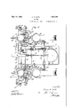
- Figure 1 is a plan view of the implement.
- Figure 2 is a side elevational view of the same.
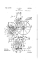
- Figure 3 is a fragmentary rear view illustrating the central furrow opener for opening t-he seed furrow, and the two laterally disposedy furrow openers for opening the fertilizer furrows.
- Figure 4 is a fragmentary sectional view taken on the plane of the line 4-4 of Figure 1 and illustrating this grouping ⁇ of the furrow openers
- Figure 5 is a horizontal sectional view taken on the vplan'e of the line 5 5 of Figure et.4
- Figure G is a view similar to Figurefl, illustrating a modified construction.
- Figure 7 Figure 8 t is a vertical sectional view through the front portion of the runner' vwhich opens the seed furrow.
- Figure 9 is a vertical sectional view showing the Loperation of depositing the fertilizer is a rear elevational View thereof.
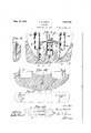
- Figure 10 is a fragmentary View, taken in the rear of Figure 9, and illustrating the next succeeding step of covering the seed furrow andthe fertilizer furrows by coveringblades.
- Figure 1 1 is a diagrammatic .view illustrating the approximate distribution of the fertilizer lwith respect to the seed when -both are deposited in th'eii1 respective furrows Yunder check-row operation;
- Figure 12 is a similar view showing the approximate distribution ofthe fertilizer with chain 32, which has suitable operative con- ⁇ respect to the seed when both are deposited in their furrows in a drilling operation. While the aforementioned object of depositing the fertilizer in separate furrows spaced laterally from the seed furrow has general application to various types of planters, the feature of also controlling the depositing of the fertilizer by check-row mechanism has particular application to planting implements designed either for check-row planting or for drilling, and accordingly l have disclosed my invention as embodied in such type of implement.
- Figures 1 and 2 illustrate a typical two-row planter of this type, the same being commonly referred to as a corn planter, although they are also extensively used for the planting of beans, peas, peanuts, etc.
- the implement comprises the usual back frame 15 and front frame 16, which are pivotally connected together at 17.
- Yfront frame comprises two spaced parallel bars 18-18 to which cross braces 19 are secured, the two frames being pivoted together at these cross bra-ces.
- Secured to the back frame 15 is the usual axle 21 on whichfthe two traction wheels 22 are journaled, the latter being usually arranged for shiftable adjustment inwardly and outwardly on the axle.
- the operators seat 23 is Supported on the back frame 15, being secured to front and rear pairs of supporting bars 24 and 25, the front pair of bars 24 being secured at their lower ends to a cross Abar 26,
- the usual tilting or adjusting lever 27 for raising and lowering the furrow openers is., shown as being pivoted to the front bars V24.
- each of said hoppers Associated with each of said hoppers is any conventional feeding mechanism foil causing a substantially uniform feed of the fertilizer from the hopper down into the boots which discharge the fertilizer into the lateral furrows.
- a revolving hopper bottom and a stirring arm may be employed, the mounting and operation of the same being ⁇ well known.
- the feeding mechanism of each hopper is indicated generally at 31, and is driven by a nection therewith.
- Each chain passes over an individual sprocket wheel 33 driven by the adjacent traction wheel 22, and any suitable clutchmechanism may be provided for manually starting and stopping the drive of the feed mechan'sm 31.
- Automatic means may also be provi ed for the purpose of interrupting the feed of fertilizer when. the furrow openers are raised clear of the ground, the
- links y34 which are operatively connected between the front frame 16 and the fertilizer feed mechanism, being representative of such automatic control means.
- the fertilizer is discharged from the feed mechanism 31 into a spout or tube 35 which conveys the same down into a divided duct or conduit 36.
- the two branches thereof 36--36 ⁇ (Fig. 3) distribute the fertilizer laterally to boot or val-ve members through which the fertilizer is deposited into thev lateral furrows, as I sha1] presently describe.
- two seed hoppers 37 Mounted on the front frame 16 are two seed hoppers 37, with which are associated suitable seed feeding or delivering mechanisms, represented by the rotatingseedplate 38 shown in Figure 4. These seed separating and feeding mechanisms may be of any preferred type, and require no detailed description since in and of themselves they constitute no part of the present invention.
- two delivering or feeding mechanisms 38 of both seed hoppers are driven by a cross shaft 39 which has bearing support on the front frame 16, and which is driven by a sprocket chain 40 extending back to the axle 21.
- the chain is adapted to pass selectively over any one of a series of sprockets 41 of different diameters, whereby the rate of travel of the chain can be adjusted.
- the drive of the chain 40 is transmitted to the shaft 39 through a variable speed unit indicated in its entirety at 42 ( Figure l), the latter being of any conventional type for securing a variable drop of the seed in order that different numbers of the seeds or kernels can be planted in each hill, as desired.
- Any suitable clutch mechanismy 43 may be provided for throwing the seed delivering mechanisms into and out of operation.
- each of these mechanisms comprising an oscillatory fork or lever 45 adapted to be engaged by the buttons or stop members on the check-wire.
- the guiding of the check-wire and the general construction of the check heads is old and well known, and need not be described in detail.
- Each fork or lever 45 i-s usually mounted on a rock shaft 46 which is pivotally supported on the front frame 16, and has operative connection with the clutch mechanism ⁇ 43 and also with suitable valve mechanism which controls the hill dropping of the seed.
- the two seed furrows may be opened by any suitable furrow openers, such as discs, runners or the like, but'in the preferred construction I employ furrow openers of the runner type, such as are indicated at 47.
- the upwardly curved front end of each runner is secured to the front frame by bracing links 48, and the rear,l end of the runner is secured to a runner shank 49 which is also bolted to the front frame between the side barsf18-.
- each runner shank is constructed in the form of a frame 49, on which is mountedthe seed hop er 37.
- the shaft 46 usually extends throng this open frame.
- the front partof each runner is formed with a relatively thin cutting edge (Figure 8), and from this front portion the runner tapers outwardly and rearwardly to form a seed trench or furrowof the desired width.
- the two side walls 51 shown in Figure 9 represent the separated side walls of the runner adjacent to the rear endthereof.
- the seed is delivered from each hopper 37, through the feeding mechanism 38, into a passage which extendsdown through the runner shank 49 and which discharges into the seed furrow between the side walls 51 51.
- the runner shank is controlled by .a suita le arrangement of the seeds delivered by the feeding mechanism the Vcheck-wire.
- These laterally disposed furrowopeners may be of the disc. type,.a ⁇ s shown in Figures 4 and bracket or yoke 63 extends transversely of ⁇ the runner shank with its central portion ⁇ arched over the runner 47, the bracket being secured'to the mountingblock 61 by a bolt 64. Extending forwardly and vdownwardly from the opposite sides of the bracket) 63 are bearing bosses 65, on which the discs 59 are rotatably supported. The discs are preferably set at an angle to throw the soil turned up out of the furrows b towards the outer sides of the furrows. The discs may be set to run at any desired furrowopening depth by Iloosening the U-bolt 62 and sliding theA block '61. and bracket 63 upwardlyor downrvardlyv along the runner shank 49.
- each of such valve members is in the form of a receptacle open at top and bottom and having its open lower end normally disposed above a plate member 67 extending rearwardly from the lowerpart of the yoke shaped bracket 63.
- the boot or receptacle memberl 66 and the closure member 67 constitute the two elements of a dumping valve which controls the depositing ofthe fertilizer, the closure member 67 being stationary and normallyu closing the lower end of the receptacle member, and the latter being mounted for swinging movement into and out' of cooperative registry with the closure member.
- Ieach arm of the yoke shaped bracket 63 is bifurcated at its rear end to form the two spaced arms 68.
- Each valve member 66 is provided with laterally spaced pivot ears 69 which project upwardly therefrom and engage. over the outer sides of the arms 68.
- a pivot pin 71 passes through the arms and pivot ears, and pivotally supportsthe valve member for fore and aft s'win'gin movement.
- Al lug or ear 72 also projects orwardly from each branch 36 of the branch conduit and extends between the arms 68, where the pivot pin 71 passes through suchl lug or conduit in communication with the upper end of the vvalve member 66.
- the branch conduit branch conduit 36 accumulates on the closure 'ing forwardly from the inner pivot" ⁇ ear 69 is an arm 7 3 which has a pivotal connection at its outer end with a link 74.
- the upper portion of such link comprises a sleeve 75 which is forked to'engage over the crank pin 54 which.
- the forked portion 76 vof the sleeve has readily attachable and detachable connection/with the crank pin, as by the Aprovision of a cotter pin or the like extending between thearms of the forkon the front side of the crank pin.
- the sleeve 75 is internally threaded for receiving the vthreaded upperend ofthe lower portion of the link 74 whereby the effective length of the' link can be adjusted for'controlling the nor- -mal position and ⁇ range of movementof .the .boot ⁇ 66. lSuch a'djustability of the length of the link also accommodates the different depth settings of the discs along the runner shank 49;
- the fertilizer which is fed down through the member 67 between successive actuations of the valve member 66.
- the shaft 46 is loscillated, causing operation of the upper and lower seed valves to drop the hill of seeds into the center furrow.
- valve 41rne1nber466 is swung rearwardly off of the end of the closure 4member 67,-
- the valve member 66 is also re-n turned'to-its j normal position for receiving another accumulation of fertilizerpreparatory to the next succeeding operation of the check-row mechanism.l AWhen, the implement is to be used for drilling, the seed valves are locked in their open positions, and at such time the botmember 66 is correspondingly held in its open position, i. e.,”swung rearwardly with its lower end out of registry with the plate member 67, so that the fertilizer is deposited continuously through the boot member.
- the seed valves may be made to operate for securing a check-row planting of the seed whilethe fertilizer vvalve member 67 is held continuously open for depositing the fertilizer continuously in the fertilizer furrows b.
- the forked upper end 76 of the link 74 may be engaged over a pin 77 projecting laterally from the runner shank.
- each of the lateral furrow openers 59 in such construction consists of runners made up of two plates l78--7 8.
- the curved Aforward edges of such plates are'se'cured together to form a relatively sharp edge for cutting the soil, and the rear portions of the plates are separated from each other to-form afertilizer-receiving furrow of the desired width.
- Each of .such lateral furrow openers is secured to Va .standard -orsupporti'ng arm 79 which supports the furrow opener on the front frame 16.
- the lower endof the arm 79 extends between the spaced plates 78 andy is rigidly secured'thereto by abolt .81.
- the upper end of the supporting arm 7 93 is adjustablyclamped to the front of the frame bar 18 by a U-shaped clamping bolt r82 which embraces the supporting arm and frame bar.
- a U-shaped clamping bolt r82 which embraces the supporting arm and frame bar.
- each furrow opener is a block 83 from which'extends a curved arm or plate member 84', The latterconstitutes a closure member for a swinging valve85, similarly tothe valve construction in the preceding embodiment.
- the vvalve .member 8 5 consists of a ring or 4lll receptacle serving as a movable lower end for the branch extension'36 oftheconduit 36.
- each branch eX- tension 36 is preferably constructed in the form o f a spiraled metal conduit which -can swing fore and aft with the swinging movement of the valve member 85, and which can 'lll also expand or contract with a telescopic movement, for accommodating different depth adjustments ofthe fertilizer runners 59.
- Each valve member 85 has a lug 87 ( Figure 7 projecting upwardly therefrom,
- each of. the embodiments shown in Fig' ures 4 and 6 the operation of covering the three furrows a and b-b after the deposltin of the seed and fertilizer therein, is performed by a pair of covering bladesv 94.
- the rear ends of these blades are curved inwardly to scrape or deect the ridges of soil which have been turned up along the sides of the three furrows'back into said furrows in a covering operation.
- ⁇ it will lbe noted that the front portion of each blade extends up.- wardly between the bars 18 '18 of the front frame, where the blade has pivotal connection at 95 to ay bracket 96 secured tothe rear frame bar 18.
- each blade above the pivot 95 has pivotal attachment at 97 to a bolt 98 whichextends rearwardly through an opening in a stationary arm 96( extending up from' the bracket 96.
- A. compression spring 99 is confined on vthis bolt between the' arm 96 and a nut 100 screwing over the rear end of the bolt. It will be observed that the pressure of the spring 99 is .normally effective to force the lower end of the blade down into yielding engagement with the soil, whereby the blade is heldin effective engagement with the soil for deflect- 4ing the same into the furrows, but is per-- mitted to swing upwardly upon striking clods or stones in the soll.'
- 55-57 is setfor check-row operation or is held in open position, the seeds c will be planted in hills or will be planted singly.
- the fertilizer will be deposited from'the fertilizenfeeding apparatus representedl by the hopper 29, feeding mechanism 81 and conduitA means 35--36 .v
- the fertilizer will be deposited intermittently intsaid furrows with the check-row planting of the seed, or will be deposited continuously withrthe drilling of the seed, depending upon whether the fertilizer valve means ,66-85 is operatively connected for intermittent movement with ythe seed valve Ymechanism 55-57, or is held continuously in its open position.
- the covering blades 94 in following along behind the three furrow openers, scrape the adjacent soil, including the rid es turned Vup along the sides of the furrows, ack into the three furrows to cover .the seeds and to cover the deposits of fertilizer, as shown in Figure 10.
- Figure 11 illustrates Iapproximately the distribution of the fertilizer withrespectto the seed when :both are deposited in their respective furrows under check-row operation. It will b e observed that each deposit of fertilizer is located substantially directly opposite its individual hill of seeds, so that the fertilizer will be in close proximity to the seeds for transferring its nutritive properties thereto.
- Figure 12 illustrates the distril bution of the fertilizer with respect to the tion wheels 22 also assist in this covering op- .seed when both arel deposited in their respective furrows in a drilling operation, i. e.,
- the fertilizer is irnbedded in the soil in the form ofaccumulated or concentrated deposits d. Preferably these l deposits arebelow the planted depth of the seed, although the fertilizer may, of course,
- tlielateral furrow openers 59 can be shifted towards and away from the'seed furrow opener for securing a different spacing of the fertilizer Y, .deposits V with respect to the seed such adjustment of the lateral furrow openers being accomplished by loosening the U shaped clainpingfbolts 82 and shifting the supporting arms 79 laterally along the frame bar-18.
- an intermediate furrow openerl for opening a-seed furrow, said intermediate furrow opener-having an upwardly extending shank, seed lfeeding means discharging into said furrow, laterally disposed furrow'openers adjustably mountedon said shank for opening secondary furrows on each'sidewfsaid seed furrow, fer-- tilizer feeding means discharging into said l secondary furrows, and check-row mechanism cooperating with each of said feeding means for controlling lthe feed of,seed and fertilizer. into said furrows.
- a runner for opening a seed furrow a, runner shank supporting said runner, means for planting-seed in said seed furrow, a pair of furrow opening discs' dis- -posed laterally of said runner and adapted to open Asecondary furrows 'spaced laterally from said seed-furrow, means for detachably securing said dis'csto said runner shank, and means for depositingfertilizerin said secondary'furi'ows.
- -seed valve mechanism adapted to control planting of the seed, lateral furrow openers adapted toopen secondary furrows on each 'sidefof said seed furrow, a fertilizer hopper,
- 'conduit means lextending down from' said hopper and-adapted to depositfertilizer in l each of said secondary furrows at points approximately in -the saine transverse plane with the seed in said seed furrow, relatively stationary closure'meinbers agapted to close loci ⁇ the discharge ends of said con uit means, and
- a combined planterand fertilizer distributar the combination of a" runner for opening a seed furrow, a runner shank supporting ⁇ said runner, means for planting seedv therefrom for discharging fertilizer directly in rear of said discs into said secondary furrows, stationary closure members carried bysaid bracket and adapted to close the branched ends of said conduit, and means for moving the latter ends of said conduit out of operative registry with said closure members.
- a seed furrow opener having a shank portion extending upwardly therefrom, means for planting seed in the furrow opened thereby, a secondary furrow opener for opening a fertilizer furrow spaced laterally from said seed furrow, means for depositing fertilizer in said fertilizer furrow, and means adjustably supporting said secondary furrow opener on said shank portion of the seed furrow opener, said means comprising a mounting block secured to said secondary furrow opener, and a U-bolt connected to said mounting block and embracing the shank-portion of said seed furrow opener.
- the combinationof a runner adapted to open a seed furrow, said runner having-an upwardly extending shank, means for planting seed in said seed furrow, secondary furrow openers adapted to open secondary furrows spaced laterally from said seed furrow, means for depositing fertilizer in each of said secondary furrows, and means adjustably supporting said secondary furrow openers on said upwardly extending shank for permit- ⁇ ting different depth adjustments thereof, said means comprising a transversely extending yoke secured to said secondary furrow openers, and a U-shaped bolt connectedwith said yoke and embracing said upwardly eX- tcnding shank.
Landscapes
- Life Sciences & Earth Sciences (AREA)
- Soil Sciences (AREA)
- Environmental Sciences (AREA)
- Transplanting Machines (AREA)
- Fertilizing (AREA)
- Sowing (AREA)
Description
,May 10, 1932 c. H. WHITE 1,857,749'
PLANTER Filed July 18, 1927 5 sheets-sheet '2 Wwf W r @f LM- -f .Wem
May 10, 1932. c. H. WHITE 1,857,749
PLANTER Filed' July 18, l927 5 Sheets-Sheet 3 May l0, 1932. Q H. WH|TE 1,857,749
` PLANTER Filed Ju1y.l8. 1927 5 Sheets-Sheet 4 Patented May 10, 1932 PATENT oFFlc' CHARLES H. WHITE, OF MOLINE, ILLINOIS, ASSIGNOR TO DEERE & COMPANY, OF
. MOLINE, ILLINOIS, A CORPORATION OF ILLINOIS PLANTER Application filed July 18,-
The present invention relates to planting implements of the type whiclrdistribute fer.- tilizer along with the planting operation, as by depositing the fertilizer in a furrow or furdrows in the seed bed in proximity to the see In distributing fertilizer in this manner it is desirable that the fertilizer be imbedded in the soil in close proximity to the seed so that the seed and the growing plant will derive the full benefit of the nourishing properties of the fertilizer, but at the same time no appreciable quant-ity of the fertilizer should be allowed to come into direct contact with the .y
seed, as such has a tendency to detrimentally affect the germination of the seed and the growth of the plant. rlhe latter is commonly referred to as firing of the seed and should be avoided in practically all planting operations.
The principal object of the invention is to provide an improved method of planting seed and distributing fertilizer by which the fertilizer is deposited in the seed bed in such proximity to the seed, and to the plant and roots sprouting therefrom, that the seed and plant will derive the full benefit of lthe fertilizer, but without the possibility of the seed being fired by the fertilizer. More specifically, this distribution consists in depositing the fertilizer inn two separate furrows which'are opened on each side of the seed furrow, so that quantities of `the fertilizer are'distributed laterally to each side of the seed.
A further object of the invention is to 'provide improved apparatus for carrying out this method, and characterized principally by an improved arrangement of furrow openers for forming the two fertilizer furrows on, oppositesides of the seed furrow.
Another object of the invention is to pro- -vide an improved construction of valve mechanism whichv has cooperative association with the4 fertilizer distributin means for controlling the depositing of t e fertilizer. Such valve mechanism is adapted to be operatively connected with the check-row valve mechanism of the planter so that the fertilizer can be deposited in hills/along with 1927. 'Serial N0. 206,428.
` thereof.
In the drawings illustrating such embodiment:
Figure 1 is a plan view of the implement.
Figure 2 is a side elevational view of the same.
Figure 3 is a fragmentary rear view illustrating the central furrow opener for opening t-he seed furrow, and the two laterally disposedy furrow openers for opening the fertilizer furrows. i
Figure 4 is a fragmentary sectional view taken on the plane of the line 4-4 of Figure 1 and illustrating this grouping` of the furrow openers,
Figure 5 is a horizontal sectional view taken on the vplan'e of the line 5 5 of Figure et.4
Figure G is a view similar to Figurefl, illustrating a modified construction.
Figure 7 Figure 8 t, is a vertical sectional view through the front portion of the runner' vwhich opens the seed furrow.
l Figure 9 is a vertical sectional view showing the Loperation of depositing the fertilizer is a rear elevational View thereof.
in the two furrows 0r trenches formed laterally of the seed furrow.
Figure 10 is a fragmentary View, taken in the rear of Figure 9, and illustrating the next succeeding step of covering the seed furrow andthe fertilizer furrows by coveringblades.. Figure 1 1 is a diagrammatic .view illustrating the approximate distribution of the fertilizer lwith respect to the seed when -both are deposited in th'eii1 respective furrows Yunder check-row operation; and
Figure 12 is a similar view showing the approximate distribution ofthe fertilizer with chain 32, which has suitable operative con-` respect to the seed when both are deposited in their furrows in a drilling operation. While the aforementioned object of depositing the fertilizer in separate furrows spaced laterally from the seed furrow has general application to various types of planters, the feature of also controlling the depositing of the fertilizer by check-row mechanism has particular application to planting implements designed either for check-row planting or for drilling, and accordingly l have disclosed my invention as embodied in such type of implement. Figures 1 and 2 illustrate a typical two-row planter of this type, the same being commonly referred to as a corn planter, although they are also extensively used for the planting of beans, peas, peanuts, etc. ln describing the implement l shall only make brief reference to those elements which are old and well known. The implement comprises the usual back frame 15 and front frame 16, which are pivotally connected together at 17. rlhe Yfront frame comprises two spaced parallel bars 18-18 to which cross braces 19 are secured, the two frames being pivoted together at these cross bra-ces. Secured to the back frame 15 is the usual axle 21 on whichfthe two traction wheels 22 are journaled, the latter being usually arranged for shiftable adjustment inwardly and outwardly on the axle. The operators seat 23 is Supported on the back frame 15, being secured to front and rear pairs of supporting bars 24 and 25, the front pair of bars 24 being secured at their lower ends to a cross Abar 26,
which reinforces the back frame. The usual tilting or adjusting lever 27 for raising and lowering the furrow openers is., shown as being pivoted to the front bars V24.
Rising from the sides of the back frame are two brackets l28 which support the two fertilizer hoppers 29, each of these hoppers supplying fertilizer to one of the planting rows. Associated with each of said hoppers is any conventional feeding mechanism foil causing a substantially uniform feed of the fertilizer from the hopper down into the boots which discharge the fertilizer into the lateral furrows. As exemplary of such feeding mechanism, a revolving hopper bottom and a stirring arm may be employed, the mounting and operation of the same being `well known. The feeding mechanism of each hopper is indicated generally at 31, and is driven by a nection therewith. Each chain passes over an individual sprocket wheel 33 driven by the adjacent traction wheel 22, and any suitable clutchmechanism may be provided for manually starting and stopping the drive of the feed mechan'sm 31. Automatic means may also be provi ed for the purpose of interrupting the feed of fertilizer when. the furrow openers are raised clear of the ground, the
links y34, which are operatively connected between the front frame 16 and the fertilizer feed mechanism, being representative of such automatic control means. The fertilizer is discharged from the feed mechanism 31 into a spout or tube 35 which conveys the same down into a divided duct or conduit 36. The two branches thereof 36--36` (Fig. 3) distribute the fertilizer laterally to boot or val-ve members through which the fertilizer is deposited into thev lateral furrows, as I sha1] presently describe.
Mounted on the front frame 16 are two seed hoppers 37, with which are associated suitable seed feeding or delivering mechanisms, represented by the rotatingseedplate 38 shown in Figure 4. These seed separating and feeding mechanisms may be of any preferred type, and require no detailed description since in and of themselves they constitute no part of the present invention. rlhe two delivering or feeding mechanisms 38 of both seed hoppers are driven by a cross shaft 39 which has bearing support on the front frame 16, and which is driven by a sprocket chain 40 extending back to the axle 21. Here the chain is adapted to pass selectively over any one of a series of sprockets 41 of different diameters, whereby the rate of travel of the chain can be adjusted. The drive of the chain 40 is transmitted to the shaft 39 through a variable speed unit indicated in its entirety at 42 (Figure l), the latter being of any conventional type for securing a variable drop of the seed in order that different numbers of the seeds or kernels can be planted in each hill, as desired. Any suitable clutch mechanismy 43 may be provided for throwing the seed delivering mechanisms into and out of operation.
Also mounted on the front frame 16 at the outer ends thereof are conventional checkrow mechanisms indicated generally at 44, each of these mechanisms comprising an oscillatory fork or lever 45 adapted to be engaged by the buttons or stop members on the check-wire. The guiding of the check-wire and the general construction of the check heads is old and well known, and need not be described in detail. Each fork or lever 45 i-s usually mounted on a rock shaft 46 which is pivotally supported on the front frame 16, and has operative connection with the clutch mechanism` 43 and also with suitable valve mechanism which controls the hill dropping of the seed. f
The two seed furrows may be opened by any suitable furrow openers, such as discs, runners or the like, but'in the preferred construction I employ furrow openers of the runner type, such as are indicated at 47. The upwardly curved front end of each runner is secured to the front frame by bracing links 48, and the rear,l end of the runner is secured to a runner shank 49 which is also bolted to the front frame between the side barsf18-.
18. The upper portion of each runner shank is constructed in the form of a frame 49, on which is mountedthe seed hop er 37. The shaft 46 usually extends throng this open frame. The front partof each runner is formed with a relatively thin cutting edge (Figure 8), and from this front portion the runner tapers outwardly and rearwardly to form a seed trench or furrowof the desired width. The two side walls 51 shown in Figure 9 represent the separated side walls of the runner adjacent to the rear endthereof. The seed is delivered from each hopper 37, through the feeding mechanism 38, into a passage which extendsdown through the runner shank 49 and which discharges into the seed furrow between the side walls 51 51. In check-row planting lthe dropping of the seeds or kernels throu h the runner shank is controlled by .a suita le arrangement of the seeds delivered by the feeding mechanism the Vcheck-wire.
38 so that an accumulation of two, three or four seeds is dropped into the furrow in a hill with each actuation of the lever 45 by The rock shaft 46 toward each of its ends has crank arms 53-mounted thereon, between each pair of which extends a crank pin 54.l The latter engages in a slotted yoke 55 extending from the upper valve unit, and the motion of this valve unit is transmitted tothe lower valve unit through a link or rod 56. The lower valve 4unit is indicated at 57 in Figure 9, the same being pivoted in the lower end ofthe runner on the vtransversepin 58. A foot lever or any other suitable control member is usually provided for the purpose of holdingthe upper and lower valves in their open positions,at which time the dropping of the seeds or kernels into the furrow is controlled entirely by the feeding mechanism 38, corresponding to the drilling of the seed.
I shall only describe -the lateral furrow openers and the fertilizer dump. valve mechanism in connection with one of the runners 47, as this same mechanism is duplicated at. the other runner. I shall also describe the fertilizer distributing apparatus in its preferred form of an attachmentadapted for ready mounting on or dismounting from the implement, but it will be obvious that the fertilizer distributing mechanism can be. constructed -in its entirety as a unitar part of the implement. Mounted on each side of the runner 47 are furrow openers 59 which cut 'two fertilizer furrows or trenches b on each side of the seed furrow a (see Figure 9).`
These laterally disposed furrowopeners may be of the disc. type,.a`s shown in Figures 4 and bracket or yoke 63 extends transversely of` the runner shank with its central portion `arched over the runner 47, the bracket being secured'to the mountingblock 61 by a bolt 64. Extending forwardly and vdownwardly from the opposite sides of the bracket) 63 are bearing bosses 65, on which the discs 59 are rotatably supported. The discs are preferably set at an angle to throw the soil turned up out of the furrows b towards the outer sides of the furrows. The discs may be set to run at any desired furrowopening depth by Iloosening the U-bolt 62 and sliding theA block '61. and bracket 63 upwardlyor downrvardlyv along the runner shank 49.
The fertilizer is conveyed down through the. laterally diverging branches 36 of the divided conduit 36 and is thence discharged into boots or valve members 66 which are disposed on-the inner sides of the discs, approximately above the bottomsof the furrows b. Referring to Figure l4, each of such valve members is in the form of a receptacle open at top and bottom and having its open lower end normally disposed above a plate member 67 extending rearwardly from the lowerpart of the yoke shaped bracket 63. The boot or receptacle memberl 66 and the closure member 67 constitute the two elements of a dumping valve which controls the depositing ofthe fertilizer, the closure member 67 being stationary and normallyu closing the lower end of the receptacle member, and the latter being mounted for swinging movement into and out' of cooperative registry with the closure member. Referring to Figure 5, it will be noted that Ieach arm of the yoke shaped bracket 63 is bifurcated at its rear end to form the two spaced arms 68. Each valve member 66 is provided with laterally spaced pivot ears 69 which project upwardly therefrom and engage. over the outer sides of the arms 68. A pivot pin 71 passes through the arms and pivot ears, and pivotally supportsthe valve member for fore and aft s'win'gin movement. Al lug or ear 72 also projects orwardly from each branch 36 of the branch conduit and extends between the arms 68, where the pivot pin 71 passes through suchl lug or conduit in communication with the upper end of the vvalve member 66. The branch conduit branch conduit 36 accumulates on the closure 'ing forwardly from the inner pivot"` ear 69 is an arm 7 3 which has a pivotal connection at its outer end with a link 74. The upper portion of such link comprises a sleeve 75 which is forked to'engage over the crank pin 54 which. actuates the seed valves, or over a separate crank pin also having crank arm mounting on the shaft 46. The forked portion 76 vof the sleeve has readily attachable and detachable connection/with the crank pin, as by the Aprovision of a cotter pin or the like extending between thearms of the forkon the front side of the crank pin. The sleeve 75 is internally threaded for receiving the vthreaded upperend ofthe lower portion of the link 74 whereby the effective length of the' link can be adjusted for'controlling the nor- -mal position and`range of movementof .the .boot`66. lSuch a'djustability of the length of the link also accommodates the different depth settings of the discs along the runner shank 49;
In the operation of such embodiment, the fertilizer which is fed down through the member 67 between successive actuations of the valve member 66. When a button or stop on the check-wire strikes the check-row 'forkV 45 the shaft 46 is loscillated, causing operation of the upper and lower seed valves to drop the hill of seeds into the center furrow.
Simultaneously with the actuation of ,such seed valves the-link 74 is Athrust downwardly,
`and the valve 41rne1nber466 is swung rearwardly off of the end of the closure 4member 67,-
thus -wiping the accumulation of fertilizer -oif of the closure member'and vdropping the same-from the end of the valve boot downv into the fertilizer furrow b directly in rear.v
' of the adjacent disc 59. With the restoration of the seed valves to normalposition, such lbeing usually performed by suitable spring mechanism, the valve member 66 is also re-n turned'to-its j normal position for receiving another accumulation of fertilizerpreparatory to the next succeeding operation of the check-row mechanism.l AWhen, the implement is to be used for drilling, the seed valves are locked in their open positions, and at such time the botmember 66 is correspondingly held in its open position, i. e.,"swung rearwardly with its lower end out of registry with the plate member 67, so that the fertilizer is deposited continuously through the boot member. It Willbe understood that by disconnecting `the upper end of the link 74 from the crank pin 54, or by disconnecting the lower end of such link from the arm 7 3, the seed valves may be made to operate for securing a check-row planting of the seed whilethe fertilizer vvalve member 67 is held continuously open for depositing the fertilizer continuously in the fertilizer furrows b. For holding the boot member 66 in its open position at such time, the forked upper end 76 of the link 74 may be engaged over a pin 77 projecting laterally from the runner shank.
Referring now to Athe modified construction shown in Figures 6 and 7, each of the lateral furrow openers 59 in such construction consists of runners made up of two plates l78--7 8. The curved Aforward edges of such plates are'se'cured together to form a relatively sharp edge for cutting the soil, and the rear portions of the plates are separated from each other to-form afertilizer-receiving furrow of the desired width. Each of .such lateral furrow openers is secured to Va .standard -orsupporti'ng arm 79 which supports the furrow opener on the front frame 16. The lower endof the arm 79 extends between the spaced plates 78 andy is rigidly secured'thereto by abolt .81. The upper end of the supporting arm 7 93 is adjustablyclamped to the front of the frame bar 18 by a U-shaped clamping bolt r82 which embraces the supporting arm and frame bar. Such mounting of the supporting arm'permits the vertical adjustment of the furrow opener 59 for obtaining any 4desired depth of the fertilizer furrow b.
Rigidlyn secured between the side plates 78 .of each furrow opener is a block 83 from which'extends a curved arm or plate member 84', The latterconstitutes a closure member for a swinging valve85, similarly tothe valve construction in the preceding embodiment. The vvalve .member 8 5 consists of a ring or 4lll receptacle serving as a movable lower end for the branch extension'36 oftheconduit 36. In the present embodiment -each branch eX- tension 36 is preferably constructed in the form o f a spiraled metal conduit which -can swing fore and aft with the swinging movement of the valve member 85, and which can 'lll also expand or contract with a telescopic movement, for accommodating different depth adjustments ofthe fertilizer runners 59. Each valve member 85 has a lug 87 (Figure 7 projecting upwardly therefrom,
and to this lug is rigidly bolted the .lower arm of a bell crank lever 88. oted at 89 to' a supporting arm 91 which extends upwardly from'therunner 59. The
forwardly extending arm of the lever has 'ag longitudinal slot 92 therein, in which is Suchlever is pivclamped a pivot bolt 9 3. The pivot bolt is l shiftable to any desired" position along the link 74 which is substantially similar to the` link 74 `previously described. The upper end of such link has operative connection with the crank pin 54, or with any individual crank pin carried by the rock'shaft 46, as
' previously described.
The operation of this embodiment is generally similar to the operation of theembodiment shown in Figures 4 and 5. The runners 59" open secondary furrows b spaced lat erally from the seed furrow a. When the fertilizer'is to be deposited intermittently along with the v,check-row planting of the seed, the valve member 85 'is oscillated out of registry with the closure member 84 with each actuar tion of the seed valve mechanism, thus drope pingthe collected quantity of fertilizer in the branch conduit 36 down into the lateral furrow b. This operation, of course, applies t0.
In each of. the embodiments shown in Fig' ures 4 and 6, the operation of covering the three furrows a and b-b after the deposltin of the seed and fertilizer therein, is performed by a pair of covering bladesv 94. As shown in Figures 5 and 10, the rear ends of these blades are curved inwardly to scrape or deect the ridges of soil which have been turned up along the sides of the three furrows'back into said furrows in a covering operation. Referring to Figure 4, `it will lbe noted that the front portion of each blade extends up.- wardly between the bars 18 '18 of the front frame, where the blade has pivotal connection at 95 to ay bracket 96 secured tothe rear frame bar 18. `The upper end of each blade above the pivot 95 has pivotal attachment at 97 to a bolt 98 whichextends rearwardly through an opening in a stationary arm 96( extending up from' the bracket 96. A. compression spring 99 is confined on vthis bolt between the' arm 96 and a nut 100 screwing over the rear end of the bolt. It will be observed that the pressure of the spring 99 is .normally effective to force the lower end of the blade down into yielding engagement with the soil, whereby the blade is heldin effective engagement with the soil for deflect- 4ing the same into the furrows, but is per-- mitted to swing upwardly upon striking clods or stones in the soll.'
It will alsd be un-- In the operation of the implement the inling upon whether the seed valve mechanism.
55-57 is setfor check-row operation or is held in open position, the seeds c will be planted in hills or will be planted singly.
-Concurrently with the opening of the seed furrow al the two lateral furrow openers 59--59 will also o en the secondary or fertilizer furrowsgb. nto such secondary fur- .rows the fertilizer will be deposited from'the fertilizenfeeding apparatus representedl by the hopper 29, feeding mechanism 81 and conduitA means 35--36 .v The fertilizer will be deposited intermittently intsaid furrows with the check-row planting of the seed, or will be deposited continuously withrthe drilling of the seed, depending upon whether the fertilizer valve means ,66-85 is operatively connected for intermittent movement with ythe seed valve Ymechanism 55-57, or is held continuously in its open position. The covering blades 94 in following along behind the three furrow openers, scrape the adjacent soil, including the rid es turned Vup along the sides of the furrows, ack into the three furrows to cover .the seeds and to cover the deposits of fertilizer, as shown in Figure 10. The trac'- eration. l t
Figure 11 illustrates Iapproximately the distribution of the fertilizer withrespectto the seed when :both are deposited in their respective furrows under check-row operation. It will b e observed that each deposit of fertilizer is located substantially directly opposite its individual hill of seeds, so that the fertilizer will be in close proximity to the seeds for transferring its nutritive properties thereto. Figure 12 illustrates the distril bution of the fertilizer with respect to the tion wheels 22 also assist in this covering op- .seed when both arel deposited in their respective furrows in a drilling operation, i. e.,
when the seed valve mechanism 55-57-and the fertilizer valve means 66-.85 are held in their open inoperative positions. By disto deposite the fertilizer as two continuous bands on opposite sides-of the seed row, as
shown in Figure 12. It will be noted that the fertilizer is irnbedded in the soil in the form ofaccumulated or concentrated deposits d. Preferably these l deposits arebelow the planted depth of the seed, although the fertilizer may, of course,
be deposited at any desired level above or below tlc e seed, as desired by giving the lateral furrow openers the proper depth adjustment.
By imbedding the deposits fertilizer d below the seed the roots sprouting therefrom reach the fertilizer deposits and absorb the nutri-.fupwardly extending shank for A permittingl tive properties thereof. In the construction shown in Figures 6 and 7 tlielateral furrow openers 59 can be shifted towards and away from the'seed furrow opener for securing a different spacing of the fertilizer Y, .deposits V with respect to the seed such adjustment of the lateral furrow openers being accomplished by loosening the U shaped clainpingfbolts 82 and shifting the supporting arms 79 laterally along the frame bar-18. f
What I claim as my invention and desire to secure by Letters Patent is 1. In a combined' planter and fertilizer distributor, the combination of an intermediate furrow opener for opening a seed furrow, said intermediate furrow opener having an upwardly extending shank, seed feeding means discharging into said furrow, laterall ly disposed furrowppeners mounted on said shank for opening secondary furrow on each side of s'aidseed furrow, fertilizer feeding means discharging into said secondary furrows, and coacting valve means cooperating with each of said feeding means for controlling the' feed of seed and fertilizer into. said furrows. i 2. In a combined planter and fertilizer distributor, the combination of an intermediate furrow openerl for opening a-seed furrow, said intermediate furrow opener-having an upwardly extending shank, seed lfeeding means discharging into said furrow, laterally disposed furrow'openers adjustably mountedon said shank for opening secondary furrows on each'sidewfsaid seed furrow, fer-- tilizer feeding means discharging into said l secondary furrows, and check-row mechanism cooperating with each of said feeding means for controlling lthe feed of,seed and fertilizer. into said furrows.
3. In an implement ofthe class described, the combination of a seed furrow'opener having a shank portion extending upwardly therefrom, means for planting seed in the furrow opened thereby, -a secondary furrow v opener disposed substantially in the same positing fertilizer in said fertilizer furrow,
transverse plane as said seed furrow opener for opening a fertilizer furrow spacedlaterallyA from said seed furrow,` means for deand means adjustably supporting said secon'dary furrow opener on said shank portion the combination of a runner adapted to open of the seed furrow openerfor different depth adju ments. l
4. an implement lof the class described,
a seed furrow, said runner having an upward.-
ly'extending shank, means for planting seed in said seed furrow, secondary furrow openers adapted to open secondary furrows spaced laterally from said/seed furrow, means for depositing fertilizer in each of said secondvondarv the discharge of fertilizer` from said conduit,
bly mounted on said seed furrow opener and adapted to open secondary'furrows on each side of the seed furrow, and means for depositing fertilizer in each of said secondary furrows. p Y,
6.. In an -implement of the class described, the combination of a runner for opening a seed furrow, a, runner shank supporting said runner, means for planting-seed in said seed furrow, a pair of furrow opening discs' dis- -posed laterally of said runner and adapted to open Asecondary furrows 'spaced laterally from said seed-furrow, means for detachably securing said dis'csto said runner shank, and means for depositingfertilizerin said secondary'furi'ows.
7. In an implement of the class described, the combination of an intermediate furrow means for planting the seed in said furrow,
-seed valve mechanism adapted to control planting of the seed, lateral furrow openers adapted toopen secondary furrows on each 'sidefof said seed furrow, a fertilizer hopper,
'conduit means lextending down from' said hopper and-adapted to depositfertilizer in l each of said secondary furrows at points approximately in -the saine transverse plane with the seed in said seed furrow, relatively stationary closure'meinbers agapted to close loci` the discharge ends of said con uit means, and
means actuated by said seed valve mechanism for )moving the discharge ends of said conduit means out of registry with said closure members.l`4 i 8.- In a combined planter and fertilizer distributor, the combination of a, seed furrow opener, means for planting seed in the furrow opened thereby, a disc for opening a secondar'vfurrow to one side of the seed furrow, a fertilizer hopper, -a conduit forvdischarging the fertilizer therefrom to said secfurrow, valve meansfor controlling anda bracket member on which' said disc is iournaled and said valve means is supported,
,said bracket being mounted on said seed .fur-
row opener.
9. In a combined planterand fertilizer distributar. the combination of a" runner for opening a seed furrow, a runner shank supporting` said runner, means for planting seedv therefrom for discharging fertilizer directly in rear of said discs into said secondary furrows, stationary closure members carried bysaid bracket and adapted to close the branched ends of said conduit, and means for moving the latter ends of said conduit out of operative registry with said closure members.
10. In an implement of the class described, the combination of a seed furrow opener having a shank portion extending upwardly therefrom, means for planting seed in the furrow opened thereby, a secondary furrow opener for opening a fertilizer furrow spaced laterally from said seed furrow, means for depositing fertilizer in said fertilizer furrow, and means adjustably supporting said secondary furrow opener on said shank portion of the seed furrow opener, said means comprising a mounting block secured to said secondary furrow opener, and a U-bolt connected to said mounting block and embracing the shank-portion of said seed furrow opener. 11. In an implement of the class described, the combinationof a runner adapted to open a seed furrow, said runner having-an upwardly extending shank, means for planting seed in said seed furrow, secondary furrow openers adapted to open secondary furrows spaced laterally from said seed furrow, means for depositing fertilizer in each of said secondary furrows, and means adjustably supporting said secondary furrow openers on said upwardly extending shank for permit-` ting different depth adjustments thereof, said means comprising a transversely extending yoke secured to said secondary furrow openers, and a U-shaped bolt connectedwith said yoke and embracing said upwardly eX- tcnding shank.
VCHARLES I-I. WHITE.
Priority Applications (1)
| Application Number | Priority Date | Filing Date | Title |
|---|---|---|---|
| US206428A US1857749A (en) | 1927-07-18 | 1927-07-18 | Planter |
Applications Claiming Priority (1)
| Application Number | Priority Date | Filing Date | Title |
|---|---|---|---|
| US206428A US1857749A (en) | 1927-07-18 | 1927-07-18 | Planter |
Publications (1)
| Publication Number | Publication Date |
|---|---|
| US1857749A true US1857749A (en) | 1932-05-10 |
Family
ID=22766331
Family Applications (1)
| Application Number | Title | Priority Date | Filing Date |
|---|---|---|---|
| US206428A Expired - Lifetime US1857749A (en) | 1927-07-18 | 1927-07-18 | Planter |
Country Status (1)
| Country | Link |
|---|---|
| US (1) | US1857749A (en) |
Cited By (14)
| Publication number | Priority date | Publication date | Assignee | Title |
|---|---|---|---|---|
| US2611331A (en) * | 1946-04-03 | 1952-09-23 | Int Harvester Co | Planter |
| US2749856A (en) * | 1952-10-08 | 1956-06-12 | Fleming Joseph | Fertilizer distributing apparatus for check-row corn planters |
| US3362361A (en) * | 1964-09-28 | 1968-01-09 | Massey Ferguson Inc | Planting method and apparatus |
| US3664279A (en) * | 1970-03-04 | 1972-05-23 | Rex Belden | Earth working and planting apparatus and method of planting seed |
| WO1985001417A1 (en) * | 1983-10-06 | 1985-04-11 | Wolf-Geräte Gmbh | Machine for ploughing furrows with parallel walls into grassland and lawns |
| US4653412A (en) * | 1985-11-01 | 1987-03-31 | Clarke George P | Deep band fertilizer and double side band seeding attachment |
| US4762075A (en) * | 1984-06-19 | 1988-08-09 | Halford James W | Seed/fertilizer minimum tillage planter |
| US5140917A (en) * | 1990-06-28 | 1992-08-25 | Swanson Guy J | Method and apparatus for seeding agricultural crops |
| US5413056A (en) * | 1994-01-19 | 1995-05-09 | Agricommunication And Technology, Inc. | Method and apparatus for no-till planting |
| US5660126A (en) * | 1994-01-19 | 1997-08-26 | Agricommunication And Technology, Inc. | Method and apparatus for no-till planting |
| US6029591A (en) * | 1998-09-03 | 2000-02-29 | Baugher; Roger Dale | Material deposition apparatus for a planting unit |
| US20050051068A1 (en) * | 2003-09-09 | 2005-03-10 | Exactrix Llc | Fertilizer injector wing for disc openers |
| WO2008061621A1 (en) * | 2006-11-24 | 2008-05-29 | Amazonen-Werke H. Dreyer Gmbh & Co. Kg | Seeder |
| RU2847056C1 (en) * | 2025-03-04 | 2025-09-24 | ООО "Завод СельМашДеталь" | Device for sowing grasses for cover crop |
-
1927
- 1927-07-18 US US206428A patent/US1857749A/en not_active Expired - Lifetime
Cited By (15)
| Publication number | Priority date | Publication date | Assignee | Title |
|---|---|---|---|---|
| US2611331A (en) * | 1946-04-03 | 1952-09-23 | Int Harvester Co | Planter |
| US2749856A (en) * | 1952-10-08 | 1956-06-12 | Fleming Joseph | Fertilizer distributing apparatus for check-row corn planters |
| US3362361A (en) * | 1964-09-28 | 1968-01-09 | Massey Ferguson Inc | Planting method and apparatus |
| US3664279A (en) * | 1970-03-04 | 1972-05-23 | Rex Belden | Earth working and planting apparatus and method of planting seed |
| WO1985001417A1 (en) * | 1983-10-06 | 1985-04-11 | Wolf-Geräte Gmbh | Machine for ploughing furrows with parallel walls into grassland and lawns |
| US4762075A (en) * | 1984-06-19 | 1988-08-09 | Halford James W | Seed/fertilizer minimum tillage planter |
| US4653412A (en) * | 1985-11-01 | 1987-03-31 | Clarke George P | Deep band fertilizer and double side band seeding attachment |
| US5140917A (en) * | 1990-06-28 | 1992-08-25 | Swanson Guy J | Method and apparatus for seeding agricultural crops |
| US5413056A (en) * | 1994-01-19 | 1995-05-09 | Agricommunication And Technology, Inc. | Method and apparatus for no-till planting |
| US5660126A (en) * | 1994-01-19 | 1997-08-26 | Agricommunication And Technology, Inc. | Method and apparatus for no-till planting |
| US6029591A (en) * | 1998-09-03 | 2000-02-29 | Baugher; Roger Dale | Material deposition apparatus for a planting unit |
| US20050051068A1 (en) * | 2003-09-09 | 2005-03-10 | Exactrix Llc | Fertilizer injector wing for disc openers |
| US7004090B2 (en) | 2003-09-09 | 2006-02-28 | Exactrix Llc | Fertilizer injector wing for disc openers |
| WO2008061621A1 (en) * | 2006-11-24 | 2008-05-29 | Amazonen-Werke H. Dreyer Gmbh & Co. Kg | Seeder |
| RU2847056C1 (en) * | 2025-03-04 | 2025-09-24 | ООО "Завод СельМашДеталь" | Device for sowing grasses for cover crop |
Similar Documents
| Publication | Publication Date | Title |
|---|---|---|
| US1473297A (en) | Seed drill | |
| US1857749A (en) | Planter | |
| CA2598431C (en) | Combined agricultural machine | |
| US2713836A (en) | Apparatus for depth placement of seeds and fertilizer | |
| CA2493898A1 (en) | Method and apparatus of agricultural field seeding | |
| US1906351A (en) | Combined planter and fertilizer distributor | |
| US2193275A (en) | Dammer attachment for furrow seeders | |
| US3219000A (en) | Seed planter | |
| US1031167A (en) | Grain-drill. | |
| CN105874972B (en) | Duplicate rows seed manure essence amount digs cave seeder | |
| CN109937649B (en) | Vegetable seed sowing device | |
| US1823244A (en) | Planter | |
| US1951003A (en) | Planter | |
| US2071324A (en) | Twin-row potato planter | |
| US2091432A (en) | Potato planter | |
| US1021042A (en) | Corn-planter. | |
| US2004416A (en) | Planter attachment for tractors | |
| US2869491A (en) | Attachment for planters and the like | |
| US3046917A (en) | Planter shovel coverer controls | |
| US2338034A (en) | Potato planter | |
| US1247763A (en) | Seed-planter. | |
| US1876776A (en) | Cotton planter and fertilizer depositor | |
| CN106211873A (en) | A device for unclogging columbia legs and a wide-distance planter equipped with the device | |
| US1065990A (en) | Agricultural implement. | |
| US523856A (en) | Heins |