US1857745A - Picture telegraph apparatus - Google Patents
Picture telegraph apparatus Download PDFInfo
- Publication number
- US1857745A US1857745A US484810A US48481030A US1857745A US 1857745 A US1857745 A US 1857745A US 484810 A US484810 A US 484810A US 48481030 A US48481030 A US 48481030A US 1857745 A US1857745 A US 1857745A
- Authority
- US
- United States
- Prior art keywords
- picture
- frequency
- telegraph apparatus
- light
- cell
- Prior art date
- Legal status (The legal status is an assumption and is not a legal conclusion. Google has not performed a legal analysis and makes no representation as to the accuracy of the status listed.)
- Expired - Lifetime
Links
- 230000005540 biological transmission Effects 0.000 description 2
- 238000000034 method Methods 0.000 description 2
- 238000012986 modification Methods 0.000 description 2
- 230000004048 modification Effects 0.000 description 2
- 230000001276 controlling effect Effects 0.000 description 1
- 238000009434 installation Methods 0.000 description 1
- 230000003287 optical effect Effects 0.000 description 1
- 230000000750 progressive effect Effects 0.000 description 1
- 230000001105 regulatory effect Effects 0.000 description 1
Images
Classifications
-
- H—ELECTRICITY
- H04—ELECTRIC COMMUNICATION TECHNIQUE
- H04N—PICTORIAL COMMUNICATION, e.g. TELEVISION
- H04N1/00—Scanning, transmission or reproduction of documents or the like, e.g. facsimile transmission; Details thereof
- H04N1/00095—Systems or arrangements for the transmission of the picture signal
Definitions
- the present invention relates to a system and apparatus for transmitting pictures, motion picture films, images or other likenesses, and is particularly directed to a method and means for introducing a tone or carrier frequency into the light translating element used for converting varying intensities of light and shadow on elemental areas of the transmitted subject into proportionately varied electrical impulses.
- Arrangements known in the prior art for picture telegraphy produce the carrier frequency through the modulation of a constant light ray by means of a perforated disk or an oscillograph controlled by alternating current.
- the perforated disk method has the disadvantage that minimum errors in the spacing of the perforated disk or of the toothed drive result in very disturbing errors in the pictures and that when operating several transmitting channels an exchange of the perforated disk becomes necessary.
- the modulation by means of an oscillator loop is limited to frequencies below 10,000.
- the carrier frequency by causing an alternating current potential to influence a Keri" cell.
- the alternating current potential is produced by an alternatin current machine coupled with the picture drum, so that in this manner the Kerr cell chops the scanning luminous ray.
- the alternating current machine is used ex clusively for the control of the Kerr cell.
- a considerable simplification of the installation is accomplished by taking the control frequency for the Kerr cell from a phonic wheel existing in the apparatus, for instance, one provided for synchronizing purposes, which takes place after the multiplication.
- This measure applies to special cases wherein the synchronizing frequency is lower than the.carr1er frequency. If it is for instance desired to synchronize with a synchronizing frequency of 600 cycles, it is necessary to increase this frequency for the purpose of controlling the Kerr cell, in fact to at least double the same since otherwise the carrier frequency becomes too low.
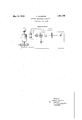
- a particularly simplemancurrent generator 3 is coupled with the'drive I for the picture drum.
- a Kerr cell 6 In the path between photo cell 4 and light source 5 is disposed a Kerr cell 6 provided with the usual optical I system including a polarizer 7 and an analyzer 8.
- the Kerr cell 6 receives its control potential without biasing from the phonic wheel or alternating current generator 3.
- the light of the cell 5,modulated in the doublefrequency of the control frequency impinges diffusely from the picture on to the photo cell which modulates the brightness of the picture points in accordance with the thus produced carrier frequency current.
- This modulated carrier frequency current is then sent in'the usual manner to the transmitting amplifier-10.
- a light source for illuminating a record surface for transmission
- a photoelectric element for converting the light intensities uponelemental areas of the record surface into electrical impulses of proportionate strength
- an electrostatic light valve interposed betweengsaid light source and said record surface for interruptingthe supply oflight upon said surface at a predetermined frequency and producing there by an alternating current output from the photo cell
- generatormeans integral with the record carrying surface for producing in accordance with the rate of transmission of the record subject a progressive rise and. fall of potential upon the electrostatic light valve for regulating the frequency of light interruption thereby.
Landscapes
- Engineering & Computer Science (AREA)
- Multimedia (AREA)
- Signal Processing (AREA)
- Optical Recording Or Reproduction (AREA)
Description
R. SCHMOOK 1,857,745
PICTURE TELEGRAPH APPARATUS May 10, 1932.
Filed Sept. 27, 19:50
INVENTOR RUDOLF sc HMo oK ATTORNEY Patented May 19, 1932 RUDOLF scHMooK, or BERLIn-oHARLorrENBune, eaienraiassidmamo SIEMENS & HALSKE AKTIENGESELLSCHAFT, or SIEMENSSTADT, NEAR BERLIN, GERMANY, A I
CORPORATION OF GERMANY PICTURE TELEGRAPH APPARATUS Application filed September 2'7, 1930, Serial No. 484,810, and in Germany August 10, 1929.
The present invention relates to a system and apparatus for transmitting pictures, motion picture films, images or other likenesses, and is particularly directed to a method and means for introducing a tone or carrier frequency into the light translating element used for converting varying intensities of light and shadow on elemental areas of the transmitted subject into proportionately varied electrical impulses.
Arrangements known in the prior art for picture telegraphy produce the carrier frequency through the modulation of a constant light ray by means of a perforated disk or an oscillograph controlled by alternating current. The perforated disk method has the disadvantage that minimum errors in the spacing of the perforated disk or of the toothed drive result in very disturbing errors in the pictures and that when operating several transmitting channels an exchange of the perforated disk becomes necessary. The modulation by means of an oscillator loop is limited to frequencies below 10,000.
On the other hand it is possible to produce the carrier frequency by causing an alternating current potential to influence a Keri" cell. In this case the alternating current potential is produced by an alternatin current machine coupled with the picture drum, so that in this manner the Kerr cell chops the scanning luminous ray. In the known case the alternating current machine is used ex clusively for the control of the Kerr cell.
According to the invention a considerable simplification of the installation is accomplished by taking the control frequency for the Kerr cell from a phonic wheel existing in the apparatus, for instance, one provided for synchronizing purposes, which takes place after the multiplication. This measure applies to special cases wherein the synchronizing frequency is lower than the.carr1er frequency. If it is for instance desired to synchronize with a synchronizing frequency of 600 cycles, it is necessary to increase this frequency for the purpose of controlling the Kerr cell, in fact to at least double the same since otherwise the carrier frequency becomes too low. In a particularly simplemancurrent generator 3 is coupled with the'drive I for the picture drum. In the path between photo cell 4 and light source 5 is disposed a Kerr cell 6 provided with the usual optical I system including a polarizer 7 and an analyzer 8. The Kerr cell 6 receives its control potential without biasing from the phonic wheel or alternating current generator 3. The light of the cell 5,modulated in the doublefrequency of the control frequency impinges diffusely from the picture on to the photo cell which modulates the brightness of the picture points in accordance with the thus produced carrier frequency current. This modulated carrier frequency current is then sent in'the usual manner to the transmitting amplifier-10.-
Other modifications and changes may sug- .gest themselves to those skilled in the art to which the invention relates and I, therefore,'; believe myself to beentitled to make and-use any and all ofsuch modifications as fall fairly within the spirit and scope of the hereinafter appended claim; wherein I' claim: a
In combination, a light source for illuminating a record surface for transmission, a photoelectric element for converting the light intensities uponelemental areas of the record surface into electrical impulses of proportionate strength, an electrostatic light valve interposed betweengsaid light source and said record surface for interruptingthe supply oflight upon said surface at a predetermined frequency and producing there by an alternating current output from the photo cell, and generatormeans integral with the record carrying surface for producing in accordance with the rate of transmission of the record subject a progressive rise and. fall of potential upon the electrostatic light valve for regulating the frequency of light interruption thereby.
In testimony whereof I atfix my signature.
RUDOLF SCHMOOK.
Lil
Applications Claiming Priority (1)
| Application Number | Priority Date | Filing Date | Title |
|---|---|---|---|
| DE1857745X | 1929-08-10 |
Publications (1)
| Publication Number | Publication Date |
|---|---|
| US1857745A true US1857745A (en) | 1932-05-10 |
Family
ID=7746319
Family Applications (1)
| Application Number | Title | Priority Date | Filing Date |
|---|---|---|---|
| US484810A Expired - Lifetime US1857745A (en) | 1929-08-10 | 1930-09-27 | Picture telegraph apparatus |
Country Status (1)
| Country | Link |
|---|---|
| US (1) | US1857745A (en) |
-
1930
- 1930-09-27 US US484810A patent/US1857745A/en not_active Expired - Lifetime
Similar Documents
| Publication | Publication Date | Title |
|---|---|---|
| GB295601A (en) | Improvements in or relating to means for transmitting radiant energy such as light, and to apparatus for use therewith | |
| US1857745A (en) | Picture telegraph apparatus | |
| US1691147A (en) | Habsy nyqtjist | |
| US1892371A (en) | Method of picture transmission | |
| US2281891A (en) | Picture transmission, television, and the like | |
| US1548895A (en) | Electrical transmission of pictures | |
| US2256530A (en) | Synchronizing system | |
| US2047817A (en) | Picture transmitting system | |
| US1885826A (en) | System of photography employing frequency modulation | |
| US2372762A (en) | Synchronizing system | |
| US2152464A (en) | Television and the like system | |
| US1590270A (en) | Method and apparatus for synchronizing in picture-transmission systems | |
| US1743856A (en) | Picture transmission | |
| US1884288A (en) | Facsimile transmission | |
| US1730772A (en) | Picture telegraphy | |
| US3340360A (en) | Cathode ray photographic printer having positive feedback | |
| US1962417A (en) | Carrier wave television system | |
| GB776129A (en) | Improvements in or relating to secret signalling systems | |
| US2212808A (en) | Signaling method and apparatus | |
| US2204058A (en) | Signaling system | |
| US1505158A (en) | Frequency-control system | |
| US2041822A (en) | Electrooptical system | |
| US2031728A (en) | Electrooptical system | |
| US1661167A (en) | System of picture transmission | |
| US2184743A (en) | Electrooptical system |