US1857728A - Dishwashing machine - Google Patents
Dishwashing machine Download PDFInfo
- Publication number
- US1857728A US1857728A US417056A US41705629A US1857728A US 1857728 A US1857728 A US 1857728A US 417056 A US417056 A US 417056A US 41705629 A US41705629 A US 41705629A US 1857728 A US1857728 A US 1857728A
- Authority
- US
- United States
- Prior art keywords
- pipes
- sink
- secured
- conveyor
- connections
- Prior art date
- Legal status (The legal status is an assumption and is not a legal conclusion. Google has not performed a legal analysis and makes no representation as to the accuracy of the status listed.)
- Expired - Lifetime
Links
Images


Classifications
-
- A—HUMAN NECESSITIES
- A47—FURNITURE; DOMESTIC ARTICLES OR APPLIANCES; COFFEE MILLS; SPICE MILLS; SUCTION CLEANERS IN GENERAL
- A47L—DOMESTIC WASHING OR CLEANING; SUCTION CLEANERS IN GENERAL
- A47L15/00—Washing or rinsing machines for crockery or tableware
- A47L15/24—Washing or rinsing machines for crockery or tableware with movement of the crockery baskets by conveyors
- A47L15/241—Washing or rinsing machines for crockery or tableware with movement of the crockery baskets by conveyors the dishes moving in a horizontal plane
Definitions
- DIsHwAsHING MACHINE Filed Deo. 28,v 1929 7 Sheets-Shao*l 6 May 10, 1932 w. L. LINDGREN DISHWASHING MACHINE Filed Dec. 28, 1929 wie r Patented May 10, 1932 rJNiTED ls'm'ras PATENT eprice WALDEMLB L. LINDGREN, OF WAUKEGAN, ILLINOIS, ⁇ ASSIGNOR F ONE-HALF T0 .TQHN E. EnicssoN, or CHICAGO, 1ILLmois I nIsHWAsHING MACHINE Application led December 28, 1929. Serial' No. 417,056.
- Fig. 1 is a front elevation of the machine go in place in a sink, with'the machine proper in central vertical longitudinal section;
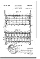
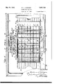
- Figs. 2 and 3 are vertical sections, on a larger scale, on the lines 2 2 and 3 3 of f Fig. 1; i z5 ig. l is a perspective view of one of the wheels going to make up the drum seen 1n vvertical section in Fig. 3; f ⁇ Fig. 5 is a plan view in horizontal section r on the line 5 5 of Fig.v 1; 80
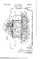
- Fig. 8 is a view similar to Fig. 6, but in section on the line 8 8 of Fig. 1;
- Fig. 9 is a vertical section of the two clearwater spray pipes, showing their connections ce to the liquid supply;
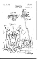
- Fig. 10 is a view, in front elevation, of the faucet connections, with the dish-washing machine removed and the spray pipes in section; i
- Fig. 11 is' a view similar to Fig. l0, but illustrating the parts arranged for the conveyor to move in the opposite direction Without changing the direction of rotation of the motor;
- Fig. 12 is a horizontal section as seen on the Fig. 6 is a sectional View, on an enlargedy Fig. 7 is a perspective View of one corner line 12-12 of Fig. 10, but on a larger scale;
- Fig. 13 is a view in section on the line 13 13O of Fig. 12;
- Fig. 14 is a detail in section on theline 14e-14 of Fig. 13; and 55 Fig. 15 is a detached View, partly in section, of the driving shaft and connections between the motor and the driving shaft of the conveyor.
- My dish-Washing machine is of the type @q adapted to be mounted in the customary sink 20.
- the conveyor which is best shown in Figs. 1 to 6, and 8, is mounted in a frame made up of two longitudinal side pieces 21 and 22, which are spaced apart and rigidly-65 held together by the stationary end ieces l23 and 24. These end pieces 24 prefera ly have the downwardly extending webs 25 at their ends which connect the horizontal ortion with the vertical portions 26.
- the si e piece 7o 22 is preferably imperforate, except for the bearings for the hereinafter mentioned shafts, i but the rear side piece 21 is provided with a pair of lapertures 27 and 28 to receive the lower spray members to be'subsequently de- 75 scribed.
- the three shafts 29, 30 and 31 are journaled in bearings formed in the side pieces, andthe shafts 30- and 31 rotate in operation, although the shaft29 might be stationary with the sprocket wheels 32 on the ends thereof rotating on the shaft, instead of with the shaft.
- the shaft 31 has secured at-its ends, just inside of the side pieces the pair of sprocket wheels 33, and the shaft 30 as secured on it, immediately adjacent the side piece 22, the driving sprocket wheel 34.
- the conveyor belt is preferably constructed of a plurality of horizontal and parallel rods 35 which are connected to form a skeletonbelt by the links 36, which are stamped out of sheet metal and are of thedesign shown in Fig. 1, where it will'v be'seen that each has a. longitudinal slot aiith rounded ends extending substantially the length of the lilik and of a width to receive the-reduced portionof its co-operating rod forming the annular channel 37.
- the slotv has at some point therein, preferably the middle, the enlarged portion 38 which permits the link being slipped over the end of the rod at this point'and moved 100 to the desired channel 37 with which it is to co-operate.
- the side pieces 21 and 22 have projecting inwardly from their upper edge arib 48, which serves to supportthe adjacent links itself from spattering out from over the sink,
- I provide a generally rectangular cover which kconsists of the sheetmetal portion 50,
- curtains 54 are preferably made up of very line metal chains hanging vertically downward in ContactA with.. Y
- each link preferably being the shape of a small ball, such chains being in generaluse for operating electric light fixtures.
- these fiexi ble curtains of this construction do not offer the dishes beneath them, while at the same time they furnish any eii'ectual barrier to the water which would otherwise be splashed out l from the endsfof the cover.
- valves 61 and 62 instead of the customary vertical ⁇ valves, preferably has horizontally operating valves 61 and 62 to open and close the hot an cold water supplies.
- the mixer 60 has extending rearwardly and downwardly ⁇ from the center of the back thereof the outlet extension 65, to which is 1715 to conveniently operate thesefyalves around f j the end of the dish-washing machine, I pref' a erably make the valve stems rectangular and mount o n them the telescopingvalve handles '-gf y12() i turned horizontally to any desired angle, and
- connections 71 and, 72 are turned 0utward and provided with the beveled ends cooperating with the beveled T-heads 77 of the vertical pipes 78 and 79.
- the pipes 78 and 7 9 are secured to the connections 71 and 72 by the screw bolts 80, identical with the screw bolt 73, passing through the beveled disks 81 closing the ends of the T-heads and threaded into apertures formed in the lugs 82 .projecting inwardly from the lower ends of the connec tions 71 and 72.
- rl ⁇ hese connections also have extendin inwardly from the rear side at the bottom t ie substantially strigicircular flanges 83, which are provided with slots 84 by which' they can be secured by the screws 85 to the adjacent half 86 of the casing for the worm gear wheel 87 secured on the adjacent end of a shaft 30a.
- the rear half ⁇ 88 of the casing is secured to the front half by the screws 89,
- the casing contains a recess adapted to receive the worm 90 secured on the shaft 91 extending diagonally upward, the connec tions for the upper end'of which will be described later.
- the pipes 78 and 79 asbest seen in Figs. Scand 9, have formed on their upper and lower ends the forwardly-projecting, verticallyextending beveled valve-seats 92 to receive the downwardly or upwardly extending, as the case may be, valve ends 93 of the pipes 94, 95, 96 and 97, the passage through the tubes and valve ends being so shaped, as clearly seen inFigs 8 and 9, that when the pipes 94, 95,
- the pipes are preferably made in two sections, as seen, which are joined by having their adjacent ends brazed or otherwise secured to the short tubes 98, which havevthe function of reducing the velocity and iow of the water to the necessary extent to accommodate the dish-washing. machine to the particular pressure that is furnished in the location where it is installed.
- the pipes 94 and 95 have soap boxes 99 of the type own in my aforesaid patents as- ⁇ the customary perforations directed downl wardly and upwardly, respectively, so that the soapy water will be thrown downward and upward, respectively, on to the dishes carried between them by the conveyor.
- the tubes 78 and 79 are provided at their lower ends opposite the 'i "valve seats 92 with projections ,which Vpreferably have rubber tips 108 securdthereto and adapted to rest against the rear "wall of thel sink, as shown in Fig. 8.
- the mixer 60 has projecting upwardly from the center thereof the supporting rod 109, which has secured on the upper end thereof the V- shaped bracket 110, with the arms thereof extending outwardly and forwardly and terminatin g in the horizontal portions on which rest the front edge of the base 111 of the motor 112, being secured thereto by the screws 113.
- the pipes 78 and 79 los have-secured t6 lugs formed on the back thereof, near their upper ends, brackets 114 (omitted in Figs. 10 and 11,'but seen in Fig. 6) which have the horizontal upper ends adapted to receive the rear portion of the base ot' the motor 112 secured thereto by 'screws 113.
- the pipes 78 and 79 also have,
- the 'motor v112 is,.of course, provided with wires 118 leading to a suitable 'source'of current supply, and with theswitch secured on the.
- yarmature shaft'120 diid the lj lworin gear wheel 123 securedl onfthelupper end of the shaft extends througlipa bearing 124 onthenpper end of the gear casing 121, and is connected to a flexible shaft 125, which has a handle 126 on the non-rotating covering portion, which handle is adapted to manipulate the scouring I brush 12T, which is detachably secured on the end of the flexible rotating shaft, a bracket 128 being preferably secured on the top of the motor base plate, as seen in Fig. 1, to hold the brush when not in use.
- the brush ' is used in finishing up work that the spray mechanism alone of the washing machine is ⁇ incapable of doing.
- the connections 71 and 72 are reversible on the gear casing 86, 8S, so that the shaft 91 can extend substantially vertically to bring the gear casing onv the right-hand side of the motor, as seen in Fig. 11, or somewhat more inclined to bring the gear casing 121 on the left-hand side of the motor, as seen in Fig. 10, thus reversing the direction of movement of the conveyor without reversing the motor.
- the arrangement shown in Fig. 10 or that shown in Fig. 11 is employed will depend upon the character of the sink and whether' or not it is necessary to have the upper run of the conveyor belt move to the right or left, as the case may be.
- the shaft in the gear casing 86, 88 has secured on its forward end a clutch member 129 with a recess in the center of its clutch face to receive the end of the shaft 30, whichhas the co-operating clutch member 130 secured thereon.
- a dish-Washing machine the combination with 'a frame, of an endless skeleton. conveyor member therein, means for operat- 65 ing said conveyor member, a cover for the upper run of the conveyor member having transverse slots in the top thereof, horizontal spray pipes extending transversely of the cover above said slots, and inverted troughs over said slots, the tops of said troughs removably receiving the spray pipes.
- a worin and a (xo-operating worm wheel in said lower casing and a shaft connecting said casings and secured to the worm wheel in the upper casing and to the worm in the lower casing, said worm wheel in the lower casing being operatively connected to said conveyor mechanism.
- faucet connections for said sink including a hot and cold water mixer, soapy and clear water spray pipes pivotally connected to said faucet connections so that said pipes can be swung horizontally across the conveyor mechanism or parallel to the rear wall of the sink, a bracket supported from said faucet connections, a motor mounted on said bracket, and gearing from the motor to the conveyor mechanism mount- ⁇ ed on said faucet connections.
- said faucet connections including a pair of readily detachable connecting pipes of different lengths but otherwise of the same construction attached tothe mixer and interchangeable so as to bring said soapy and clear water pipes on either side of the mixer, the shorter of the connecting pipes being connected in either adjustment to the clearnvater pipes and the longer to the soapy-water pipes so that the soapy and clear water spray pipes will always be at the proper distance from the articles carried bythe conveyor mechanism.
- faucet connections for said sink including a hot and cold water mixer, soapy and clear wat-er spray pipes pivotally connected to said faucet connections so that said pipes can be swung horizontally across the conveyor mechanism or parallel to the rear wall of the sink, a bracket supported from said faucet connections, a motor mounted on said bracket, and gearing from the motor to the conveyor mechanism mounted on said faucet connections, which connections include a pair of readily-detachable connecting pipes of different lengths but otherwise the same construction attached to the mixer and interchangeable so as tov bring said soapy and clear Water pipes on either side of the mixer, the shorter of the connecting pipes being connected in either adjustment to the clear-water pipes and the longer to the soapy-water pipes so that the soapy and clear water spray pipes will always be at the proper distance from the articles carried by the conveyor mechanism, and said gearing comprising an upper gear casing carried by the armature shaft of the motor and rotatable about the same, a
- a device of the class described the combination with a sink, of hot and cold water supply pipes leading thereto, a mixer connected to said pipes and having therein a pair of cocks having horizontal stems and handles on the stems, a connecting member secured to the mixer between the cocks having outlet ports o'pening into a pair of pipes, said pair of pipes, a soapy-water spray niember, a clear-water spray member, connections from one of said last-mentioned pipes to said soapy-water spray member and from the other to said clear-water Lspray member, said spray members being pivotally mounted by cocks on their ends having vertical axes S0 said spray members can be extended at right angles to or collapsed parallel to the rear wall of the sink, and removable conveying mechanism in said sink.
Landscapes
- Washing And Drying Of Tableware (AREA)
Description
May 10, 1932. w. LINDGREN msHwAsHING MACHINE Filed Dec. 28, 1929 v sheets-sheet 1 KWYN w. LINDGREN 1,857,728
DISHWASHING MACHINE Filed Deo. 2s; 1929 'r sheets-sheet 2 May l0, 1Qv32.
Filed Dec. 28, 1929 7 Sheets-Sheet 5 www .Qi www May 10, 1932. w. L. I INDGREN DI SHWASHING MACHINE Filed Dec. 28, 1929 '7 Sheets-Sheet 4 May 10, 1932- w. 1 LINDGREN DIsHwAsHING MACHINE Filed Deo. 28, 1929 7 sheets-sheet 5 May 10 1932 w. L. LINDGREN y 1,851,728
DIsHwAsHING MACHINE Filed Deo. 28,v 1929 7 Sheets-Shao*l 6 May 10, 1932 w. L. LINDGREN DISHWASHING MACHINE Filed Dec. 28, 1929 wie r Patented May 10, 1932 rJNiTED ls'm'ras PATENT eprice WALDEMLB L. LINDGREN, OF WAUKEGAN, ILLINOIS,` ASSIGNOR F ONE-HALF T0 .TQHN E. EnicssoN, or CHICAGO, 1ILLmois I nIsHWAsHING MACHINE Application led December 28, 1929. Serial' No. 417,056.
'- My invention is concerned with dish wash-- remove certain objections I have found by practice inhere in the aforesaid structures.
The complete machine and its operation will be described in detail, and the novel combinations and features particularly pointed out in the claims.
To illustrate my invention, I have annexed 15 hereto seven sheets of drawings, in which the same reference characters are used to designate identical parts in all the figures, of which,
Fig. 1 is a front elevation of the machine go in place in a sink, with'the machine proper in central vertical longitudinal section;
Figs. 2 and 3 are vertical sections, on a larger scale, on the lines 2 2 and 3 3 of f Fig. 1; i z5 ig. l is a perspective view of one of the wheels going to make up the drum seen 1n vvertical section in Fig. 3; f` Fig. 5 is a plan view in horizontal section r on the line 5 5 of Fig.v 1; 80
scale, on the line 6 6 of Fig. 1;
of the cover in section, showing how it accommodates the upper spray members when the machine is in place;
Fig. 8 is a view similar to Fig. 6, but in section on the line 8 8 of Fig. 1; Fig. 9 is a vertical section of the two clearwater spray pipes, showing their connections ce to the liquid supply;
` Fig. 10 is a view, in front elevation, of the faucet connections, with the dish-washing machine removed and the spray pipes in section; i
Fig. 11 is' a view similar to Fig. l0, but illustrating the parts arranged for the conveyor to move in the opposite direction Without changing the direction of rotation of the motor;
Fig. 12 is a horizontal section as seen on the Fig. 6 is a sectional View, on an enlargedy Fig. 7 is a perspective View of one corner line 12-12 of Fig. 10, but on a larger scale;
Fig. 13 is a view in section on the line 13 13O of Fig. 12;
Fig. 14 is a detail in section on theline 14e-14 of Fig. 13; and 55 Fig. 15 is a detached View, partly in section, of the driving shaft and connections between the motor and the driving shaft of the conveyor. l
My dish-Washing machine is of the type @q adapted to be mounted in the customary sink 20. The conveyor, which is best shown in Figs. 1 to 6, and 8, is mounted in a frame made up of two longitudinal side pieces 21 and 22, which are spaced apart and rigidly-65 held together by the stationary end ieces l23 and 24. These end pieces 24 prefera ly have the downwardly extending webs 25 at their ends which connect the horizontal ortion with the vertical portions 26. The si e piece 7o 22 is preferably imperforate, except for the bearings for the hereinafter mentioned shafts, i but the rear side piece 21 is provided with a pair of lapertures 27 and 28 to receive the lower spray members to be'subsequently de- 75 scribed. The three shafts 29, 30 and 31 are journaled in bearings formed in the side pieces, andthe shafts 30- and 31 rotate in operation, although the shaft29 might be stationary with the sprocket wheels 32 on the ends thereof rotating on the shaft, instead of with the shaft. The shaft 31 has secured at-its ends, just inside of the side pieces the pair of sprocket wheels 33, and the shaft 30 as secured on it, immediately adjacent the side piece 22, the driving sprocket wheel 34.
The conveyor belt is preferably constructed of a plurality of horizontal and parallel rods 35 which are connected to form a skeletonbelt by the links 36, which are stamped out of sheet metal and are of thedesign shown in Fig. 1, where it will'v be'seen that each has a. longitudinal slot aiith rounded ends extending substantially the length of the lilik and of a width to receive the-reduced portionof its co-operating rod forming the annular channel 37. The slotvhas at some point therein, preferably the middle, the enlarged portion 38 which permits the link being slipped over the end of the rod at this point'and moved 100 to the desired channel 37 with which it is to co-operate. With this construction, it will be readily observed that I have produced a simple and inexpensive skeleton carrier which permits the water to be thrown upward through the upper run and on to the dishes and kitchen utensils carried by the skeleton belt.
As I have found that there is a tendency for the knives, forks and spoons to get into the openings in the belt, and assume a vertical position therein, instead of lying on it horizontally, I place between the side pieces and immediately adjacent the under slde of the upper run ofv the belt and the wheels 32, the sheet-metal cross piece 40, which prevents the knives, forks, spoons, etc., from assuming a vertical position and insures their being started on their way extending horizontally on the conveyor. As there may be some displacement of these articles from the action of the jets of water on them, I provide ad- 'acent the under side of the upper run of the elt and the sprocket wheels 33, the sheetmetal cross piece 41, which is secured at its ends to the side pieces and is curved as shown, so that if any end of a knife, fork or spoon should extend through the belt and project downward, it will be cammed back up into place as it arrives over this inclined cross piece 41.
I have previously found much diiiiculty in preventing the knives, forks and spoons from becoming entangled with the belt as it curved around the wheels 33 to the discharge end, and to prevent this possibility, I fill the space between the wheels 33 with a series-of wheels 42, one of which is seen in perspective in Fig.
4, and which have the hubs 43 adapted to be threadedon and preferably secu'red to the shaft 31, and withthe grooves 44 in their-l peripheries to receive the rods 35. The pe I ripheries ofthe disks 42 are, as shown in l Fig.
3 separated `just enough to accommodate the links- 36 as they pass around vthe 'y drum thus formed. This drumlike construe# e. tion prevents any possibility of the knives,v forks and spoons becoming entangled with" the belt at this point, and where they are to be takeny o' of the machine immediately by an attendant, I have the sheet-*metal plate 45 hinged to the edgey of the end piece 24 turned down to the full-line position shown in Fig.
sheet-metal trough 4'?, which is fastened to the cross piece 26 of they end plate 24. v
The side pieces 21 and 22 have projecting inwardly from their upper edge arib 48, which serves to supportthe adjacent links itself from spattering out from over the sink,
I provide a generally rectangular cover which kconsists of the sheetmetal portion 50,
which is of an inverted-trough shape, and is carried by the correspondingly shaped wires or rods 51, which have their ends secured in the lugs 52 projecting horizontally from the side pieces 2l and 22 near their ends. As the varying size dishes must be free to pass under and emerge from the cover, and as it is desirable to prevent spattering out from the ends, lI provide the iexible main curtains 53, de-
pending downwardly at each end and extending clear down tothe conveyor, and their action is reinforced by another pair of similar curtains 54, which, however, do notwextend downwardly so far. These curtains are preferably made up of very line metal chains hanging vertically downward in ContactA with.. Y
the adjacent chains, each link preferably being the shape of a small ball, such chains being in generaluse for operating electric light fixtures. I have found that these fiexi ble curtains of this construction do not offer the dishes beneath them, while at the same time they furnish any eii'ectual barrier to the water which would otherwise be splashed out l from the endsfof the cover. By lifting the Wire ends 51 out of their recesses in the lugs 52, the cover can be removed, if desired.
By reference to Fig. 5, it will be seen that ios the hot'and cold water pipes 55 and -56 ein-.-`
tend from the wall 57 through the side of the v sink 20, and are connected by the special supporting tubes 58 and 59 with a mixer 60,-
whicli, instead of the customary vertical` valves, preferably has horizontally operating valves 61 and 62 to open and close the hot an cold water supplies. In order to enable me 63 and 64, which can be extended, as seen in' Fig. 5, in order to make their operation easier The mixer 60 has extending rearwardly and downwardly `from the center of the back thereof the outlet extension 65, to which is 1715 to conveniently operate thesefyalves around f j the end of the dish-washing machine, I pref' a erably make the valve stems rectangular and mount o n them the telescopingvalve handles '-gf y12() i turned horizontally to any desired angle, and
- which when the washing machine is in use,
' circular apertures 7 0 having beveled edges y to receive the beveled ends of the two tubular connections 71 and 72 which are secured in place 'by the screw bolt 73 passing through an aperture 74 in the upper part of the connection 72, and threaded into the recess 75 formed in the lug 76 on the connection 71 designed to receive said recess. This makes a simple connection sufficiently water-tight for use in such a structure. At the lower` end,`
these connections 71 and, 72 are turned 0utward and provided with the beveled ends cooperating with the beveled T-heads 77 of the vertical pipes 78 and 79. The pipes 78 and 7 9 are secured to the connections 71 and 72 by the screw bolts 80, identical with the screw bolt 73, passing through the beveled disks 81 closing the ends of the T-heads and threaded into apertures formed in the lugs 82 .projecting inwardly from the lower ends of the connec tions 71 and 72. rl`hese connections also have extendin inwardly from the rear side at the bottom t ie substantially seinicircular flanges 83, which are provided with slots 84 by which' they can be secured by the screws 85 to the adjacent half 86 of the casing for the worm gear wheel 87 secured on the adjacent end of a shaft 30a. The rear half `88 of the casing is secured to the front half by the screws 89,
and the casing contains a recess adapted to receive the worm 90 secured on the shaft 91 extending diagonally upward, the connec tions for the upper end'of which will be described later.
The pipes 78 and 79, asbest seen in Figs. Scand 9, have formed on their upper and lower ends the forwardly-projecting, verticallyextending beveled valve-seats 92 to receive the downwardly or upwardly extending, as the case may be, valve ends 93 of the pipes 94, 95, 96 and 97, the passage through the tubes and valve ends being so shaped, as clearly seen inFigs 8 and 9, that when the pipes 94, 95,
to the rear wall of the sink, they are in com- Vwhen they are swung around at right angles thereto and parallel to the rear wall ofthe sink, the water is cut ofi from the horizontal pipes. The pipes are preferably made in two sections, as seen, which are joined by having their adjacent ends brazed or otherwise secured to the short tubes 98, which havevthe function of reducing the velocity and iow of the water to the necessary extent to accommodate the dish-washing. machine to the particular pressure that is furnished in the location where it is installed. j The pipes 94 and 95 have soap boxes 99 of the type own in my aforesaid patents as-` the customary perforations directed downl wardly and upwardly, respectively, so that the soapy water will be thrown downward and upward, respectively, on to the dishes carried between them by the conveyor.
To accommodate the spray pipes 96 and 100, which are provided at their lower sides with the horizontal flanges seen in cross section in Fig. 1,1 secure o n the top of the casing 50 the pair of inverted metal troughs 102, which have the slots103 in the upper sides tliereol:l to receive the-tubular portions of the spray pipes 96 andlOO, as seen in Fig. 1. This construction serves to position the spray pipes relative to the cover V50.`
rlhe conveyor frame -issupported at its front side by the pair ofbrackets 104 extending forwardly from the side frame" 22 and resting on the edge of the sink 20, and is also supported by the pair of brackets 105 projecting rearwardly from the top of the* side piece 21 and having an aperture therein to receive the upwardly extendin end of the lug 106 projecting forwardly rom eachof the pipes 78 and' 7 9. The tubes 78 and 79 are provided at their lower ends opposite the 'i "valve seats 92 with projections ,which Vpreferably have rubber tips 108 securdthereto and adapted to rest against the rear "wall of thel sink, as shown in Fig. 8.
` As seen\-in Figs. 1, 5, 10 and 11, the mixer 60 has projecting upwardly from the center thereof the supporting rod 109, which has secured on the upper end thereof the V- shaped bracket 110, with the arms thereof extending outwardly and forwardly and terminatin g in the horizontal portions on which rest the front edge of the base 111 of the motor 112, being secured thereto by the screws 113. As seen in Fig. 6, the pipes 78 and 79 los have-secured t6 lugs formed on the back thereof, near their upper ends, brackets 114 (omitted in Figs. 10 and 11,'but seen in Fig. 6) which have the horizontal upper ends adapted to receive the rear portion of the base ot' the motor 112 secured thereto by 'screws 113. The pipes 78 and 79 also have,
extending forwardly from the central por-` tions thereof, ears 115, best shown in Figs. 5 and 8, which are secured by screws 116 to box 119, by which it can be turned olf on. Its armature shaft extends reargwardly the ears117 projecting upwardly from the mixery 60.- `The 'motor v112 is,.of course, provided with wires 118 leading to a suitable 'source'of current supply, and with theswitch secured on the. yarmature shaft'120, diid the lj lworin gear wheel 123 securedl onfthelupper end of the shaft extends througlipa bearing 124 onthenpper end of the gear casing 121, and is connected to a flexible shaft 125, which has a handle 126 on the non-rotating covering portion, which handle is adapted to manipulate the scouring I brush 12T, which is detachably secured on the end of the flexible rotating shaft, a bracket 128 being preferably secured on the top of the motor base plate, as seen in Fig. 1, to hold the brush when not in use. Alt will be understood that the brush 'is used in finishing up work that the spray mechanism alone of the washing machine is` incapable of doing.
As clearly shown in Figs. 10 and 11, the connections 71 and 72 are reversible on the gear casing 86, 8S, so that the shaft 91 can extend substantially vertically to bring the gear casing onv the right-hand side of the motor, as seen in Fig. 11, or somewhat more inclined to bring the gear casing 121 on the left-hand side of the motor, as seen in Fig. 10, thus reversing the direction of movement of the conveyor without reversing the motor. Whether the arrangement shown in Fig. 10 or that shown in Fig. 11 is employed will depend upon the character of the sink and whether' or not it is necessary to have the upper run of the conveyor belt move to the right or left, as the case may be.
-The shaft in the gear casing 86, 88 has secured on its forward end a clutch member 129 with a recess in the center of its clutch face to receive the end of the shaft 30, whichhas the co-operating clutch member 130 secured thereon.
lVith the construction shown and described, it will be obvious that when it is desired to remove the dish washer, all that is necessary is to slide the conveyor and its cover casing forwardly, disengaging the clutch mechanism and leaving the spray pipes in their normal position as the conveyor is ,withdrawm after which they can be swung at right angles parallel to the rear wall of the sink, which is then capable of use in the ordinary manner. The conveying mechanism is made of aluminum, and the removable portion is consequentlyL light enough so that it can be readily handled as described above.
The operation of the washing machine when in place will be obvious from the foregoing description of the mechanism.
While I have shown and described my in` vention as embodied in the form which I at present consider best adapted to carry out its purposes, it will be understood that it is capable of modification, and that I do not desire to be limited in the interpretation of the following claims except as may be necessitated by the state of the prior art.
What I claim as new, and desire to secure by Letters Patent of the United States, is:
1. In a dish-Washing machine, the combination with 'a frame, of an endless skeleton. conveyor member therein, means for operat- 65 ing said conveyor member, a cover for the upper run of the conveyor member having transverse slots in the top thereof, horizontal spray pipes extending transversely of the cover above said slots, and inverted troughs over said slots, the tops of said troughs removably receiving the spray pipes. v
2. In a device of the class described, the combination with a sink, of conveyor mechanism supported therein, faucet connections for said sink, soapy and clear water spray ipes pivotally connected to said faucet connections so that said pipes can be swung horizontally across the conveyor mechanism or parallel to the rear wall of the sink, a bracket supported from said faucet connections, a motor mounted on said bracket, and gearing from the motor to the conveyor mechanism mounted on said faucet connections so that the conveyor mechanism can be set to operate in either direction from said motor without reversing it, said gearing comprising an upper gear casing carried by the armature shaft of the motor and rotatable about the same, a worm on said shaft -within said casing, a worm wheel within the casing co-operating with said worm, a lower gear casing carried by said faucet connections and capable of ad justment by rotation through a. small are thereon, a worin and a (xo-operating worm wheel in said lower casing, and a shaft connecting said casings and secured to the worm wheel in the upper casing and to the worm in the lower casing, said worm wheel in the lower casing being operatively connected to said conveyor mechanism.
3. In a device of the class described, the combination with a sink,.of conveyor mechanisms supported therein, faucet connections for said sink including a hot and cold water mixer, soapy and clear water spray pipes pivotally connected to said faucet connections so that said pipes can be swung horizontally across the conveyor mechanism or parallel to the rear wall of the sink, a bracket supported from said faucet connections, a motor mounted on said bracket, and gearing from the motor to the conveyor mechanism mount-` ed on said faucet connections.v said faucet connections including a pair of readily detachable connecting pipes of different lengths but otherwise of the same construction attached tothe mixer and interchangeable so as to bring said soapy and clear water pipes on either side of the mixer, the shorter of the connecting pipes being connected in either adjustment to the clearnvater pipes and the longer to the soapy-water pipes so that the soapy and clear water spray pipes will always be at the proper distance from the articles carried bythe conveyor mechanism.
4. In a device of the class described, the` combination with a sink, of conveyor mech-4 anism supported therein, faucet connections for said sink including a hot and cold water mixer, soapy and clear wat-er spray pipes pivotally connected to said faucet connections so that said pipes can be swung horizontally across the conveyor mechanism or parallel to the rear wall of the sink, a bracket supported from said faucet connections, a motor mounted on said bracket, and gearing from the motor to the conveyor mechanism mounted on said faucet connections, which connections include a pair of readily-detachable connecting pipes of different lengths but otherwise the same construction attached to the mixer and interchangeable so as tov bring said soapy and clear Water pipes on either side of the mixer, the shorter of the connecting pipes being connected in either adjustment to the clear-water pipes and the longer to the soapy-water pipes so that the soapy and clear water spray pipes will always be at the proper distance from the articles carried by the conveyor mechanism, and said gearing comprising an upper gear casing carried by the armature shaft of the motor and rotatable about the same, a-worm on said shaft within said casing, a worm wheel within the casing co-operating with said worm, a lower gearA casing carried by said faucet connections and capable of adjustment by rotation through a small arc thereon, a worm and a co-operating worm wheel in said lower casing, and a shaft connecting'said casings and secured to the worm wheel in the upper casing and to the worm in the lower casing, said worm wheel in the lower casing being operatively connected to said conveyor mechanism.
5. In a device of the class described, the combination with a sink, of hot and cold water supply pipes leading thereto, a mixer connected to said pipes and having therein a pair of cocks having horizontal stems and handles on the stems, a connecting member secured to the mixer between the cocks having outlet ports o'pening into a pair of pipes, said pair of pipes, a soapy-water spray niember, a clear-water spray member, connections from one of said last-mentioned pipes to said soapy-water spray member and from the other to said clear-water Lspray member, said spray members being pivotally mounted by cocks on their ends having vertical axes S0 said spray members can be extended at right angles to or collapsed parallel to the rear wall of the sink, and removable conveying mechanism in said sink. i
6. In a device of the class described, the combination with a sink, of hot and cold water supply pipes leading thereto, a mixer connected to said pipes and having therein a pair of cocks, a connecting member secured to the mixer between the cocks having outlet ports, a pair of pipes opening into said ports, said pipes being readily detachable and of different lengths but otherwise of the same construction and adapted tobe interchanged, a soapy-water spray member, a
clear-water spray member, connections from the longer of said last-mentioned pipes to said soapy-water spray member and from the shorter one to said clear-water spray member so as to bring said soapy and clear Watervspray members on either side of the mixer, the shorter of said connecting pipes being connected in either adjustment to the clear-water spray member and the longer to the soapy-water spray member so that theter supply pipes leading thereto, a mixer connected to said pipes and having therein a pair of cocks, a connecting member secured to the mixer betw/een the cocks having outlet ports opening into a'pair lof pipes, said pair of pipes, which are readily detachable and of different lengths but otherwise of the same construction and adapted to be interchanged, a soapy-water spray member, a clear-water spray member, connections from the longer one of said last-mentioned pipes to saidy soapy-water spray member and from the shorter one to said clear-water spray member so as to bring said soapy and Clearwater spray members on either side of the mixer, the shorter of the connecting pipes being connected in either adjustment to the clear-water spray member and the longer to the soapywater spray member so that the soapyand clear water spray members will always be at the proper distance ,from the articles carried by the conveying mechanism hereinafter specified, said spray members being pivotally mounted by cocks having vertical axes so that said spray members can be extended at right angles to or collapsed parallel with the rear wall of the sink, removable conveying mechanism in said sink, a non-reversible motor mounted on said sink, and driving connections from said motor to said conveying mechanism adapted to be set up so that the conveyor can be driven in either direction as desired.
8. In a device of the `class described, the combination with a sink, of hot and cold water supply pipes leading thereto, a mixer connected to said pipes and having therein a pair of cocks, a connecting member secured to the mixer between the cocks having outlet ports opening into a pair of pipes, said pair of pipes, which are readily detachable and of different lengths but otherwise of the same construction and adapted to be interchanged, a soapy-water spray member, a clear-water spray member, connections from the longer one of said last-mentioned pipes to said soapy-water spray member and from the shorter one to said clear-water spray member so as to bring said soapy and clear water spray members on either side of the mixer, the shorter of the connecting pipes being connected in either adjustment to the clearwater spray member and the longer to the 10 soapy-water spray member so that the soapy l and clear water spraymembers will always be at the proper distance from the articles carried by the conveying mechanism hereinafter specified, said spray members being pivotally '15 mounted by clocks having vertical axes so that said spray members can be extended at right angles to or collapsed parallel with the rear wall of the sink, removable conveying mechanism in said sink, a non-reversible motor mounted on said sink, and driving connections from said motor to said conveying mechanism adapted to be set up so that the conveyor can be driven in either direction as desired, said driving connections comprising an upper gear casing carried ,by the armav ture shaftof the motor and rotatable about the same, a worm on said armature ,shaft Within said casing, a worm wheel. within the casing co-operatin with said Worm, a lower Y gear casing carrie by said pair of pipes and capable of adjustment by rotation through a small arc thereon, a 'Worm and a co-operating worm wheel in said lower casing, and a shaft connecting said casings and secured to thev Worm wheel in the upper casing and to the worm in the lower casing, said worm wheel in the lower casing being operatively connected to said conveyor mechanism. v In witness whereof, I have hereunto set my 4,0, hand this 24th day of December, 1929.
WALDEMAR L. LINDGREN.
lso
Priority Applications (1)
| Application Number | Priority Date | Filing Date | Title |
|---|---|---|---|
| US417056A US1857728A (en) | 1929-12-28 | 1929-12-28 | Dishwashing machine |
Applications Claiming Priority (1)
| Application Number | Priority Date | Filing Date | Title |
|---|---|---|---|
| US417056A US1857728A (en) | 1929-12-28 | 1929-12-28 | Dishwashing machine |
Publications (1)
| Publication Number | Publication Date |
|---|---|
| US1857728A true US1857728A (en) | 1932-05-10 |
Family
ID=23652374
Family Applications (1)
| Application Number | Title | Priority Date | Filing Date |
|---|---|---|---|
| US417056A Expired - Lifetime US1857728A (en) | 1929-12-28 | 1929-12-28 | Dishwashing machine |
Country Status (1)
| Country | Link |
|---|---|
| US (1) | US1857728A (en) |
Cited By (2)
| Publication number | Priority date | Publication date | Assignee | Title |
|---|---|---|---|---|
| US2672149A (en) * | 1950-01-16 | 1954-03-16 | Merlin E Barber | Machine for washing and rinsing glass meter covers and the like |
| US2878820A (en) * | 1956-01-10 | 1959-03-24 | Jr William Carr | Apparatus for cleaning venetian blinds |
-
1929
- 1929-12-28 US US417056A patent/US1857728A/en not_active Expired - Lifetime
Cited By (2)
| Publication number | Priority date | Publication date | Assignee | Title |
|---|---|---|---|---|
| US2672149A (en) * | 1950-01-16 | 1954-03-16 | Merlin E Barber | Machine for washing and rinsing glass meter covers and the like |
| US2878820A (en) * | 1956-01-10 | 1959-03-24 | Jr William Carr | Apparatus for cleaning venetian blinds |
Similar Documents
| Publication | Publication Date | Title |
|---|---|---|
| US2632452A (en) | Combination sink and dishwasher | |
| NO136706B (en) | ||
| US1857728A (en) | Dishwashing machine | |
| US1798428A (en) | Dishwashing machine | |
| US2962741A (en) | Portable electrically operated dish washer | |
| US1046551A (en) | Cutter-casing. | |
| US1633803A (en) | Dishwashing machine | |
| US2342995A (en) | Dishwashing machine | |
| US1915162A (en) | Dishwashing machine | |
| US2017677A (en) | Dishwashing machine | |
| US726016A (en) | Dish-washing machine. | |
| US1816486A (en) | johnson | |
| SE419695B (en) | POTW | |
| US1890520A (en) | Dishwashing machine | |
| US2029563A (en) | Dishwashing machine | |
| US712793A (en) | Cooking vessel. | |
| US734063A (en) | Bottle-washing machine. | |
| US1831774A (en) | Dish washing apparatus | |
| US862662A (en) | Dish-washing machine. | |
| US2446368A (en) | Conveyer type dishwasher | |
| US2671916A (en) | Pot washer | |
| US1367402A (en) | Food-chopper | |
| US1798427A (en) | Dishwashing machine | |
| US1798426A (en) | Dishwashing machine | |
| US1896005A (en) | Dishwashing apparatus |