US1857718A - Ignition magneto - Google Patents
Ignition magneto Download PDFInfo
- Publication number
- US1857718A US1857718A US471819A US47181930A US1857718A US 1857718 A US1857718 A US 1857718A US 471819 A US471819 A US 471819A US 47181930 A US47181930 A US 47181930A US 1857718 A US1857718 A US 1857718A
- Authority
- US
- United States
- Prior art keywords
- core
- magneto
- armature
- distributor
- sleeve
- Prior art date
- Legal status (The legal status is an assumption and is not a legal conclusion. Google has not performed a legal analysis and makes no representation as to the accuracy of the status listed.)
- Expired - Lifetime
Links
- 238000004804 winding Methods 0.000 description 23
- 230000005291 magnetic effect Effects 0.000 description 7
- 239000004020 conductor Substances 0.000 description 4
- 239000007787 solid Substances 0.000 description 3
- 241001602730 Monza Species 0.000 description 1
- 230000004907 flux Effects 0.000 description 1
- 239000011810 insulating material Substances 0.000 description 1
- 230000035939 shock Effects 0.000 description 1
Images
Classifications
-
- H—ELECTRICITY
- H02—GENERATION; CONVERSION OR DISTRIBUTION OF ELECTRIC POWER
- H02K—DYNAMO-ELECTRIC MACHINES
- H02K21/00—Synchronous motors having permanent magnets; Synchronous generators having permanent magnets
- H02K21/12—Synchronous motors having permanent magnets; Synchronous generators having permanent magnets with stationary armatures and rotating magnets
Definitions
- This inventlo'n also comprises means for distributing current generated in said armature and means for removably mounting of the current distributor.
- Figure l is a fragmentary central vertical section of a magneto including a stationary armature according to this invention.
- FIG. 2 is a fragmentary section on line 22 of Figure 1;
- Figure 3 is a planview of the armature removed from the magneto body
- Figure 4 is an end View of the same from left hand as seen in Figure 1;
- Figure 5. is a fragmentary front view of current distributor as .seen from right hand in Figure 1;
- Figure 6 is a fragmentary section on line 66 of Figure 5.
- the magneto illustrated comprises a body 8 in which an inductor 22 is mounted to rotate it. being driven by a shaft 21, and inductor 22 producing a variable magnetic flux in a stationary core 24 contacted by the ends of the armature core 1 as hereinafter described.
- the armature of this invention comprises a laminated core 1 Whose ends are bent in a direction transverse to main body 1 of said core and provide transversely enlarged heads 3, 4; as usually on core body 1 are located primary and secondary windings shown in their whole by reference 2.
- an inverted U-shaped plate 5 On head 3 of core 1 is located an inverted U-shaped plate 5 whose bottom ends abut on side projections 33 of core head 3; screws 6 extending throughout projections 33 engage side legs of U-plate 5 and fasjten said plate 5 on head projections 33 continuous cylindrical or tapering surface MAGNETO 471,819, and in Italy September 5, 1929.
- U- plate 5 has a spring 9 fastened thereon by a rivet 48 said spring 9 being adapted to engage the internal surface of body 8 as illustrated in Figure 1, in which position the spring 9' produces a friction against the body seat for the purpose of holding the armature in position.
- a tapering collar 11 On opposite head 4 of core 1 are located and secured side extensions 10 of a tapering collar 11 engaging a tapering seat 23 of magneto body 8.
- Said collar 11 provides a sleeve 12 having an insulating lining 25 through which extends a conductor 13 leading from winding 2 to current distributor 16 to be hereinafter described, and on said sleeve 12 are mounted stationary rings of ball bearings 14, 14 by which a pinion 15 carrying said current distributor 16 is loosely mounted by a sleeve 38 solid with it by rivets 39 and embracing outer rings of bearings 14, 14; said pinion 15 is driven by a cooperating pinion (not shown) solid with driving shaft 21.
- core 1 and parts 5 and 10 The interconnection of core 1 and parts 5 and 10 is assisted by a strip 17 embodied in the core 1 and providing upturned lugs 18, 19 which arefastened on U-plate 5 and extensions 10 of collar 11 respectively by means of rivets 20.
- the described armature is positioned within the magneto body 8 by inserting surfaces 5', 3" and 10, 11 within cooperating seats 7, 23 of body 8; it is then engaged in position by an expansible ring 26 having a tapering cross section which fits in a groove 27 of similar shape made in body 8, the expansion of said ring 26 forcing the armature in position in its seats.
- the current distributor above referred to consists of a disc 16 of insulating material which carries a central contact 28 having a shell 29 slidable thereon and contacted by a spring 30 forcing it on the end of conductor 13.
- Brushes 31 are fastened on said disc 16, said brushes being connected with contact 28 and intended to supply high voltage current fed by conductor 13 to segments 32 fastened on mg through registering holes 41 provided in pro ections 42 of distributor 16 (see Figures 1,5and 6).
- Each of. studs hasa notch 43 facing the rotary axis of sleeve 38 and distributor 16' has studs 44 fastened thereon on which are engaged wire springs 45 embracing said studs 44 and having a limb abutting on distributor projections 42 and another limb adapted to engage said notches 43 of studs 40 solid with sleeve 38.
- springsv 45 are shifted by fingers as shown by arrows in Figure 5, to release said springs 45 from notches 43 of studs 40; thereafter said distributor 16 is withdrawn longitudinally from sleeve 38 to release it from studs 40.
- the armature provides an integral structure which-may be easily positioned in the magneto body without use of screws or similar means liableto become loose under shocks and vibrations it being safely held in position by expansion ring 26; further no electrical connection is to be made or disconnected because said armature ha"- ing one end of winding 2 connected therewith as usual is in direct contact with magneto mass, and the other end of winding 2 is permanently of distributor 16 which is positioned on and carried by said armature with pinion 15 driving it.
- the distributor is easily located on and removed from the armature, the manipulationsfor its location and removal being simple and its mounting requiring no screw or member subject to become loose.
- a stationary armature for ignition mag- I connected with conductor 13 lead- 'ing to contact 28 V and distri as my invention and desire netos comprising a core, windings on said core, a part fastened on one end of said core, a collar fastened on the other end of said core, said core and part and collar being adapted to engage respectii e seats of the magneto frame, a sleeve extending from said collar, antifriction means on said sleeve, and a current-distributor connected with said winding and carried by said antifriction means.
- a stationary armature for ignition magnetos comprising a core, windin on said a collar fastened on the other end of said core said core and part and collar being adapted to engage respective seats of the magneto frame,
- a sleeve extendin from said collar, a central contact connector with said winding in said sleeve, antifriction means on said sleeve, 1:
- a stationary armature for ignition mag-, netos comprising a core, windings on said core, a part fastened on one end of said core, a collar fastened on the other end of said core, said core and part and collar being adapted to engage respective seats of the magneto. frame, a sleeve extending from said collar, antifriction means on said sleeve, a member carried by said antifriction means, a current distributor connected with said winding, and
- said distributor 'magnetos comprising a core, windings on said core, a part fastened on one end of said core, a collar fastened on the other end of said cure, said core and part and collar being adapted to engage respective seats of the magneto frame, a sleeve extending from said collar,
- antifriction means on said sleeve, a member carried by said antifrict-ion means, a current distributor connected with said winding, cooperating positioning means on said member utor, and spring means interengaging said distributor and member.
- a stationary armature for ignition magnetos comprising a core, windings on said core, a part fastened on one end of said core, a collar fastened on the other end of said core, said core and part and collar being adapted to engage respective seats of the magneto frame, a sleeve extending from said collar, antifriction means on said sleeve, a member carried by said antifriction means, a current distributor connected with said winding and fitting on said member, recessed studs extending from said member throughout said distributor, and resilient members carried by said distributor and engaging said recessed studs.
- a stationary armature for ignition magnetos comprising a core, windings on said core, parts fastened on the ends of said core and adapted to engage the respective seats of the magneto frame, and an expansible ring engaging a groove of said magneto frame and clamping said armature in position.
- a stationary armature for ignition magnetos comprising a core, windings on said core, parts fastened on the ends of said core and adapted to engage the respective seats of the magneto frame, and a tapering cross-section expansible ring engaging a tapering groove of said magneto frame and clamping said armature in position.
- a stationary armature for ignition magnetos comprising a core, windings on said core, parts fastened on the ends of said core and adapted to engage the respective seats of the magneto frame, and a spring member on one of said parts frictionally engaging said magneto frame.
- a stationary armature for ignition magnetos having frames, having seats, and having magneto elements therein comprising a core, windings on said core, parts fastened on the ends of said core forming supports confined by a line comprising within it the transverse profile of said core and windings, said supports being adapted to engage respective seats of the magneto frame for mag netic connection of the armature with magnetic elements in said frame, and resilient means for clamping said armature in said frame.
- a stationary armature for ignition magnetos having frames, having seats and having magneto elements therein, comprising a core, windings on said core, parts fastened onthe ends of said core forming supports confined by a line comprising within it the transverse profile of said core and windings, said supports being adapted to engage respective seats of the magneto frame for magnetic connection of the armature with magnetic elements in said frame, and an expansible ring for clamping said armature in said frame.
- a stationary armature for ignition magnetos having frames, having seats and having magneto elements therein, comprising a core, windings on said core, parts fastened on the ends of said core forming supports in the shape of a surface of revolution comprising within it the transverse profile of said core and windings, said supports being adapted to engage respective seats of the magneto frame for magnetic connection of the armature with magnetic elements in said frame, and resilient means for clamping said armature in said frame.
- a stationary armature for ignition magnetos having frames having seats and having magneto elements and grooves therein comprising a core, windings on said core, a part fastened on one end of said core and forming with it a support adapted to engage a seat in the magneto frame, a collar fastened on the other end of said core and adapted to engage a corresponding seat of the magneto frame, and an expansible ring adapted to be located in a groove of said magneto frame and to engage said collar.
Landscapes
- Engineering & Computer Science (AREA)
- Power Engineering (AREA)
- Ignition Installations For Internal Combustion Engines (AREA)
Description
May 10, 1932. oss -n 1,857,718
IGNITION MAGNETO Filed July 30, i930 LEI Patented May 10, 1932 UNITED STATES PATENT OFFICE GIUSEPPE rossA'rI, or MONZA, ITALY, ASSIGNOR TO FABBRICA ITALIANA MAGNETI. MARELLI soorn'rjl ANONIMA IGNITION Application filed July 30. 1930, Serial No.
- and means for mounting the same in the magneto body.
This inventlo'n also comprises means for distributing current generated in said armature and means for removably mounting of the current distributor.
An embodiment of the present invention is illustrated by way of example on the annexed drawings, and
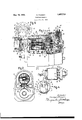
Figure l is a fragmentary central vertical section of a magneto including a stationary armature according to this invention;
Figure 2 is a fragmentary section on line 22 of Figure 1;
Figure 3 is a planview of the armature removed from the magneto body;
Figure 4 is an end View of the same from left hand as seen in Figure 1;
Figure 5.is a fragmentary front view of current distributor as .seen from right hand in Figure 1;
Figure 6 is a fragmentary section on line 66 of Figure 5.
The magneto illustrated comprises a body 8 in which an inductor 22 is mounted to rotate it. being driven by a shaft 21, and inductor 22 producing a variable magnetic flux in a stationary core 24 contacted by the ends of the armature core 1 as hereinafter described.
The armature of this invention comprises a laminated core 1 Whose ends are bent in a direction transverse to main body 1 of said core and provide transversely enlarged heads 3, 4; as usually on core body 1 are located primary and secondary windings shown in their whole by reference 2.
On head 3 of core 1 is located an inverted U-shaped plate 5 whose bottom ends abut on side projections 33 of core head 3; screws 6 extending throughout projections 33 engage side legs of U-plate 5 and fasjten said plate 5 on head projections 33 continuous cylindrical or tapering surface MAGNETO 471,819, and in Italy September 5, 1929.
adapted to engage a seat of magneto body 8 and of stationary core 24.
The intermediate transverse portion of U- plate 5 has a spring 9 fastened thereon by a rivet 48 said spring 9 being adapted to engage the internal surface of body 8 as illustrated in Figure 1, in which position the spring 9' produces a friction against the body seat for the purpose of holding the armature in position.
On opposite head 4 of core 1 are located and secured side extensions 10 of a tapering collar 11 engaging a tapering seat 23 of magneto body 8. Said collar 11 provides a sleeve 12 having an insulating lining 25 through which extends a conductor 13 leading from winding 2 to current distributor 16 to be hereinafter described, and on said sleeve 12 are mounted stationary rings of ball bearings 14, 14 by which a pinion 15 carrying said current distributor 16 is loosely mounted by a sleeve 38 solid with it by rivets 39 and embracing outer rings of bearings 14, 14; said pinion 15 is driven by a cooperating pinion (not shown) solid with driving shaft 21. I
The interconnection of core 1 and parts 5 and 10 is assisted by a strip 17 embodied in the core 1 and providing upturned lugs 18, 19 which arefastened on U-plate 5 and extensions 10 of collar 11 respectively by means of rivets 20.
The described armature is positioned within the magneto body 8 by inserting surfaces 5', 3" and 10, 11 within cooperating seats 7, 23 of body 8; it is then engaged in position by an expansible ring 26 having a tapering cross section which fits in a groove 27 of similar shape made in body 8, the expansion of said ring 26 forcing the armature in position in its seats.
The current distributor above referred to consists of a disc 16 of insulating material which carries a central contact 28 having a shell 29 slidable thereon and contacted by a spring 30 forcing it on the end of conductor 13.
Each of. studs hasa notch 43 facing the rotary axis of sleeve 38 and distributor 16' has studs 44 fastened thereon on which are engaged wire springs 45 embracing said studs 44 and having a limb abutting on distributor projections 42 and another limb adapted to engage said notches 43 of studs 40 solid with sleeve 38.
To release distributor 16 from sleeve 38 after the cover 33-34 removed, springsv 45 are shifted by fingers as shown by arrows in Figure 5, to release said springs 45 from notches 43 of studs 40; thereafter said distributor 16 is withdrawn longitudinally from sleeve 38 to release it from studs 40.
To put distributor 16 again in position, reverse manipulations are made, that is the distributoris inserted on sleeve 38 to engage its holes 41 over studs 40 while springs 45 being held deflected inwardly, and then said springs 45 are released to enable them. to engage notches 43-of studs 40.
Cooperating flanges 46 and 47 are provided distributor l6and sleeve 38 to center and positionsaid distributor on said sleeve.
In the described arrangement the armature provides an integral structure which-may be easily positioned in the magneto body without use of screws or similar means liableto become loose under shocks and vibrations it being safely held in position by expansion ring 26; further no electrical connection is to be made or disconnected because said armature ha"- ing one end of winding 2 connected therewith as usual is in direct contact with magneto mass, and the other end of winding 2 is permanently of distributor 16 which is positioned on and carried by said armature with pinion 15 driving it.
Further the distributor is easily located on and removed from the armature, the manipulationsfor its location and removal being simple and its mounting requiring no screw or member subject to become loose.
Of course the present invention is able of many embodiment-s lying within appended claims.
What I claim to secure by United States Letters Patent 1. A stationary armature for ignition mag- I connected with conductor 13 lead- 'ing to contact 28 V and distri as my invention and desire netos comprising a core, windings on said core, a part fastened on one end of said core, a collar fastened on the other end of said core, said core and part and collar being adapted to engage respectii e seats of the magneto frame, a sleeve extending from said collar, antifriction means on said sleeve, and a current-distributor connected with said winding and carried by said antifriction means.
2. A stationary armature for ignition magnetos comprising a core, windin on said a collar fastened on the other end of said core said core and part and collar being adapted to engage respective seats of the magneto frame,
a sleeve extendin from said collar, a central contact connector with said winding in said sleeve, antifriction means on said sleeve, 1:
current distributor and driving means therefor removably mounted on said antifriction means and a contact in said distributor engaging said sleeve central contact.
4. A stationary armature for ignition mag-, netos, comprising a core, windings on said core, a part fastened on one end of said core, a collar fastened on the other end of said core, said core and part and collar being adapted to engage respective seats of the magneto. frame, a sleeve extending from said collar, antifriction means on said sleeve, a member carried by said antifriction means, a current distributor connected with said winding, and
spring means interengaging said distributor 'magnetos comprising a core, windings on said core, a part fastened on one end of said core, a collar fastened on the other end of said cure, said core and part and collar being adapted to engage respective seats of the magneto frame, a sleeve extending from said collar,
antifriction means on said sleeve, a member carried by said antifrict-ion means, a current distributor connected with said winding, cooperating positioning means on said member utor, and spring means interengaging said distributor and member.
6. A stationary armature for ignition magnetos, comprising a core, windings on said core, a part fastened on one end of said core, a collar fastened on the other end of said core, said core and part and collar being adapted to engage respective seats of the magneto frame, a sleeve extending from said collar, antifriction means on said sleeve, a member carried by said antifriction means, a current distributor connected with said winding and fitting on said member, recessed studs extending from said member throughout said distributor, and resilient members carried by said distributor and engaging said recessed studs.
7. A stationary armature for ignition magnetos, comprising a core, windings on said core, parts fastened on the ends of said core and adapted to engage the respective seats of the magneto frame, and an expansible ring engaging a groove of said magneto frame and clamping said armature in position.
8. A stationary armature for ignition magnetos, comprising a core, windings on said core, parts fastened on the ends of said core and adapted to engage the respective seats of the magneto frame, and a tapering cross-section expansible ring engaging a tapering groove of said magneto frame and clamping said armature in position.
9. A stationary armature for ignition magnetos, comprising a core, windings on said core, parts fastened on the ends of said core and adapted to engage the respective seats of the magneto frame, and a spring member on one of said parts frictionally engaging said magneto frame.
10. A stationary armature for ignition magnetos having frames, having seats, and having magneto elements therein comprising a core, windings on said core, parts fastened on the ends of said core forming supports confined by a line comprising within it the transverse profile of said core and windings, said supports being adapted to engage respective seats of the magneto frame for mag netic connection of the armature with magnetic elements in said frame, and resilient means for clamping said armature in said frame.
11. A stationary armature for ignition magnetos having frames, having seats and having magneto elements therein, comprising a core, windings on said core, parts fastened onthe ends of said core forming supports confined by a line comprising within it the transverse profile of said core and windings, said supports being adapted to engage respective seats of the magneto frame for magnetic connection of the armature with magnetic elements in said frame, and an expansible ring for clamping said armature in said frame.
12. A stationary armature for ignition magnetos having frames, having seats and having magneto elements therein, comprising a core, windings on said core, parts fastened on the ends of said core forming supports in the shape of a surface of revolution comprising within it the transverse profile of said core and windings, said supports being adapted to engage respective seats of the magneto frame for magnetic connection of the armature with magnetic elements in said frame, and resilient means for clamping said armature in said frame.
13. A stationary armature for ignition magnetos having frames having seats and having magneto elements and grooves therein, comprising a core, windings on said core, a part fastened on one end of said core and forming with it a support adapted to engage a seat in the magneto frame, a collar fastened on the other end of said core and adapted to engage a corresponding seat of the magneto frame, and an expansible ring adapted to be located in a groove of said magneto frame and to engage said collar.
In testimony whereof I have signed my name to this specification.
GIUSEPPE FOSSATI.
Applications Claiming Priority (1)
| Application Number | Priority Date | Filing Date | Title |
|---|---|---|---|
| IT1857718X | 1929-09-05 |
Publications (1)
| Publication Number | Publication Date |
|---|---|
| US1857718A true US1857718A (en) | 1932-05-10 |
Family
ID=11434747
Family Applications (1)
| Application Number | Title | Priority Date | Filing Date |
|---|---|---|---|
| US471819A Expired - Lifetime US1857718A (en) | 1929-09-05 | 1930-07-30 | Ignition magneto |
Country Status (1)
| Country | Link |
|---|---|
| US (1) | US1857718A (en) |
-
1930
- 1930-07-30 US US471819A patent/US1857718A/en not_active Expired - Lifetime
Similar Documents
| Publication | Publication Date | Title |
|---|---|---|
| US2513226A (en) | Field structure for rotating electrical equipement | |
| US2059518A (en) | Magneto rotor | |
| US2520828A (en) | Motor-generator construction | |
| KR20110083699A (en) | Rotary coupling device with wear compensation structure | |
| US1857718A (en) | Ignition magneto | |
| US2479455A (en) | Electric motor | |
| US10038350B2 (en) | DC motor | |
| US643095A (en) | Magneto-electric lighting apparatus for bicycles. | |
| US1923864A (en) | Brush plate assembly | |
| US2507573A (en) | Electromagnetic friction device | |
| US1844218A (en) | Ignition magneto | |
| US1405536A (en) | Electrical system | |
| US2241073A (en) | Dynamoelectric machine | |
| US2396950A (en) | Electric brake | |
| US2487180A (en) | Manufacture of imbricated electromagnetic elements | |
| GB356471A (en) | Improvements in or relating to armatures for ignition magnetos | |
| US1993824A (en) | Magneto-electric machine | |
| US2322994A (en) | Ignition magneto | |
| US2080018A (en) | Magnetic rotor | |
| US2233946A (en) | Magneto | |
| US1856146A (en) | Dynamo electric machine | |
| US1262587A (en) | Dynamo-electric machine. | |
| US2024161A (en) | Magneto generator | |
| US2048896A (en) | Magneto | |
| JP2519143Y2 (en) | Reverse power supply type cord reel |