US1857597A - Nautical instrument - Google Patents
Nautical instrument Download PDFInfo
- Publication number
- US1857597A US1857597A US244387A US24438728A US1857597A US 1857597 A US1857597 A US 1857597A US 244387 A US244387 A US 244387A US 24438728 A US24438728 A US 24438728A US 1857597 A US1857597 A US 1857597A
- Authority
- US
- United States
- Prior art keywords
- sphere
- compass
- balls
- cylinder
- ship
- Prior art date
- Legal status (The legal status is an assumption and is not a legal conclusion. Google has not performed a legal analysis and makes no representation as to the accuracy of the status listed.)
- Expired - Lifetime
Links
- 239000011295 pitch Substances 0.000 description 8
- 239000012780 transparent material Substances 0.000 description 2
- 229920002160 Celluloid Polymers 0.000 description 1
- 239000011521 glass Substances 0.000 description 1
- 239000005337 ground glass Substances 0.000 description 1
- 230000004048 modification Effects 0.000 description 1
- 238000012986 modification Methods 0.000 description 1
- 230000000284 resting effect Effects 0.000 description 1
- 230000000717 retained effect Effects 0.000 description 1
- 239000000126 substance Substances 0.000 description 1
Images
Classifications
-
- G—PHYSICS
- G01—MEASURING; TESTING
- G01C—MEASURING DISTANCES, LEVELS OR BEARINGS; SURVEYING; NAVIGATION; GYROSCOPIC INSTRUMENTS; PHOTOGRAMMETRY OR VIDEOGRAMMETRY
- G01C17/00—Compasses; Devices for ascertaining true or magnetic north for navigation or surveying purposes
- G01C17/02—Magnetic compasses
- G01C17/04—Magnetic compasses with north-seeking magnetic elements, e.g. needles
- G01C17/10—Comparing observed direction with north indication
- G01C17/12—Comparing observed direction with north indication by sighting means, e.g. for surveyors' compasses
Definitions
- a further object of the invention is an apparatus for indieating and recording the roll and pitch of the ship.
- a sphere is supported by means of a circle of balls of smaller
- the balls are mounted upon a support which rests upon the deck of a ship.
- a rigid pendulum has one end attached to the sphere and extends through the circle of balls.
- a compass or .other instrument is mounted on the sphere diametrically opposite the pendulum.
- the compass may be provided with a plurality of telescoping arms carrying marking means at their ends.
- a cylinder of paper or the like may enclose the compass and be so arranged as to be engaged by the marking means. Relative movement of the cylinder and compass causes the marking means to produce up and down lines on the cylinder, thus registering the roll or pitch of the ship. As the sphere is free to move in all directions an accurate record of the ships motion may be obtained.
- Fig. 2 is a sectional view of one of the telescoping arms
- Fig. 3 is an enlarged detail view of the marking means.
- Fig. 4 is a perspective of a modified arrangement of the sphere supporting balls.
- a 10 represents a standard which is adapted to stand on the deck of a ship and be permanently attached thereto. At the upper end of the standard 10 is provided a circular recess 11 in which is mounted a series of balls 12, these balls being of the type used in antifriction bearing.
- a sphere 13 rests upon the balls 12 and is capable of universal movement.
- a pendulum 14 has one end fastened to the sphere 13 and carries at its other end a weight 15 which is adjustable lengthwise of the pendulum.
- a support 16 is nounted on the sphere 13 by means of a stud 17 which extends into a socket in the sphere 13. The sockets into which the stud 17 and pendulum 14 project are diametrically opposite each other.
- a set screw 18 is provided for clamping the stud 17 in the sphere.
- the compass 19 is carried by the support 16 and may be of any well known type of compass.
- An electric lamp 20 is arranged below the compass 19 in the event that the compass is of the type having a ground glass bottom.
- the device above described supports the compass and maintains the same in substantially horizontal position at all times.
- the pendulum 14 tends to remain vertical despite the roll or pitch of the ship and as the axis of the compass is parallel to the pendulum the compass itself is maintained substantially horizontal at all times. Friction may be reduced to a minimum and the advantages of universal movement retained by utilizing five balls mounted in a race, as shown in Fig. 4. The use of five balls while advantageous because of the reduction in friction is not essential to the invention.
- This means may comprise a cylindrical shell 21 supported by the standard 20 and enclosing the compass,
- a cylinder 22 of paper or the like or the shell itself may be composed of a transparent substance such as celluloid, glass or the like.
- a plurality of telescoping arms 23 carried by the compass 19 extend radially therefrom. In the outer end of each arm is rotatably mounted a small ball 25 and is engaged by an ink pad 26'.
- An ink reservoir 27 is carried by each arm and conveys ink to the pad 26.
- a spring 28 maintains the ink pad 26in c0ntact with ball 25 and a spring 29 presses the movable part of the telescoping arm outwardly so as to maintain the ball 25 in contact with the paper cylinder 23' at all times.
- the shell 21 is of transparent material and the cylinder 22. may be provided with vertical lines as shown indicating the points of the compass and with horizontal circles indicating degrees of rolLthese linings being arranged below or above a zero circle which indicates the position when the ship is at rest. By means of these lines an accurate indication may be obtained of the extent and direction of the movement of the ship.
- the ink reservoirs 27. may be omitted or the ink drained therefrom. This will permit observation of. the arms through the transparent matter without tracing any record on the cylinder.
- the support may be utilized in connection with various other instruments or devices.
- it may be utilized as a support for a telescope, abed, a chair, an operating table or platform or as a support for machine or other types of guns mounted on ships, motor trucks or railway carriages.
- it may be made use of wherever it is desirable to maintain an instrument, device or apparatus in a predetermined position regardless of the motion of the structure upon which it is mounted.
- various structural modifications may be made without inany way departing. from the spirit of the invention as defined-in the appended claims.
- An apparatus of the character described comprising a sphere, an annular member supporting said sphere, a pendulum suspended from said sphere, means for supporting a cylinder of paper or the like around said sphere and self-adjusting marking members supported by said sphere and having their ends engaging said cylinder.
- An apparatus of the character described comprising a standard annular row of balls supported thereby, a sphere resting on said balls, a pendulum suspended from said sphere, a compass carried by said sphere, means for supporting a cylinder of paper or the like, and marking members carried by said compass and engagin said cylinder.
Landscapes
- Engineering & Computer Science (AREA)
- Radar, Positioning & Navigation (AREA)
- Remote Sensing (AREA)
- Physics & Mathematics (AREA)
- General Physics & Mathematics (AREA)
- Indicating Or Recording The Presence, Absence, Or Direction Of Movement (AREA)
Description
May 10, 1932. w. LILLY NAUTICAL INSTRUMENT Filed Jan. 4, 1928 diameter than the sphere.
Patented May 10, 1932 UNITED STATES PATENT OFFICE WILLIAM LILLY, OF NEW YORK, N. Y.
NAUTICAL INSTRUMENT Application filed January 4, 1928.
a compass in such manner that it is main-.
tained horizontal at all times. A further object of the invention is an apparatus for indieating and recording the roll and pitch of the ship. These two objects may be embodied in a single device.
According to this invention a sphere is supported by means of a circle of balls of smaller The balls are mounted upon a support which rests upon the deck of a ship. A rigid pendulum has one end attached to the sphere and extends through the circle of balls. A compass or .other instrument is mounted on the sphere diametrically opposite the pendulum. Thus when the ship rolls or pitches or both pitches and rolls the pendulum exerts movement of force on the sphere tending to hold the latter ,in such position that the pendulum is vertical. Thus although there is relative movement of the sphere and the balls supporting the same the compass and the other instrument mounted on thesphere remains hori- .zontal.
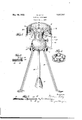
The compass may be provided with a plurality of telescoping arms carrying marking means at their ends. A cylinder of paper or the like may enclose the compass and be so arranged as to be engaged by the marking means. Relative movement of the cylinder and compass causes the marking means to produce up and down lines on the cylinder, thus registering the roll or pitch of the ship. As the sphere is free to move in all directions an accurate record of the ships motion may be obtained. Other objects, novel features, and advantages of the invention will be apparent from the following description and accompanying drawings, wherein Fig. 1 is a perspective view partially in Serial No. 244,387.
section of an apparatus embodying the invention;
Fig. 2 is a sectional view of one of the telescoping arms, and
Fig. 3 is an enlarged detail view of the marking means.
Fig. 4 is a perspective of a modified arrangement of the sphere supporting balls.
10 represents a standard which is adapted to stand on the deck of a ship and be permanently attached thereto. At the upper end of the standard 10 is provided a circular recess 11 in which is mounted a series of balls 12, these balls being of the type used in antifriction bearing. A sphere 13 rests upon the balls 12 and is capable of universal movement. A pendulum 14 has one end fastened to the sphere 13 and carries at its other end a weight 15 which is adjustable lengthwise of the pendulum. A support 16 is nounted on the sphere 13 by means of a stud 17 which extends into a socket in the sphere 13. The sockets into which the stud 17 and pendulum 14 project are diametrically opposite each other. A set screw 18 is provided for clamping the stud 17 in the sphere. The compass 19 is carried by the support 16 and may be of any well known type of compass. An electric lamp 20 is arranged below the compass 19 in the event that the compass is of the type having a ground glass bottom.
The device above described supports the compass and maintains the same in substantially horizontal position at all times. The pendulum 14 tends to remain vertical despite the roll or pitch of the ship and as the axis of the compass is parallel to the pendulum the compass itself is maintained substantially horizontal at all times. Friction may be reduced to a minimum and the advantages of universal movement retained by utilizing five balls mounted in a race, as shown in Fig. 4. The use of five balls while advantageous because of the reduction in friction is not essential to the invention.
Means are also provided for recording the roll or pitch of the ship. This means may comprise a cylindrical shell 21 supported by the standard 20 and enclosing the compass,
on the inner surface of which is provided a cylinder 22 of paper or the like or the shell itself may be composed of a transparent substance such as celluloid, glass or the like. A plurality of telescoping arms 23 carried by the compass 19 extend radially therefrom. In the outer end of each arm is rotatably mounted a small ball 25 and is engaged by an ink pad 26'. An ink reservoir 27 is carried by each arm and conveys ink to the pad 26. A spring 28 maintains the ink pad 26in c0ntact with ball 25 and a spring 29 presses the movable part of the telescoping arm outwardly so as to maintain the ball 25 in contact with the paper cylinder 23' at all times. Thus upon relative movement of the sphere 13 and its support there is produced relative movement of the arms 23 and the shell 21. As a result balls 25 trace lines on the paper cylinder 22 thus indicating the roll or the pitch of the ship. Because of the fact that the sphere 13 is mounted for universal movement and there are provided a plurality of arms 23 an accuratev indication is obtained of the movement of the ship Whether it be a pitch or a roIl,.or a combination of both. Although two springs 28 and 29 have been used, it is apparent that a single spring might be used both to maintain the ink pad 26 in contact with the ball 25 and to press the movable section of the telescoping arm outwardly.
The shell 21 is of transparent material and the cylinder 22. may be provided with vertical lines as shown indicating the points of the compass and with horizontal circles indicating degrees of rolLthese linings being arranged below or above a zero circle which indicates the position when the ship is at rest. By means of these lines an accurate indication may be obtained of the extent and direction of the movement of the ship. In the event that the shell 21 is made of transparent material the ink reservoirs 27. may be omitted or the ink drained therefrom. This will permit observation of. the arms through the transparent matter without tracing any record on the cylinder.
Although the invention has been described in connection with nautical instruments, it is apparent that the support may be utilized in connection with various other instruments or devices. For example, it may be utilized as a support for a telescope, abed, a chair, an operating table or platform or as a support for machine or other types of guns mounted on ships, motor trucks or railway carriages. In fact it may be made use of wherever it is desirable to maintain an instrument, device or apparatus in a predetermined position regardless of the motion of the structure upon which it is mounted. It is of course apparent that various structural modifications may be made without inany way departing. from the spirit of the invention as defined-in the appended claims.
I claim:
1. An apparatus of the character described comprising a sphere, an annular member supporting said sphere, a pendulum suspended from said sphere, means for supporting a cylinder of paper or the like around said sphere and self-adjusting marking members supported by said sphere and having their ends engaging said cylinder.
2. An apparatus of the character described comprising a standard annular row of balls supported thereby, a sphere resting on said balls, a pendulum suspended from said sphere, a compass carried by said sphere, means for supporting a cylinder of paper or the like, and marking members carried by said compass and engagin said cylinder.
In testimony whereof, have signed my name to this specification.
WILLIAM LILLY.
Priority Applications (1)
| Application Number | Priority Date | Filing Date | Title |
|---|---|---|---|
| US244387A US1857597A (en) | 1928-01-04 | 1928-01-04 | Nautical instrument |
Applications Claiming Priority (1)
| Application Number | Priority Date | Filing Date | Title |
|---|---|---|---|
| US244387A US1857597A (en) | 1928-01-04 | 1928-01-04 | Nautical instrument |
Publications (1)
| Publication Number | Publication Date |
|---|---|
| US1857597A true US1857597A (en) | 1932-05-10 |
Family
ID=22922520
Family Applications (1)
| Application Number | Title | Priority Date | Filing Date |
|---|---|---|---|
| US244387A Expired - Lifetime US1857597A (en) | 1928-01-04 | 1928-01-04 | Nautical instrument |
Country Status (1)
| Country | Link |
|---|---|
| US (1) | US1857597A (en) |
Cited By (1)
| Publication number | Priority date | Publication date | Assignee | Title |
|---|---|---|---|---|
| US2484298A (en) * | 1947-03-27 | 1949-10-11 | Nielsen A C Co | Stylus for graphic recording |
-
1928
- 1928-01-04 US US244387A patent/US1857597A/en not_active Expired - Lifetime
Cited By (1)
| Publication number | Priority date | Publication date | Assignee | Title |
|---|---|---|---|---|
| US2484298A (en) * | 1947-03-27 | 1949-10-11 | Nielsen A C Co | Stylus for graphic recording |
Similar Documents
| Publication | Publication Date | Title |
|---|---|---|
| CN110260116B (en) | Geographical mapping device convenient to carry and operate | |
| US5076444A (en) | Crayon housing apparatus | |
| US1857597A (en) | Nautical instrument | |
| US2857674A (en) | Protractor, compass and ruler | |
| US2089439A (en) | Adjustable tripod head | |
| US2958132A (en) | Centerless compass for making circles | |
| US1887437A (en) | Micrometer | |
| US2681783A (en) | Self-leveling device | |
| JPS57189022A (en) | Load detector | |
| CN108720143B (en) | Clothing design volume body device | |
| US1897580A (en) | Grooved supporting fork for globes | |
| US4089118A (en) | Course indicator | |
| US2984014A (en) | Instruments for measuring the curvature of curved surfaces | |
| US3156067A (en) | Ball balance testing device | |
| GB294456A (en) | Improvements in leveling devices | |
| US2217008A (en) | Drafting apparatus | |
| SU47085A1 (en) | Circle Drawer | |
| SU59319A1 (en) | Instrument for recording vessel tilt angles for determining metacentric heights | |
| US2408343A (en) | Level | |
| US1055303A (en) | Ellipsograph. | |
| US2697280A (en) | Instrument for locating celestial bodies | |
| US390550A (en) | Testing-machine | |
| US917594A (en) | Automatic display advertising device. | |
| US732258A (en) | Automatic leveling instrument. | |
| US3290782A (en) | Plane table instrument |