US1857591A - Storage battery - Google Patents
Storage battery Download PDFInfo
- Publication number
- US1857591A US1857591A US37948A US3794825A US1857591A US 1857591 A US1857591 A US 1857591A US 37948 A US37948 A US 37948A US 3794825 A US3794825 A US 3794825A US 1857591 A US1857591 A US 1857591A
- Authority
- US
- United States
- Prior art keywords
- envelope
- strips
- storage battery
- active
- unit
- Prior art date
- Legal status (The legal status is an assumption and is not a legal conclusion. Google has not performed a legal analysis and makes no representation as to the accuracy of the status listed.)
- Expired - Lifetime
Links
- 239000000463 material Substances 0.000 description 11
- 239000011149 active material Substances 0.000 description 6
- 239000002184 metal Substances 0.000 description 5
- 229910052751 metal Inorganic materials 0.000 description 5
- PXHVJJICTQNCMI-UHFFFAOYSA-N Nickel Chemical compound [Ni] PXHVJJICTQNCMI-UHFFFAOYSA-N 0.000 description 4
- 238000010276 construction Methods 0.000 description 3
- 239000012212 insulator Substances 0.000 description 3
- UQSXHKLRYXJYBZ-UHFFFAOYSA-N Iron oxide Chemical compound [Fe]=O UQSXHKLRYXJYBZ-UHFFFAOYSA-N 0.000 description 2
- 238000010410 dusting Methods 0.000 description 2
- 229910052759 nickel Inorganic materials 0.000 description 2
- ZLMJMSJWJFRBEC-UHFFFAOYSA-N Potassium Chemical compound [K] ZLMJMSJWJFRBEC-UHFFFAOYSA-N 0.000 description 1
- 229910000831 Steel Inorganic materials 0.000 description 1
- 239000012670 alkaline solution Substances 0.000 description 1
- 230000000694 effects Effects 0.000 description 1
- 150000002739 metals Chemical class 0.000 description 1
- 230000004048 modification Effects 0.000 description 1
- 238000012986 modification Methods 0.000 description 1
- 230000002035 prolonged effect Effects 0.000 description 1
- 239000010959 steel Substances 0.000 description 1
- 239000000126 substance Substances 0.000 description 1
Images

Classifications
-
- H—ELECTRICITY
- H01—ELECTRIC ELEMENTS
- H01M—PROCESSES OR MEANS, e.g. BATTERIES, FOR THE DIRECT CONVERSION OF CHEMICAL ENERGY INTO ELECTRICAL ENERGY
- H01M4/00—Electrodes
- H01M4/02—Electrodes composed of, or comprising, active material
- H01M4/64—Carriers or collectors
- H01M4/70—Carriers or collectors characterised by shape or form
- H01M4/76—Containers for holding the active material, e.g. tubes, capsules
- H01M4/762—Porous or perforated metallic containers
-
- Y—GENERAL TAGGING OF NEW TECHNOLOGICAL DEVELOPMENTS; GENERAL TAGGING OF CROSS-SECTIONAL TECHNOLOGIES SPANNING OVER SEVERAL SECTIONS OF THE IPC; TECHNICAL SUBJECTS COVERED BY FORMER USPC CROSS-REFERENCE ART COLLECTIONS [XRACs] AND DIGESTS
- Y02—TECHNOLOGIES OR APPLICATIONS FOR MITIGATION OR ADAPTATION AGAINST CLIMATE CHANGE
- Y02E—REDUCTION OF GREENHOUSE GAS [GHG] EMISSIONS, RELATED TO ENERGY GENERATION, TRANSMISSION OR DISTRIBUTION
- Y02E60/00—Enabling technologies; Technologies with a potential or indirect contribution to GHG emissions mitigation
- Y02E60/10—Energy storage using batteries
Definitions
- STORAGE BATTERY The presentinvention rel-atteste se-oesliled. ing thewemployment ofdiiferent i l alkaline. batteries, in which the positive pole plate.A includes, for eXample, ⁇ hydtoxide, and in wlri ela tlrenegative. pole; plate includes,
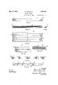
- the principal obg ects of the present inven-v tion are, firs-t, te provide, a. battery of coni-V m paratively prolonged life-land o-fincreased capacity; secondi, toJ simplify and; improve features of construction; arrangement andV En the following description reference Willi be made tothe aecompanyingdrawings ing part hereof and inwhieli ⁇ 25 f Figure l is an elevational view of' al plate or electrode embodying features of the inven# tion.
- Fig. 2- is. a top or planvievv of a pair of plates or electrodes embodying features of 30 the invention and which may be considered to be of opposite sign and inoperative relation.
- Fig. 8 is a sectional view taken on the line 3-3 of Fig. l. i
- Fig. l is a sectional View taken on the line 35 3l- 4f of Fig. l.
- Fig. 5 is a side view of one of the units of the plate or electrode.
- Figs. 6, 7 and 8 are views illustrative of 4 I the internal construction ofa unit; Fig. 6 being a top View, Fig. 7 a side View, and Fig. 8 an end View.
- Fig. 9 is a plan Viev of the envelope or tube blank.
- Fig. l() is a vievv of the same partially folded.
- Fig. 11 is a View7 illustrating in section the folding steps ofthe tube aroundits contents.
- Fig. l2 is an enlarged sectional view showopenings difl'erent parts' of the unit.
- active inateri al may be made by dusting the active 1na terialor material to become aetive onto one strip then ay seeond strip may be laid upon the lirst stripl similarlydusted, and so on until the assemblage complete, and pressure or'aeonsloliolation may Well be ap.-
- The: dusting maybe oonnedl tothe i l' middle parts ⁇ of the strips, orit may ⁇ becontinued to the; ends, and thelatterV casethe end portions oftheunit. may begfreed from aetive material or. materialto. become active, for example, as rset .forth in eompani-on Fat ⁇ ent te W. H.-Bfancroft, SperialfNo. 1-,585552L
- the assemblage of strips end-activemateral or material tol become acti-ve is-plaeed irren envelope or tube 4, which may be Vof Ithe' seine or similar metals employed inrnaling'the strips.
- the envelope provides fo" raminousv portions or panels surrounded by' Y k CD imperforate portions.
- the envelope 4 is folded around the described assemblage, for
- Fig. 11 As indicated in Fig. 11, with the result that it is rectangular in cross-section and is secured by a lock fold 5.
- the holes 6 in the envelope may be punched without the removal of metal leaving a kind of burr which, facing the active material, tends to retain it. It will of course be understood that in the assemblage the parts are subject to consolidar tion and pressure.
- the unit is pinched, Fig. 5, and in this way the end portions of the strips and the end portions of the envelope are brought into intimate association preventing material from working out Y of the' units. If desired bands 8 encircling the unit may be provided.
- T he pinched ends 7 of the unit afford a means by which the end'terminals 9 and'10 may be secured to them providing definite contact throughout the unit as a path for current.
- the terminals are of zigzag form and are provided with tabs 11 by whichthey are Vclamped tothe ends 7.
- 12 is a terminal post connected with the terminal 10.
- 13 are insulators as of rubber or rubber material as they arevshown asv of quatrefoil form in cross-section.
- One advantage of this is that an imperforate corner of each'of the adjacent units makes practically line contact with the insulator thus exposing substantially all of the faces of the adjacent units for Athe occurrence of battery actionpor the passage ofcurrent.
- the described lshape-of* the insulators 13 ⁇ also permits of their being held so as in effect to be ⁇ unitary parts Vof the Vplate Vor electrode.
- active material is intended to include material which becomes active upon the operation of the storage battery.
- An alkaline storage battery plate or Velectrode including a unit comprising a rectangular perforated metallic envelope having internal burrs at the perforations, foraminous metal strips having smooth faces arranged in confronting relation and cotermi-V nous with the envelope, and active material applied toand between the middle portions of said strips leaving the ends bare, and the bare ends of the strips andV wall of the -envelope being pinchedvtogethen, substantially as described.
- a storage battery electrode comprising a plurality of similar tubularunits of approximately square cross'section, each unit having an envelopeformed ofra single metallic sheet folded into tubular form with a single lock seam at one edge, perforated throughout the four faces but imperforate along the edges, vsaid envelope enclosing sfo# raminous metallic strips in confronting'relation and extending substantially across the interior of the envelope and axially coterminous with it, active material disposed between the strips and the envelope except at the ends thereof, and the ends ofthe strip and envelope pinched together.
- a storage battery electrode comprising a .plurality of similar tubular units .ofapproximately square cross section, eachV unit f having an envelope formed of a single me-A tallic sheet folded into tubular form with a single lock seam at one edge, perforated throughout the four faces but imperforate along the edges, said envelope enclosing fo-r raminous metallic strips in confronting relation and extending substantially across the interior of the envelope and axially cotermi- Vnous with it, active material disposed between the strips and the envelope except at the ends
Landscapes
- Chemical & Material Sciences (AREA)
- Chemical Kinetics & Catalysis (AREA)
- Electrochemistry (AREA)
- General Chemical & Material Sciences (AREA)
- Battery Electrode And Active Subsutance (AREA)
Description
May 1o, 192.2.` A a 'FRD ET AL 1,857,591
STORAGE BATTERY Filed June 18. 1925 2 Sheets-Sheet 1 /M/E/Ymes s, y 9 Bruce Fam-f rf-Q W/w; Ml/fer Hbf/9a Cro/f. ""'f-g @LW @5W Afro/MEX l May 10, 1932. B, FORD ET AL 1,857,591
STORAGE BATTERY Filed June 18. 1925 2 sheets-sheet 2 /c/G F/G. 8.
Patented May 10, 1932 eieriee" As-'rAj."rr.s;tL rAreN'rf eterea j) RUCE Form, or PHILAnELPHii AnDfWALmER n.. Bencnor'a or BRYN Amerie" Y rENNsYLvANIA,
STORAGE BATTERY The presentinvention rel-atteste se-oesliled. ing thewemployment ofdiiferent i l alkaline. batteries, in which the positive pole plate.A includes, for eXample,` hydtoxide, and in wlri ela tlrenegative. pole; plate includes,
. e foreXam-ple, iron oxide and' in which the: elec-l trolfyteO is an alkaline solution, for example, oaustic potasio..
The principal obg ects of the present inven-v tion are, firs-t, te provide, a. battery of coni-V m paratively prolonged life-land o-fincreased capacity; secondi, toJ simplify and; improve features of construction; arrangement andV En the following description reference Willi be made tothe aecompanyingdrawings ing part hereof and inwhieli `25 fFigure l is an elevational view of' al plate or electrode embodying features of the inven# tion. u
Fig. 2- is. a top or planvievv of a pair of plates or electrodes embodying features of 30 the invention and which may be considered to be of opposite sign and inoperative relation. Fig. 8 is a sectional view taken on the line 3-3 of Fig. l. i
Fig. l is a sectional View taken on the line 35 3l- 4f of Fig. l.
Fig. 5 is a side view of one of the units of the plate or electrode.
Figs. 6, 7 and 8 are views illustrative of 4 I the internal construction ofa unit; Fig. 6 being a top View, Fig. 7 a side View, and Fig. 8 an end View.
Fig. 9 is a plan Viev of the envelope or tube blank.
Fig. l() is a vievv of the same partially folded.
Fig. 11 is a View7 illustrating in section the folding steps ofthe tube aroundits contents, and
50. Fig. l2 is an enlarged sectional view showopenings difl'erent parts' of the unit.
A descriptionrzwillbe given of one. oftheA units employed in making the plates: or elles-- trocles, and since all of tleuni'tswiththe; exeeptien of the active material employed are alike,A that; description Will` be sufficient,
l are forarninous strips, and' some idea of t their 'size may be: suggested byffstating that the drawings are made to a; somewhat en# -largeel scale from. commercialplates or; elee# trodesf. Byv Way ef' eXplaknation` it` may beV said that. thesestrips; may eonsfrst of nickel, Mortel metal' or of steel nickel pla-ted. `Referring tol Fig..` 12,-tle holes-.2; the-:Stripswl are shown as pone-lied or mad-'e bytliereieoval of metal'. The strips-l'are-assembled flat#V Wise eonfrontingrelatio-n and aetive material er4 material to becorneective- Bis applied tot;
end. between the-m.. Asindieated at the begin-ning of,tlii1s v description the.,y substance eliosen` fortlief active' niaterial'is appropriate for the.` particular plate; being mannfaetured Whether' positive'j or negative. The 4active material ormaterlal to become aetivev3 more 7 or lessinterloolisfwith the strips throughthe' openings, l2, and tlfie active, material or material to become active does not* ein tend te the ends."- of the: strips bi1-t5 steps short of theends as indicated in 7;, .llle diescribed. assemblage of strips and? active inateri almay be made by dusting the active 1na terialor material to become aetive onto one strip then ay seeond strip may be laid upon the lirst stripl similarlydusted, and so on until the assemblage complete, and pressure or'aeonsloliolation may Well be ap.-
pflied. The: dusting maybe oonnedl tothe i l' middle parts `of the strips, orit may` becontinued to the; ends, and thelatterV casethe end portions oftheunit. may begfreed from aetive material or. materialto. become active, for example, as rset .forth in eompani-on Fat` ent te W. H.-Bfancroft, SperialfNo. 1-,585552L The assemblage of strips end-activemateral or material tol become acti-ve is-plaeed irren envelope or tube 4, Which may be Vof Ithe' seine or similar metals employed inrnaling'the strips. As shown the envelope provides fo" raminousv portions or panels surrounded by' Y k CD imperforate portions. The envelope 4 is folded around the described assemblage, for
example, as indicated in Fig. 11, with the result that it is rectangular in cross-section and is secured by a lock fold 5. The holes 6 in the envelope may be punched without the removal of metal leaving a kind of burr which, facing the active material, tends to retain it. It will of course be understood that in the assemblage the parts are subject to consolidar tion and pressure. At the ends 7 the unit is pinched, Fig. 5, and in this way the end portions of the strips and the end portions of the envelope are brought into intimate association preventing material from working out Y of the' units. If desired bands 8 encircling the unit may be provided. T he pinched ends 7 of the unit afford a means by which the end'terminals 9 and'10 may be secured to them providing definite contact throughout the unit as a path for current. The terminals are of zigzag form and are provided with tabs 11 by whichthey are Vclamped tothe ends 7. 12 is a terminal post connected with the terminal 10. 13 are insulators as of rubber or rubber material as they arevshown asv of quatrefoil form in cross-section. One advantage of this is that an imperforate corner of each'of the adjacent units makes practically line contact with the insulator thus exposing substantially all of the faces of the adjacent units for Athe occurrence of battery actionpor the passage ofcurrent. The described lshape-of* the insulators 13` also permits of their being held so as in effect to be `unitary parts Vof the Vplate Vor electrode.
There is an advantage in makingv the adjacent plates rights and lefts, as indicated in Fig. 2, because in that way the terminal strips are kept well apart. Referenceto Fig.l
2 shows that the lassemblage is very compact whilst the active surface is ypractically all available. Y Y Y As described the strips are coterminous with the wall of the envelope and pinched into contact with the ends thereof, and the strips extend clear across the envelope or are of the width of the interior of thc ,envelope and contact withthe wall thereof andV at the opposite sides o f the envelope.
In the following claims the term active material is intended to include material which becomes active upon the operation of the storage battery.
It will be obvious to those skilled in the art to which the invention relates that modifications may be made in details of construction and karrangement of parts without de- Y parting from the spirit of the invention which is not limited to such matters or otherwise than as the prior art and the appended claims may require.
We claim:
1. An alkaline storage battery plate or Velectrode including a unit comprising a rectangular perforated metallic envelope having internal burrs at the perforations, foraminous metal strips having smooth faces arranged in confronting relation and cotermi-V nous with the envelope, and active material applied toand between the middle portions of said strips leaving the ends bare, and the bare ends of the strips andV wall of the -envelope being pinchedvtogethen, substantially as described. f Y f Y 2. A storage battery electrode comprising a plurality of similar tubularunits of approximately square cross'section, each unit having an envelopeformed ofra single metallic sheet folded into tubular form with a single lock seam at one edge, perforated throughout the four faces but imperforate along the edges, vsaid envelope enclosing sfo# raminous metallic strips in confronting'relation and extending substantially across the interior of the envelope and axially coterminous with it, active material disposed between the strips and the envelope except at the ends thereof, and the ends ofthe strip and envelope pinched together.
' 3. A storage battery electrode comprising a .plurality of similar tubular units .ofapproximately square cross section, eachV unit f having an envelope formed of a single me-A tallic sheet folded into tubular form with a single lock seam at one edge, perforated throughout the four faces but imperforate along the edges, said envelope enclosing fo-r raminous metallic strips in confronting relation and extending substantially across the interior of the envelope and axially cotermi- Vnous with it, active material disposed between the strips and the envelope except at the ends
Priority Applications (1)
| Application Number | Priority Date | Filing Date | Title |
|---|---|---|---|
| US37948A US1857591A (en) | 1925-06-18 | 1925-06-18 | Storage battery |
Applications Claiming Priority (1)
| Application Number | Priority Date | Filing Date | Title |
|---|---|---|---|
| US37948A US1857591A (en) | 1925-06-18 | 1925-06-18 | Storage battery |
Publications (1)
| Publication Number | Publication Date |
|---|---|
| US1857591A true US1857591A (en) | 1932-05-10 |
Family
ID=21897220
Family Applications (1)
| Application Number | Title | Priority Date | Filing Date |
|---|---|---|---|
| US37948A Expired - Lifetime US1857591A (en) | 1925-06-18 | 1925-06-18 | Storage battery |
Country Status (1)
| Country | Link |
|---|---|
| US (1) | US1857591A (en) |
-
1925
- 1925-06-18 US US37948A patent/US1857591A/en not_active Expired - Lifetime
Similar Documents
| Publication | Publication Date | Title |
|---|---|---|
| US2519527A (en) | Electric dry battery | |
| US2157629A (en) | Storage battery with unit insulation | |
| US2416079A (en) | Dry battery wrapper | |
| US2020408A (en) | Condenser foil terminal | |
| US1857591A (en) | Storage battery | |
| JPS5910021B2 (en) | Gas-tightly sealed alkaline storage battery with wound electrodes | |
| US2645676A (en) | Method of assembling and insulating flat dry cells | |
| DE2704079A1 (en) | ELECTROCHEMICAL FILLING ELEMENT WITH CENTRAL IGNITION | |
| US1990976A (en) | Protecting device for storage battery plates | |
| US1631568A (en) | Dry battery | |
| US418483A (en) | woolf | |
| US4615958A (en) | Multicell battery using continuous manufacture | |
| US2318498A (en) | Battery paste retainer | |
| US1870803A (en) | Condenser | |
| US1568927A (en) | Radioplate battery box | |
| US1801050A (en) | Electrical condenser | |
| US3569794A (en) | Capacitor cover sealing means | |
| US3003011A (en) | System for the construction of electrical secondary cells, i.e. storage batteries | |
| US668690A (en) | Electric accumulator. | |
| US1555046A (en) | Storage battery | |
| US1607460A (en) | Dry-cell battery | |
| US439850A (en) | woolf | |
| US2057094A (en) | Electrolytic condenser | |
| US726272A (en) | Storage battery. | |
| US440216A (en) | woolf |