US1857590A - Apparatus for electrolytically refining precious metals - Google Patents
Apparatus for electrolytically refining precious metals Download PDFInfo
- Publication number
- US1857590A US1857590A US360072A US36007229A US1857590A US 1857590 A US1857590 A US 1857590A US 360072 A US360072 A US 360072A US 36007229 A US36007229 A US 36007229A US 1857590 A US1857590 A US 1857590A
- Authority
- US
- United States
- Prior art keywords
- contact
- anode plates
- pillar
- silver
- plates
- Prior art date
- Legal status (The legal status is an assumption and is not a legal conclusion. Google has not performed a legal analysis and makes no representation as to the accuracy of the status listed.)
- Expired - Lifetime
Links
- 239000010970 precious metal Substances 0.000 title description 19
- 238000007670 refining Methods 0.000 title description 8
- BQCADISMDOOEFD-UHFFFAOYSA-N Silver Chemical compound [Ag] BQCADISMDOOEFD-UHFFFAOYSA-N 0.000 description 13
- 229910052709 silver Inorganic materials 0.000 description 13
- 239000004332 silver Substances 0.000 description 13
- RYGMFSIKBFXOCR-UHFFFAOYSA-N Copper Chemical compound [Cu] RYGMFSIKBFXOCR-UHFFFAOYSA-N 0.000 description 5
- 239000010953 base metal Substances 0.000 description 5
- 229910052802 copper Inorganic materials 0.000 description 4
- 239000010949 copper Substances 0.000 description 4
- 230000004048 modification Effects 0.000 description 4
- 238000012986 modification Methods 0.000 description 4
- 239000004020 conductor Substances 0.000 description 3
- 238000000034 method Methods 0.000 description 3
- 239000010946 fine silver Substances 0.000 description 2
- PCHJSUWPFVWCPO-UHFFFAOYSA-N gold Chemical compound [Au] PCHJSUWPFVWCPO-UHFFFAOYSA-N 0.000 description 2
- 229910052737 gold Inorganic materials 0.000 description 2
- 239000010931 gold Substances 0.000 description 2
- 239000000463 material Substances 0.000 description 2
- 229910052751 metal Inorganic materials 0.000 description 2
- 239000002184 metal Substances 0.000 description 2
- OKTJSMMVPCPJKN-UHFFFAOYSA-N Carbon Chemical compound [C] OKTJSMMVPCPJKN-UHFFFAOYSA-N 0.000 description 1
- 241000412169 Peria Species 0.000 description 1
- 238000010276 construction Methods 0.000 description 1
- 230000003292 diminished effect Effects 0.000 description 1
- 239000004744 fabric Substances 0.000 description 1
- 230000002349 favourable effect Effects 0.000 description 1
- 229910002804 graphite Inorganic materials 0.000 description 1
- 239000010439 graphite Substances 0.000 description 1
- 239000007788 liquid Substances 0.000 description 1
- 229910000510 noble metal Inorganic materials 0.000 description 1
- 239000000126 substance Substances 0.000 description 1
- 238000009827 uniform distribution Methods 0.000 description 1
- 239000002023 wood Substances 0.000 description 1
Images
Classifications
-
- C—CHEMISTRY; METALLURGY
- C25—ELECTROLYTIC OR ELECTROPHORETIC PROCESSES; APPARATUS THEREFOR
- C25C—PROCESSES FOR THE ELECTROLYTIC PRODUCTION, RECOVERY OR REFINING OF METALS; APPARATUS THEREFOR
- C25C1/00—Electrolytic production, recovery or refining of metals by electrolysis of solutions
- C25C1/20—Electrolytic production, recovery or refining of metals by electrolysis of solutions of noble metals
Definitions
- the anodes are located horizontally in a box or vat with a perforated bottom constructed of wood, for instance. Between the anode plates and the bottom of the box there is inserted a filter cloth. While the process is being carried on the silver of the anodes which has passed into solution is deposited on the cathode, usually consisting of graphite, lo-
- a disadvantage of this rocess lies in the fact that the current is rat er unequally distributed over the individual anode plates.
- the stock of silver required for carrying out this recess is, furthermore, bound to be very considerable, since the contact pillar as well as any intermediate member placed between it and the anode-plates must consist of raw or fine silver and are thus exposed to the danger of becoming likewise dissolved during the process.
- the contact pillar or .post is constructed of a non-precious metal and between it and the anode plates consisting of theprecious metalto be refined oneor a plurality of intermediate members is or are placed in such a manner that the passage of the current to the individual anode plates takes place uniformly.
- the anode plates may, furthermore, be cast in the form of sectors and be so arranged in relation to one another that their contacting edges extend radially from a center in the manner of the rays of a star.
- intermediate member a disc, dish or ring may be employed, or separate intermediate members in the form of short pillars may be provided for this purpose and be fitted into holes or recesses, one in each 1 anode plate.
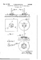
- Fig. 1 illustrates aside elevation, and Fig. 2, a plan of one embodiment; Fig. 3,-a side elevation, and Fig. 4, a plan of a modification; Fig. 5, a side elevation, and
- Fig. 7 a side elevation of the intermediate members employed in Figs. 5 and 6, and
- Fig. 8 a plan of these intermediate members on an enlarged scale.
- the contacting edges d of the individual anode plates (1 radiate from a center 0 in the manner of the rays of a star.
- the contact pillar or'post f designed as tripod, by means of small contact knife edges g, preferably in such a manner that the extension of its axis passes through the center 6.
- the contact pillar 7 may consist of a less precious metal, such as copper, if the level of the liquid is so chosen, that it is flush with the upper edge of the intermediate member 25. In this way the stock of silver of such a plantis considerably diminished and a very uniform distribution of the current is attained over the individual anode plates.
- the cathode located underneath the anode plates a is indicated atvh.
- a ring 2' is provided as interme iate member.
- This ring carries on its upper face three contact knife edges is and rests with its lower broadened face on three contact knife edges p cast or fixed on the anode plates (1.
- the anode plates are in this embodiment so arranged thatthey form a complete circle.
- the contact pillar or stem 7 consists in this embodiment likewise of a less precious metal, such as copper.
- the ring 11 may be constructed either of the preciousmetal to be refined or of a less precious metal coated with a pre cious metal.
- a copper ring may, for instance, first be coated with silver andthen with gold. This has the advantage that the ring i need be provided once only and that thus the stock of silver of the plant is still further reduced.
- a dish or bowl may be provided into which the contact pillar f is placed by means of three knife edges.
- FIGs. 5 and 6 it will be observed that three separate intermediate pieces m are provided in this embodiment of our invention, which by means of pins Z are inserted into holes provided in each anode plate a.
- These separate intermediate pieces m are themselves designed in the manner of small pillars or posts. Besides the pins Z they carry at their lower faces three contact spikes or contact knifeedges by means of which they rest upon projections 71. of the anodes a. At the top they are provided with Figures 3 and 4. Ifdesired, the knife edges 79 in the embodiment shown in Figs. 3 and 4 may be constructed similar to the intermediate pieces m of Figs. 5-8. vThe arrangement according to the Figs. 5 and 6 has the advantage that the points of contact of the intermediate members cannot slide on the anode plates, since the intermediate pieces are firmly held in position by the pins.
- anode plates might equally well consist of less or more pieces than the three shown throughout the drawings, forinstance of four squares or rectangles, each provided with a projection. Upon these projections would then be placed one or more intermediate members, for instance plates designed in the manner illustrated in Figs. 1 and 2, and upon these the contact pillar or stem constructed as tripod. Such an embodiment of our invention is, however, less favorable as regards the supply of current than the preferred constructions illustrated in the drawings.
- a plurality of anode plates located adjacent to each other in a common horizontal plane and adapted to be supported within an electrolytic tank, a'contact pillar of base metal for conducting the electric current to said plates, and one or more intermediate members havin a surface of noble metal and provided with tapered projections for positioning said members between said contact pillar and said plates in spaced relation thereto.
- a central contact pillar of base metal for leading in the electric current said pillar being in the form of a tripod, three rest upon each of said plates at at least one point.
- a central contact pillar of base metal for leading in the electric current said pillar being in the form of a tripod, three sector-like cast anode plates so disposed that their contacting edges radiate from a central point, a member intermediate said pillar and the anode plates and consisting at least in part of the precious metal to be refined, and a contact member between each of said plates and said intermediate member.
- a central contact pillar of base metal for leading in the electric current said pillar being in the form of a tripod, three secmetal for leading in the electric current, said pillar being in the form of a tripod, three sector-like cast anode plates so disposed that their contacting edges radiate from a central point, small pillars intermediate said central contact pillar and the anode plates and consisting at least in part of the precious metal to be refined, pins on said small pillars fitting holes in said anode plates, three projections on the lower face for contacting with the anode plates and a single projection on the upper face of said small pillars for establislr ing contact with said central contact pillar.
- a central contact pillar of base metal for leading in the electric current and members intermediate said pillar and the anode plates and consisting at least in part of the precious metal to be refined and adapted to distribute the'current equally over the individual anode plates, said intermediate members consisting of copper coated first with silver and then with gold.
Landscapes
- Chemical & Material Sciences (AREA)
- Engineering & Computer Science (AREA)
- Chemical Kinetics & Catalysis (AREA)
- Electrochemistry (AREA)
- Materials Engineering (AREA)
- Metallurgy (AREA)
- Organic Chemistry (AREA)
- Electrolytic Production Of Metals (AREA)
Description
M y 1932- v. EN'GELHARDT ET AL 1,357,590
APPARATUS FOR ELECTROLYTICALLY REFINING PRECIOUS METALS Filed May 3, 1929 muz|| INVE-MTQRS GEORQ 22241:)?
BY Jfan as n7- Jfz- (If ATTORME-VTE,
Patented May 10, 1932 UNITED s'rAgras PATENT OFFICE" VICTOR ENGELHARDT, GEORG EG-ER, AND HERBERT HEIN OF BERLIN-CHARIIOTTEN BURG, GERMANYpASSIGNORS TO SIEMENS & HALSKE, AKTIENGESELLSC'HAIT, OF SIEMENSSTADT, NEAR BERLIN, GERMANY, A CORPORATION OF GERMANYI APPARATUS FOR ELECTROLYTICALLY REFINING PRECIOUS METALS Application filed Kay 8, 1929, Serial No.
States patent to Balbach No. 588,524) the anodes are located horizontally in a box or vat with a perforated bottom constructed of wood, for instance. Between the anode plates and the bottom of the box there is inserted a filter cloth. While the process is being carried on the silver of the anodes which has passed into solution is deposited on the cathode, usually consisting of graphite, lo-
cated below the bottom of the box in the electrolyzer proper'whence it is removed peria plurality of contact pillars, posts or rods,
which consist of the raw silver to be refined or of fine silver.
A disadvantage of this rocess lies in the fact that the current is rat er unequally distributed over the individual anode plates. The stock of silver required for carrying out this recess is, furthermore, bound to be very considerable, since the contact pillar as well as any intermediate member placed between it and the anode-plates must consist of raw or fine silver and are thus exposed to the danger of becoming likewise dissolved during the process.
In the process described by Mobius, United States Patent No. 532,209, the material. to be refined isplaced upon plates formed as diaphragms. Metallic contact arms which at one end engage a current conductor rail and at their other ends rest on the material to be in the way of the operator.
360,072, and in Germany May 14, 1928.
the anodes. As the contact armsri idIy en gage the current conductor rail, it 6 ten happens that an arm remains suspended in its original position even after the metal below it has been dissolved away by electrolytic action, so that contact .between the arm and the mass of metal remains broken. A metallic arm can remain so suspended particularly when the surface of the conductor rails has become rough, which can scarcely be avoided in chemical operations.v
The object of our invention is to eliminate these drawbacks. According to our invention the contact pillar or .post is constructed of a non-precious metal and between it and the anode plates consisting of theprecious metalto be refined oneor a plurality of intermediate members is or are placed in such a manner that the passage of the current to the individual anode plates takes place uniformly. The anode plates may, furthermore, be cast in the form of sectors and be so arranged in relation to one another that their contacting edges extend radially from a center in the manner of the rays of a star. A contact pillar or post consisting of copper, for instance, and the intermediate members are then arranged in such a manner, that they are supported upon the three anode plates at three points or places designed as spikes or'knife edges, one for each anode plate. As intermediate member a disc, dish or ring may be employed, or separate intermediate members in the form of short pillars may be provided for this purpose and be fitted into holes or recesses, one in each 1 anode plate.
Various embodiments of our invention are illustrated in the drawings aflixed hereto and forming part of our specification. In" the drawings. 1
Fig. 1 illustrates aside elevation, and Fig. 2, a plan of one embodiment; Fig. 3,-a side elevation, and Fig. 4, a plan of a modification; Fig. 5, a side elevation, and
' Fig. 6, a plan of a further modification;
Fig. 7, a side elevation of the intermediate members employed in Figs. 5 and 6, and
Fig. 8, a plan of these intermediate members on an enlarged scale.
Like parts are indicated by like letters of reference in the various figures of the drawm s.
Iteferring to Figs. 1 and 2 of the drawings it will be observed that on three sector-like anode plates at consisting of the precious metal there is mounted-an intermediate member b likewise consisting of the precious metal to be refined in such a manner, that it touches with one contact knife edge 0 each of the anode plates (1.
The contacting edges d of the individual anode plates (1 radiate from a center 0 in the manner of the rays of a star. Upon the intermediate member I) is placed the contact pillar or'post f designed as tripod, by means of small contact knife edges g, preferably in such a manner that the extension of its axis passes through the center 6. Inthis arrangement the contact pillar 7 may consist of a less precious metal, such as copper, if the level of the liquid is so chosen, that it is flush with the upper edge of the intermediate member 25. In this way the stock of silver of such a plantis considerably diminished and a very uniform distribution of the current is attained over the individual anode plates. The cathode located underneath the anode plates a is indicated atvh.
In the modification illustrated in Fi s. 3 and 4 a ring 2' is provided as interme iate member. This ring carries on its upper face three contact knife edges is and rests with its lower broadened face on three contact knife edges p cast or fixed on the anode plates (1. The anode plates are in this embodiment so arranged thatthey form a complete circle. The contact pillar or stem 7 consists in this embodiment likewise of a less precious metal, such as copper. The ring 11 may be constructed either of the preciousmetal to be refined or of a less precious metal coated with a pre cious metal. For the refining of silver a copper ring may, for instance, first be coated with silver andthen with gold. This has the advantage that the ring i need be provided once only and that thus the stock of silver of the plant is still further reduced. Instead of this ring a dish or bowl may be provided into which the contact pillar f is placed by means of three knife edges.
Referring to Figs. 5 and 6, it will be observed that three separate intermediate pieces m are provided in this embodiment of our invention, which by means of pins Z are inserted into holes provided in each anode plate a. These separate intermediate pieces m are themselves designed in the manner of small pillars or posts. Besides the pins Z they carry at their lower faces three contact spikes or contact knifeedges by means of which they rest upon projections 71. of the anodes a. At the top they are provided with Figures 3 and 4. Ifdesired, the knife edges 79 in the embodiment shown in Figs. 3 and 4 may be constructed similar to the intermediate pieces m of Figs. 5-8. vThe arrangement according to the Figs. 5 and 6 has the advantage that the points of contact of the intermediate members cannot slide on the anode plates, since the intermediate pieces are firmly held in position by the pins.
It will be readily understood that the anode plates might equally well consist of less or more pieces than the three shown throughout the drawings, forinstance of four squares or rectangles, each provided with a projection. Upon these projections would then be placed one or more intermediate members, for instance plates designed in the manner illustrated in Figs. 1 and 2, and upon these the contact pillar or stem constructed as tripod. Such an embodiment of our invention is, however, less favorable as regards the supply of current than the preferred constructions illustrated in the drawings.
Various modifications and changes may be made without departing from the spirit and the scope of the invention, and we desire, therefore, that only such limitations shall be placed thereon as are imposed by the prior art.
\Ve claim as our invention:
1.. In an'apparatusfor electrolytically retining precious metals, such as silver, in combination, a plurality of anode plates located adjacent to each other in a common horizontal plane and adapted to be supported within an electrolytic tank, a'contact pillar of base metal for conducting the electric current to said plates, and one or more intermediate members havin a surface of noble metal and provided with tapered projections for positioning said members between said contact pillar and said plates in spaced relation thereto.
2. In an apparatusfor electrolytically refining precious metals, such as silver, in combination, a central contact pillar of base metal for leading in the electric current, said pillar being in the form of a tripod, three rest upon each of said plates at at least one point.
3. In an apparatus for electrolytically refining precious metals, such as silver, in combination, a central contact pillar of base metal for leading in the electric current, said pillar being in the form of a tripod, three sector-like cast anode plates so disposed that their contacting edges radiate from a central point, a member intermediate said pillar and the anode plates and consisting at least in part of the precious metal to be refined, and a contact member between each of said plates and said intermediate member.
4. In an apparatus for electrolytically refining precious metals, such as silver, in combination, a central contact pillar of base metal for leading in the electric current, said pillar being in the form of a tripod, three secmetal for leading in the electric current, said pillar being in the form of a tripod, three sector-like cast anode plates so disposed that their contacting edges radiate from a central point, small pillars intermediate said central contact pillar and the anode plates and consisting at least in part of the precious metal to be refined, pins on said small pillars fitting holes in said anode plates, three projections on the lower face for contacting with the anode plates and a single projection on the upper face of said small pillars for establislr ing contact with said central contact pillar. 6. In an apparatus for electrolytically refining precious metals, such as silver, in combination, a central contact pillar of base metal for leading in the electric current, and members intermediate said pillar and the anode plates and consisting at least in part of the precious metal to be refined and adapted to distribute the'current equally over the individual anode plates, said intermediate members consisting of copper coated first with silver and then with gold.
7. The combination as set forth in claim 3, wherein said intermediate member is in th form of a ring.
tures.
VICTOR ENGELHARDT. GEORG EGER.
HERBERT HEIN.
In testimony whereof we aifix our signa-
Applications Claiming Priority (1)
| Application Number | Priority Date | Filing Date | Title |
|---|---|---|---|
| DE1857590X | 1928-05-14 |
Publications (1)
| Publication Number | Publication Date |
|---|---|
| US1857590A true US1857590A (en) | 1932-05-10 |
Family
ID=7746308
Family Applications (1)
| Application Number | Title | Priority Date | Filing Date |
|---|---|---|---|
| US360072A Expired - Lifetime US1857590A (en) | 1928-05-14 | 1929-05-03 | Apparatus for electrolytically refining precious metals |
Country Status (1)
| Country | Link |
|---|---|
| US (1) | US1857590A (en) |
Cited By (1)
| Publication number | Priority date | Publication date | Assignee | Title |
|---|---|---|---|---|
| US2959532A (en) * | 1955-12-30 | 1960-11-08 | Philips Corp | Apparatus and method for the electrodeposition of rare metals |
-
1929
- 1929-05-03 US US360072A patent/US1857590A/en not_active Expired - Lifetime
Cited By (1)
| Publication number | Priority date | Publication date | Assignee | Title |
|---|---|---|---|---|
| US2959532A (en) * | 1955-12-30 | 1960-11-08 | Philips Corp | Apparatus and method for the electrodeposition of rare metals |
Similar Documents
| Publication | Publication Date | Title |
|---|---|---|
| Hutin et al. | Experimental study of copper deposition in a fluidized bed electrode | |
| JPS58182823A (en) | Plating apparatus for semiconductor wafer | |
| ES8406571A1 (en) | A process of electroforming a metal product and electroformed metal product. | |
| US1857590A (en) | Apparatus for electrolytically refining precious metals | |
| US1872290A (en) | Corrugated or threaded anode | |
| US2563903A (en) | Electrolytic cell for the deposition of gold and/or silver from solutions | |
| SU795506A3 (en) | Electrolytic cell for metal extraction | |
| US1519572A (en) | Electroplating | |
| US1836066A (en) | Electroplating apparatus | |
| US1765706A (en) | Dual anode | |
| US3799861A (en) | Electrical contact for equipment used in the electrolytical production of metals,particularly copper | |
| US4039407A (en) | Method for electrolytic silver recovery | |
| GB275223A (en) | Improvements in or relating to the electrical depositing of chromium | |
| US1521592A (en) | Eleotboplathtg apparatus | |
| US2946734A (en) | Contact element for electrolytic processing of wire and the like | |
| US2265645A (en) | Electrolytic cell | |
| US1030490A (en) | Apparatus for the recovery of precious metals. | |
| US3379631A (en) | Electrolytic apparatus | |
| US1427876A (en) | Apparatus for electrical etching | |
| US4000056A (en) | Apparatus for electrolytic metal recovery | |
| JP2015509558A (en) | Operation method of anode and electrolytic cell | |
| US2850448A (en) | Apparatus for electrolytically pointing wire | |
| US1837193A (en) | Method of electrodepositing precious metals and apparatus for practicing the same | |
| RU2094533C1 (en) | Cathode for copper electrolyzing by baseless technology | |
| US460354A (en) | von siemens |