US1857587A - Method for use in factory management - Google Patents
Method for use in factory management Download PDFInfo
- Publication number
- US1857587A US1857587A US327918A US32791828A US1857587A US 1857587 A US1857587 A US 1857587A US 327918 A US327918 A US 327918A US 32791828 A US32791828 A US 32791828A US 1857587 A US1857587 A US 1857587A
- Authority
- US
- United States
- Prior art keywords
- speed
- per minute
- frames
- pictures
- operator
- Prior art date
- Legal status (The legal status is an assumption and is not a legal conclusion. Google has not performed a legal analysis and makes no representation as to the accuracy of the status listed.)
- Expired - Lifetime
Links
- 238000000034 method Methods 0.000 title description 46
- 238000004519 manufacturing process Methods 0.000 description 6
- 239000006059 cover glass Substances 0.000 description 4
- 230000000694 effects Effects 0.000 description 2
- 238000012935 Averaging Methods 0.000 description 1
- 210000001217 buttock Anatomy 0.000 description 1
- 230000001747 exhibiting effect Effects 0.000 description 1
- 230000014509 gene expression Effects 0.000 description 1
Images


Classifications
-
- G—PHYSICS
- G03—PHOTOGRAPHY; CINEMATOGRAPHY; ANALOGOUS TECHNIQUES USING WAVES OTHER THAN OPTICAL WAVES; ELECTROGRAPHY; HOLOGRAPHY
- G03B—APPARATUS OR ARRANGEMENTS FOR TAKING PHOTOGRAPHS OR FOR PROJECTING OR VIEWING THEM; APPARATUS OR ARRANGEMENTS EMPLOYING ANALOGOUS TECHNIQUES USING WAVES OTHER THAN OPTICAL WAVES; ACCESSORIES THEREFOR
- G03B15/00—Special procedures for taking photographs; Apparatus therefor
- G03B15/08—Trick photography
Definitions
- the present invention relates to the use of photography to improve methods of manufacturing and to facilitate time study in conncction with manufacturing operations.
- the present method is applicable for setting a standard of effort in a wage incentive system.
- Figs. 1 to 8 inclusive show one form of projector with associated tachometer and indicating'equipment suitable for carrying out the method of this in ventlon.
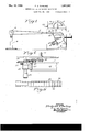
- Fig. 1 is a diagrammatic showing of a projector with a mechanical tachometer and indicating equipment
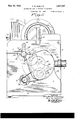
- F-ig. 2 is an enlarged side View of a projector and the associatedtachometer and indicating equipment
- Fig. 3 is a rear view while Fig. 4 is a showing of the other side view of this same equipment
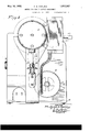
- Fig. 5 is a c tail.
- Fig. 7 shows a. form of dial for a drum-type tachometer
- Fig. 8 shows a modified form of disc-shaped dial
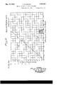
- Fig. 9 is a chart used in connection with the steps of the present method.
- a motion picture camera operating at a fixed speed preferably 1000 frames or pictures per minute is used to obtain a photographic record showin the machine or workman repeating the cycle of operations ofthe process to be studied.
- the photographic record when thus obtained may be formed into a loop which is projected at any desired speed, usually slower than that at which the picture was taken, in order to depict the record on a screen.
- the time study analyst can select from the p oto graphic record the portion thereof showing the process in a selected cycle of operations, each element of which is considered as perfect.
- the portion of the photographic record showing the perfect cycle of operations is then removed from the remainder of the photographic record and formed into a loop which may be projected by means of any suitable projector as a continuous repetition of the perfect cycle of operations.
- the time study analyst may time each element of the process by counting the number of pictures or frames necessary to depict the element of the process on the screen. Since it is assumed that the photographic record was made at a speed of 1000 frames per minute, this number of frames or pictures gives the thousandths (.001) part of a minute necessary to perform the operation. It will be understood that the photographic record may be taken at other. speeds than 1000 pictures per minute but in such case a different factor than .001 is necessary in obtaining the proper interval of time that has transpired. hile the analyst may actually count the number I of pictures necessary to depict any element of the process, equipment in the form of a mechanical counter is provided for this purpose in connection with the projector used.
- this loop may be emloyed in accordance with the present method in obtaining a-proper standard of effort in a wage incentive system.
- While wage incentive systems employ dif ferent methods of classifying productive effort or working speed of the operator studied, all methods of classification or rat-' ing may be reduced to expressions which state the working speed as a percentage above or below a standard speed which has been orbitrarily-adopted.
- the workmen are rated in -Bs per hour in which B is the unitof productive effort or work that can be performed by an average workman per unit of time after cerdelay and a rest period, have been added.
- This method is also very useful in case of a dispute as to the correctness of a given standard for the speed at which an operator must work in order-to meet the standard required of him may be duplicated on the screen for observation and may be compared with photographic records representing similar lines of production.
- FIG. 1 includes a projector generally designated 1 arranged to project a motion picture recorded in the form of a continuone loop of film 2 passing through the projector and over a pulley 3 mounted on an adjustable support or stand 4 so that the film can be continuously projected.
- a tachometer 5 either of the viscous drag type or of the magnetic type which is arranged to be driven from the shaft that actuates the shut ter of the projector so that the reading on the tachometer 5 indicates the number of frames or pictures per minute passing through the projector.
- the )rojector 1 includes with a vertical fiauge 7 mounted thereon to carry a tubular lens or objective mounting 8 and suitable focusing means therefor.
- the base 6 there is also mounted a motor 9 having a shaft 10 which in turn carries a a base pulley 11.
- a belt 12 passing over this pulley drives a second pulley 13 mounted in 00111 mon on a shaft with a gear 14 shown in dotted lines in Fig. 2.
- the gear 14 through a train of gears 15, 16, 17 18 and 19 drives sprocket 20.
- This sprocket pulls the loop of film 2 behind the idlers 21 around the guide surface 22 so that the frames 23 of the film may be successively positioned before the traming gate 2 1 to projectv the pictures through the objective. It will he noted in Fig.
- This tachometer may be of any one of several well-known types such as the viscous drag type or of the magnetic type and is provided with a dial 4.0 which may be either or the drum type as shown in Fig.7 or of the disc type as shown in Fig. 8.
- the lower margin of the dial 40 of Fig. 7 is graduated in frames per minute reading from 500 to 2000, while the periphery of the dial of Fig. 8 has a portion thereof similarly graduated in frames per minute reading from 500 to 2000.
- the projection speed of 1000 frames per minute, which is the preferable speed to operate the projector is indicated by avertical line 42.
- the dial of Fig. 7 is provided with aseries of curved lines one of which is designated 41.
- each of these lines has a special designation such as; 40, 50, 60 115, 120, reading in Bs per hour, that is, units of work.
- c' such as 41 are shown in Fig. 8 but in this instance the lines are shown in the form 0i spirals.
- the dial 40 either in the form shown in Fig. 7 or that shown in Fig. '8 is mounted to operate behind a window in a cover glass havii inc graduations such as 43 etched thereon. The numerals adjacent these graduations are also in Bs per hour but these graduations and line 11 may be in any other units of work per unit of time.
- the dial of Fig. 8 is not drawn to scale with respect to the graduations 43 on the cover glass, but these graduations may be spaced to coincide with the space between the spiral lines such as E1 at the point on the imilar lines dial opposite the 1000 graduation in the frames per minute scale.
- the dial in order to indicate projection speeds and the speed classification or rating of the operator on the screen, which rating ma be in percentages of the standard or may be in Bs per hour if the classification of the Bedaux system is used, has a variable deflection scale.
- the need for such a variable scale will be seen from the following illustration: Assume the Bedaux system is used. ,A pic: ture is taken at the rate of 1000 frames per minute of an operator whose speed is rated at Bs per hour. Increase in projection speed to 1250 frames per minute gives an apparent increase of activity on the screen of 25%. Hence, the apparent speed of the operator is raised to Bs per hour.
- the deflection reading must be 15 Bs per hour divided by 250 frames per minute, or .06 Bs per hour per frame per minute.
- the same increase in projection speed (1000 to 1250 frames per minute) when applied to a picture of an operator exhibiting Bs per hour will increase the apparent speed from 80 to 100 B's er hour.
- the deflection reading must, thereore, be 20 Bs per hour divided by 250 frames per minute, or .08 Bs per hour per frame er minute.
- the dial is in effeet a calculating device which calculates the result of dividing the speed of the worker as originally photographed b 1000 and multiplying the quotient by the rames per minute to give the result as the apparent speed of the Worker as seen on the screen, that is, the dial calculates, the following formula:
- a mechanical counter 50 which may be of the type known in the art as a Veeder counter. This counter is driven through a pair of gears 51 which are actuated at the same speed as .the shutter so that it counts each picture projected.
- a rheostat 31 is carried by the frame of the tachometer 5.
- the adjustable member 33 of this rheostat permits adjustment of the motor speed and therefore the speed of projection so that if it is desired to project 1000 frames or pictures per minute this member is moved until the dial of the tachometer indicates 1000 frames per minute.
- Other settings of the rheostat will effect other projection speeds and corresponding readings of projection speeds in the tachometer.
- the method of timing an element of a. cycle of movements which comprises taking a series of photographs representing a true motion picture of said element taken at a uniform predetermined spee'd, counting the number of pictures necessary to portray the element of thecycle timed, and calculating the elapsed time from the number of pietures counted in conjunction with the uniform )redetermined speed at which said series o photogra hs were taken.
- the met-ho of timing an element of a cycle of movements which comprises obtaining a series of photographs representing a true motion picture of said element taken at a uniform predetermined speed, rojecting a d pictures at said predetermined speed to Put a motion picture, countin the num- .-J 1 of pictures that are projected to represent the element of the cycle timed,and multiplying the number of these pictures thus counted by the time interval that elapsed for the exposure and movement of the photographs when they were taken.
- the method of timing an element or process which comprises photographing the process at a fixed predetermined: speed to obtain a true motion picture record thereof, projecting said motion picture record, counting the number of pictures necessary to portray said element, and calculating the time interval from the number of pictures i.
- the method of obtaining the classificycle of operations under consideration projecting the photogra hic record at a known projection speed an estimating the speed of the operator performing the cycle of oper- 5 ations at the known projection speed as compared to the speed of a standard operator.
- the method of obtaining the classification for the effective effort or working speed of an operator which comprises obtaining a motion picture record at anniform speed of an operator performing the cycle of operations under consideration, projecting the hotographic record at various known spee s and estimating the speed of the operator performing the cycle of operations at each projection speed as compared to the speed of a standard operator.
- the method of obtaining the classification for the effective effort or working speed of an operator which comprises obtaining a motion picture record at a uniform speed of an operator performing the cycle of operations under consideration, projecting the photographic record at Various known speeds, estimating the speed of the operator performing the cycle of operations at each projection speed as compared to the speed of a standard operatorand averaging the estimates of the speed of the operator at the various projection speeds.
Landscapes
- Physics & Mathematics (AREA)
- General Physics & Mathematics (AREA)
- Length Measuring Devices By Optical Means (AREA)
Description
May 10, 1932. F, E, D 1,857,587
METHOD FOR USE IN FACTORY MANAGEMENT Filed Dec. 22, 1928 6 Sheets-Sheet 1 u n u c 1 n n 3 I: u u a l ATTORNEY-S.
y 2- F. E. DARLING 1,857,587
METHOD FOR USE IN FACTORY MANAGEMENT Filed Dec. 22 1928 6-Sheets-Sheet 2 ATTO'RNEYS.
y 1932- F. E. DARLING 1,357,587
METHOD FOR USE IN FACTORY MANAGEMENT Filed Dec. 22, 1928 6 Sheets-Sheet 3 Y Q JZ HHHIHHHHHHHIHHHIHHIHHHHHY Hill!MHHHHIHHHH HHIHHHHHHHHHHHH I. (a
\ y 1719 K u 30 If; -16 9; I 1
iii. -1
, INVENTOR fag/6nd zV/Qr i ATTORNEYS,
May 10, 1932. 'F. E DARLING I 1,857,587
METHOD FOR USE IN FACTORY MANAGEMENT Filed Dec. 22 1928 6 Sheets-Sheet 4 ATTdRNEYs.
May 10, 1932. F. E. DARLING 7, 8
METHOD FOR USE IN FACTORY MANAGEMENT Filed Dec. 22, 1928 6 Sheets-Sheet 5 ATTORN EYS.
May 10, 1932. F. E. DARLING- METHOD FOR USE IN FACTORY MANAGEMENT Filed Dec. 22, 1928 6 Sheets-Sheet 6 sw k wm N W NWR g a :aa g 3 m w w w w m w fiea en gzwarzz fy BY 7% M ATTOIRNEYS.
QN PN EN Patented May 10, 1932 UNITED STATES PATENT OFFICE- FREDEBICK E. DARLING, ROCHFSTER, NEW YORK, ASSIGNOR T EASTMAN KODAK COMPANY, OF ROCHESTER, NEW YORK, A CORPORATION OF NEW YORK METHOD FOR USE IN FACTORY MANAGEMENT Application filed December 22, 1928. Serial No. 327,918.
The present invention relates to the use of photography to improve methods of manufacturing and to facilitate time study in conncction with manufacturing operations.
' In the past when it was desired to improve any manufacturing process it was customary for a trained analyst to observe a workman performing the steps of the process. The presence of such an analyst Was dism tracting to the workman and since his pay was usually affected by the result of the analysts study he frequently did not cooperate by putting forth his best effort in performing his work, while being observed. In
accordance with the present invention it is proposed to utilize a photographic record I taken at uniform speed, of the workman performing the operation or series of operations under consideration. It has previously been a proposed to utilize motion pictures for time study work but the have not gone into wide use owing to the act that proper methods of using them had not been developed and suitable apparatus for use therewith, had not been designed.
It has formerly been the practice in time study work to employ a stop watch for timing' the various elements of the cycle of operations, while the analyst observed a work man actually engaged in manufacturing and the result of these observations was then tabulated in a record book for reference. As
2 further step in the present method it is proposed to take-a motion picture record of the process under consideration by means of a motion picture camera operating at a fixed speed, such as 1000 frames or pictures per minute and then count the number of frames or pictures necessary to depict the clei'nent ofthe operation being studied. This number will then indicate the thousandths of a minute necessary to perform the operation It has been proposed to use motion r s in timing the different elements or ope of a process but it h s been c Cc.
as can be determined. actually pin the passage of time marked by a time measuring device in the foreground of the scene including the workman to be studied or else to incorporate in the camera a timing device which was photographed to mark the time interval that transpired during the photographing of the process. The photographing of the time measuring device in the foreground of the process photographed, has practically made this method useful only in the laboratory since in the factory it is difficult to obtain the proper light and to focus the camera both on the time measuring device and on the hands of the workman. The use of the time measuring device incor porated within the camera has not come into use since this arrangement is complicated due to the fact that it is necessary to employ clutch mechanism to connect the timing device with the shutter of the camera and there is a further objection that a portion of each frame or picture is obscured by the photograph thereon of the time measuring device.
In addition to discovering the best process of manufacturing and in addition to timing the various elements of the process under consideration, the present method is applicable for setting a standard of effort in a wage incentive system.
Other applications of this method will be readily understood from the following drawings when taken with the description and appended claims.
In the drawings Figs. 1 to 8 inclusive show one form of projector with associated tachometer and indicating'equipment suitable for carrying out the method of this in ventlon. (if these figures, Fig. 1 is a diagrammatic showing of a projector with a mechanical tachometer and indicating equipment; F-ig. 2 is an enlarged side View of a projector and the associatedtachometer and indicating equipment; Fig. 3 is a rear view while Fig. 4 is a showing of the other side view of this same equipment; Fig. 5 is a c tail. showing a portion of the mechanical r 5 A .ndvaiicing sprocket of the r; l 6 is a section of the loop of nun or other photographic record suitable for use in carrying out the present method in connection with equipment of the foregoing figures; Fig. 7 shows a. form of dial for a drum-type tachometer; while Fig. 8 shows a modified form of disc-shaped dial; and Fig. 9 is a chart used in connection with the steps of the present method.
In carrying out the method of the present invention a motion picture camera operating at a fixed speed preferably 1000 frames or pictures per minute is used to obtain a photographic record showin the machine or workman repeating the cycle of operations ofthe process to be studied. The photographic record when thus obtained may be formed into a loop which is projected at any desired speed, usually slower than that at which the picture was taken, in order to depict the record on a screen. In this wa the time study analyst can select from the p oto graphic record the portion thereof showing the process in a selected cycle of operations, each element of which is considered as perfect. The portion of the photographic record showing the perfect cycle of operations is then removed from the remainder of the photographic record and formed into a loop which may be projected by means of any suitable projector as a continuous repetition of the perfect cycle of operations. Having thus obtained the correct process the time study analyst may time each element of the process by counting the number of pictures or frames necessary to depict the element of the process on the screen. Since it is assumed that the photographic record was made at a speed of 1000 frames per minute, this number of frames or pictures gives the thousandths (.001) part of a minute necessary to perform the operation. It will be understood that the photographic record may be taken at other. speeds than 1000 pictures per minute but in such case a different factor than .001 is necessary in obtaining the proper interval of time that has transpired. hile the analyst may actually count the number I of pictures necessary to depict any element of the process, equipment in the form of a mechanical counter is provided for this purpose in connection with the projector used.
After obtaining the perfect process by means of the photographic record made in ,the form of a loop, this loop may be emloyed in accordance with the present method in obtaining a-proper standard of effort in a wage incentive system.
While wage incentive systems employ dif ferent methods of classifying productive effort or working speed of the operator studied, all methods of classification or rat-' ing may be reduced to expressions which state the working speed as a percentage above or below a standard speed which has been orbitrarily-adopted. In one wage incentive system which is known as the Bedaux system the workmen are rated in -Bs per hour in which B is the unitof productive effort or work that can be performed by an average workman per unit of time after cerdelay and a rest period, have been added.
Since the unit of time in this system is usu-' ally one minute, an average workman produces 60 Bs or units of work er hour and he is rated as a 60 B hour wor man. Even those systems which classify the working speed as poor, fair, good or excellent, must have established numerical ratios such that the relation of these different classifications one to the other may be expressed. It therefore becomes necessary for the trained time study man or analyst to recognize the various classes of speed so that a standard time may be determined by adding the proper percenta e to the time required b the workmen eing studied. It will .t us be seen that the classification required of the time study analyst is made by judgment and it is frequently found that a time study analyst, even though his judgment of certain speeds may be good, has a tendency to underestimate or overestimate certain other speeds. As an aid to the analysts judgment in recognizing certain speeds the present method of using motion pictures has been devised. A photographic record having a perfectly executed cycle of operations is formed into a loop and when placed in a projector may be projected as a continuous repetition of the cycle of operations. The time study analyst applies his judgment to the reading of the speed of the operator projected on the screen. This he does at several different projection speeds such as 600, 800, 900, etc., frames per minute and plots the points a, b, 0, etc, on a chart '(Fig. 9) using the projection speed, that is frames per minute and the analysts judgment of the speed of the operator either in Bs perhour or their equivalent percentage above or below standard (both shown at the left of this chart) as co-ordinates. A straight line L drawn through the origin and as nearly as possible through the average positions of the plotted points, averages out the inconsistencies of judgment and gives the time study analysts true judgment of any speed. Since the original picture was taken at a speed of 1000 frames per minute, the operators speed line Y, passing through the intersection of the leveling factor line L with the film speed line X, indicates how much the workman was above or below standard speed. In the example just referred to in Fig. 0 the operators speed was ten per cent above the standard so that it is necessary to add ten per cent to the time indicated by the number of frames or pictures in the loop in order to arrive at the standard time of the operation pictured. For operators speeds under the standard, that is 100%, a similar computation is made but in this instance it is necessary to subtract the percentage below standard from the time indicated by the number of frames.
means? Having thus obtained the chart (Fig. 9) showing the correct rating line L as determined by an experienced observer or analyst, it is possible to show a student or novice any degree of workmans speed through the use the chart by first finding the correct projection speed that must be employed to represent the desired degree of speed of the workman represented. For example it is ossible to show a 100% speed (60 Bs in the edaux system) by noting the intersection of the 100% line with the rating line L which indicates that the correct projection speed in this case is 900 frames per minute. This methodis also very useful in case of a dispute as to the correctness of a given standard for the speed at which an operator must work in order-to meet the standard required of him may be duplicated on the screen for observation and may be compared with photographic records representing similar lines of production.
W'hile it will be understood that the present method can be put into practice by the use of any well-known projector provided with a frame or picture counter and any suitable deflection constant tachometer provided with two scales one graduated in frames or pictures per minute and the other scale indi cating the speed classification of the operator projected on the screen, a convenient type of this equipment is shown in Figs. 1 to 8 in which the tachometer may be either of the magnetic type or of the viscous drag type. This method may also be put into practice by means of the projector and electrical tachometer equipment disclosed in the co-pending application of Lawrence T. Littlefield. Serial No. 327,917, filed December 22, 1928.
By reference to Figs. 1 to 9 a more complete understanding of the apparatus for performing the method of this invention, will be had especially as to the manner in which it is used in connection with the above described method. The diagrammatic showing of Fig. 1 includes a projector generally designated 1 arranged to project a motion picture recorded in the form of a continuone loop of film 2 passing through the projector and over a pulley 3 mounted on an adjustable support or stand 4 so that the film can be continuously projected. There is mechanically mounted on the projector a tachometer 5 either of the viscous drag type or of the magnetic type which is arranged to be driven from the shaft that actuates the shut ter of the projector so that the reading on the tachometer 5 indicates the number of frames or pictures per minute passing through the projector. The )rojector 1 includes with a vertical fiauge 7 mounted thereon to carry a tubular lens or objective mounting 8 and suitable focusing means therefor. On
the base 6 there is also mounted a motor 9 having a shaft 10 which in turn carries a a base pulley 11. A belt 12 passing over this pulley drives a second pulley 13 mounted in 00111 mon on a shaft with a gear 14 shown in dotted lines in Fig. 2. The gear 14 through a train of gears 15, 16, 17 18 and 19 drives sprocket 20. This sprocket pulls the loop of film 2 behind the idlers 21 around the guide surface 22 so that the frames 23 of the film may be successively positioned before the traming gate 2 1 to projectv the pictures through the objective. It will he noted in Fig. 2 that the gear 15 has an arm 25 pivoted thereto while the gear 14 has pivoted thereto a link 26 which in turn is pivoted to the arm 25. It is unnecessary to describe the action of this arm and link since they are well-known in commercial devices but it is sufiicient to state that the free end of the arm 25 engages a pair of openings such as 32 in the film to pull it one frame at a time into projecting )osition. It Willbe noted that the shaft caring the sprocket 20 has a crank 26 by which the film may be moved at will by the operator. From the showing in Figs. 3 and 4 it will be seen that the shaft 27 on which the gear 16 is mounted, transmits its motion through a pair of miter gears 28to a vertical shaft 29 which drives the mechanical tachometer 5.
This tachometer may be of any one of several well-known types such as the viscous drag type or of the magnetic type and is provided with a dial 4.0 which may be either or the drum type as shown in Fig.7 or of the disc type as shown in Fig. 8. The lower margin of the dial 40 of Fig. 7 is graduated in frames per minute reading from 500 to 2000, while the periphery of the dial of Fig. 8 has a portion thereof similarly graduated in frames per minute reading from 500 to 2000. For convenience in reading the scale of 7 the projection speed of 1000 frames per minute, which is the preferable speed to operate the projector, is indicated by avertical line 42. The dial of Fig. 7 is provided with aseries of curved lines one of which is designated 41. It will be noted that each of these lines has a special designation such as; 40, 50, 60 115, 120, reading in Bs per hour, that is, units of work. c' such as 41 are shown in Fig. 8 but in this instance the lines are shown in the form 0i spirals. The dial 40 either in the form shown in Fig. 7 or that shown in Fig. '8 is mounted to operate behind a window in a cover glass havii inc graduations such as 43 etched thereon. The numerals adjacent these graduations are also in Bs per hour but these graduations and line 11 may be in any other units of work per unit of time. It should be pointed out that the dial of Fig. 8 is not drawn to scale with respect to the graduations 43 on the cover glass, but these graduations may be spaced to coincide with the space between the spiral lines such as E1 at the point on the imilar lines dial opposite the 1000 graduation in the frames per minute scale.
The dial in order to indicate projection speeds and the speed classification or rating of the operator on the screen, which rating ma be in percentages of the standard or may be in Bs per hour if the classification of the Bedaux system is used, has a variable deflection scale. The need for such a variable scale will be seen from the following illustration: Assume the Bedaux system is used. ,A pic: ture is taken at the rate of 1000 frames per minute of an operator whose speed is rated at Bs per hour. Increase in projection speed to 1250 frames per minute gives an apparent increase of activity on the screen of 25%. Hence, the apparent speed of the operator is raised to Bs per hour. To indicate this change the deflection reading must be 15 Bs per hour divided by 250 frames per minute, or .06 Bs per hour per frame per minute. However, the same increase in projection speed (1000 to 1250 frames per minute) when applied to a picture of an operator exhibiting Bs per hour will increase the apparent speed from 80 to 100 B's er hour. The deflection reading must, thereore, be 20 Bs per hour divided by 250 frames per minute, or .08 Bs per hour per frame er minute. Such a tachometer elimi nates tie need for a chart for determining the speed of an operator for a given projection s eed.
Itwili thus be seen that the dial is in effeet a calculating device which calculates the result of dividing the speed of the worker as originally photographed b 1000 and multiplying the quotient by the rames per minute to give the result as the apparent speed of the Worker as seen on the screen, that is, the dial calculates, the following formula:
Where Swspeed of worker when photographed s=apparent speed of the Worker on the screen F=film speed or frames per minute when the picture was taken f=film speed or frames per minute as projected. In using this apparatus to indicate any desired speed classification suchas 60 HS per hour of a workman who was working at the rate of 60 Bs per hour when photographed, the speed of the projector is varied until the 60 B line designated 41 coincides with the 60 B mark on graduations 4 on the cover glass. This indicates that the picture represents a Workman working at the speed of 60 Bs per hour. If it is now desired to represent the same workman operating at the 5 rate of 80 Bs per hour, the speed of projection is increased until the 80 B graduation line on the dial 40 coincides with the graduation mark 60 B on the graduations 43 of the cover glass.
In order to simplify the step of counting the number of frames projected for the urpose of timing any element or elements 0 the cycle of operations studied a mechanical counter 50 is provided which may be of the type known in the art as a Veeder counter. This counter is driven through a pair of gears 51 which are actuated at the same speed as .the shutter so that it counts each picture projected.
For convenience in varying the speeds in the motor 9 a rheostat 31 is carried by the frame of the tachometer 5. The adjustable member 33 of this rheostat permits adjustment of the motor speed and therefore the speed of projection so that if it is desired to project 1000 frames or pictures per minute this member is moved until the dial of the tachometer indicates 1000 frames per minute. Other settings of the rheostat will effect other projection speeds and corresponding readings of projection speeds in the tachometer.
I claim as my invention:
1. The method of timing an element of a. cycle of movements which comprises taking a series of photographs representing a true motion picture of said element taken at a uniform predetermined spee'd, counting the number of pictures necessary to portray the element of thecycle timed, and calculating the elapsed time from the number of pietures counted in conjunction with the uniform )redetermined speed at which said series o photogra hs were taken.
v2. The met-ho of timing an element of a cycle of movements which comprises obtaining a series of photographs representing a true motion picture of said element taken at a uniform predetermined speed, rojecting a d pictures at said predetermined speed to Put a motion picture, countin the num- .-J 1 of pictures that are projected to represent the element of the cycle timed,and multiplying the number of these pictures thus counted by the time interval that elapsed for the exposure and movement of the photographs when they were taken.
3. The method of timing an element or process which comprises photographing the process at a fixed predetermined: speed to obtain a true motion picture record thereof, projecting said motion picture record, counting the number of pictures necessary to portray said element, and calculating the time interval from the number of pictures i. The method of obtaining the classificycle of operations under consideration, projecting the photogra hic record at a known projection speed an estimating the speed of the operator performing the cycle of oper- 5 ations at the known projection speed as compared to the speed of a standard operator.
5. The method of obtaining the classification for the effective effort or working speed of an operator which comprises obtaining a motion picture record at anniform speed of an operator performing the cycle of operations under consideration, projecting the hotographic record at various known spee s and estimating the speed of the operator performing the cycle of operations at each projection speed as compared to the speed of a standard operator.
6. The method of obtaining the classification for the effective effort or working speed of an operator which comprises obtaining a motion picture record at a uniform speed of an operator performing the cycle of operations under consideration, projecting the photographic record at Various known speeds, estimating the speed of the operator performing the cycle of operations at each projection speed as compared to the speed of a standard operatorand averaging the estimates of the speed of the operator at the various projection speeds.
Signed at Rochester, New York, this 18th day of December, 1928. I
FREDERICK E. DARLING.
Priority Applications (1)
| Application Number | Priority Date | Filing Date | Title |
|---|---|---|---|
| US327918A US1857587A (en) | 1928-12-22 | 1928-12-22 | Method for use in factory management |
Applications Claiming Priority (1)
| Application Number | Priority Date | Filing Date | Title |
|---|---|---|---|
| US327918A US1857587A (en) | 1928-12-22 | 1928-12-22 | Method for use in factory management |
Publications (1)
| Publication Number | Publication Date |
|---|---|
| US1857587A true US1857587A (en) | 1932-05-10 |
Family
ID=23278647
Family Applications (1)
| Application Number | Title | Priority Date | Filing Date |
|---|---|---|---|
| US327918A Expired - Lifetime US1857587A (en) | 1928-12-22 | 1928-12-22 | Method for use in factory management |
Country Status (1)
| Country | Link |
|---|---|
| US (1) | US1857587A (en) |
Cited By (2)
| Publication number | Priority date | Publication date | Assignee | Title |
|---|---|---|---|---|
| US2603887A (en) * | 1947-11-01 | 1952-07-22 | Jr Phil Carroll | Time study training apparatus |
| US2917834A (en) * | 1957-06-17 | 1959-12-22 | Western Electric Co | Method of preparing and presenting assembling instructions by pictorial representations |
-
1928
- 1928-12-22 US US327918A patent/US1857587A/en not_active Expired - Lifetime
Cited By (2)
| Publication number | Priority date | Publication date | Assignee | Title |
|---|---|---|---|---|
| US2603887A (en) * | 1947-11-01 | 1952-07-22 | Jr Phil Carroll | Time study training apparatus |
| US2917834A (en) * | 1957-06-17 | 1959-12-22 | Western Electric Co | Method of preparing and presenting assembling instructions by pictorial representations |
Similar Documents
| Publication | Publication Date | Title |
|---|---|---|
| US2209156A (en) | Photographic camera | |
| US1857587A (en) | Method for use in factory management | |
| US2663217A (en) | Method for determining the velocity and acceleration characteristics of moving objects | |
| US2352176A (en) | Photographic arrangement | |
| US2247323A (en) | Photographic exposure apparatus | |
| US2114024A (en) | Speed determination | |
| US1907549A (en) | Method of measuring speeds photographically | |
| US2813469A (en) | Photographic camera | |
| US2229289A (en) | Photographic camera | |
| US2382617A (en) | Method of photographically recording the order of passage of moving objects | |
| US1980217A (en) | Light gauging apparatus | |
| US2203209A (en) | Exposure meter | |
| US1857204A (en) | Apparatus for use in factory management | |
| US2779017A (en) | Apparatus and method for indicating the position and motion of phenomena in space | |
| US2659264A (en) | Method of determining the velocity and acceleration characteristics of moving objects | |
| US2484735A (en) | Extinction type exposure meter with automatic eye sensitivity compensation | |
| GB1058575A (en) | Improvements in and relating to photographic and cinematographic cameras | |
| US1898179A (en) | Aerial photography | |
| USRE22881E (en) | Method of photographically re | |
| US2321420A (en) | Exposure determining device | |
| US1032867A (en) | Film-camera. | |
| US2358323A (en) | Camera | |
| US1788655A (en) | Means for adjusting stop aperture of cameras relatively to distance | |
| US3182400A (en) | Device and method for measuring the surface velocity of moving water | |
| US1809599A (en) | Talking cartoon motion picture |