US1857577A - Transformer - Google Patents
Transformer Download PDFInfo
- Publication number
- US1857577A US1857577A US401247A US40124729A US1857577A US 1857577 A US1857577 A US 1857577A US 401247 A US401247 A US 401247A US 40124729 A US40124729 A US 40124729A US 1857577 A US1857577 A US 1857577A
- Authority
- US
- United States
- Prior art keywords
- transformer
- voltage
- primary
- resistance
- coil
- Prior art date
- Legal status (The legal status is an assumption and is not a legal conclusion. Google has not performed a legal analysis and makes no representation as to the accuracy of the status listed.)
- Expired - Lifetime
Links
- 238000004804 winding Methods 0.000 description 7
- 238000010079 rubber tapping Methods 0.000 description 3
- 235000007119 Ananas comosus Nutrition 0.000 description 1
- 244000099147 Ananas comosus Species 0.000 description 1
- 101100001674 Emericella variicolor andI gene Proteins 0.000 description 1
- 230000004075 alteration Effects 0.000 description 1
- 238000009795 derivation Methods 0.000 description 1
- 238000009434 installation Methods 0.000 description 1
- VLKZOEOYAKHREP-UHFFFAOYSA-N n-Hexane Chemical compound CCCCCC VLKZOEOYAKHREP-UHFFFAOYSA-N 0.000 description 1
Images
Classifications
-
- H—ELECTRICITY
- H01—ELECTRIC ELEMENTS
- H01F—MAGNETS; INDUCTANCES; TRANSFORMERS; SELECTION OF MATERIALS FOR THEIR MAGNETIC PROPERTIES
- H01F29/00—Variable transformers or inductances not covered by group H01F21/00
- H01F29/02—Variable transformers or inductances not covered by group H01F21/00 with tappings on coil or winding; with provision for rearrangement or interconnection of windings
- H01F29/025—Constructional details of transformers or reactors with tapping on coil or windings
Definitions
- This invention relates to transformers having a subdivided exciting coil, whereby they may be connected to networks of different voltages.
- An object of the invention is to provide an improved transformer adapted to be supplied with different voltages, the output voltage remaining unvaried when the primary connections are correctly made.
- Another object is to equalize the voltage drop in the transformer, irrespective as to which of the primary voltages for which the transformer is adapted, is applied.
- a transformer made in accordance with the invention may be used in combination with consuming apparatus for which a predetermined voltage is necessary, such for instance, as X-ray installations and the like, so as to enable the operation of the apparatus when the available source of alternating current has the wrong voltage. 4
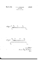
- Figure 1 shows the coil of an autotransformer.
- Figure 2 illustrates a transformer having separate primary and secondary coils.
- S and S designate terminals from which the secondary voltage is obtained.
- Primary connecting points are marked by P P P and P
- the transformer is adapted for three primary voltages, each exciting the same secondary voltage across terminals S1 and S
- One voltage may be applied between P and P another voltage between P and P and a third voltage between P and P
- the ratio of the turns comprised between P and P P and P P and R respectively is presumed to be such that in each case the secondary voltage obtained from S and S has the same value.
- the portions into which the transformer coil is subdivided have different ohmic resistances, on the understanding that the resistance per turn of the portion between P and P and that of the portion between P and P, are
- the potential drop may be rendered independent of the primary voltage, provided this be applied to the correct connecting points.
- the secondary voltage is obtained from terminals S and S. of the secondary winding; and the separate exciting coil, having terminals P and P and tappings P and P serves for the connection to different sources of current.
- the sections in which the primary coil is subdivided by the tappings P and P also have different resistances per unit of length.
- the alteration of the resistance may be ensured equally well by providing wires of the same material but of different diameter, as by providing wires of material having a different specific resistance.
- i means the secondary current, '93 the resistance of the secondary calm; the resistance of the primary coil and p is the ratio bftransformation, thus the quotient of the primary and secondary turns.
- a transformer having its exciting coil; ub r de ntos by' t east Qne apping; one section of said coil; being made off wireth sp cific re tane i' fl th: r at 'Q he ir const tut ng; an he sectionf A nsfa me aving t xeitingv oil; i de tq e pns y.
Landscapes
- Engineering & Computer Science (AREA)
- Power Engineering (AREA)
- Coils Or Transformers For Communication (AREA)
Description
y 1932- N. A. .1. VOORHOEVE 7, 77
TRANSFORMER Filed Oct. 21, 1929 WVWIS4 [vi/c rltbr 1 17147: Voorhoevz a Wag? %a( warm.
Patented May 10, 1932 UNITED STATES PATENT OFFICE NICOLAAS ANTHONY JOI-IANNES VOORHOEVE, OF EINDHOVEN, NETHERLANDS, A-
SIGNOR TO N. V. PHILIPS GLOEILAMIENFABRIEKEN, OF EINDHOVEN, NETHER- LANDS, A LIMITED LIABILITY COMPANY OF THE NETHERLANDS TRANSFORMER Application filed October 21, 1929, Serial No. 401,247, and in the Netherlands November s, 1923.
This invention relates to transformers having a subdivided exciting coil, whereby they may be connected to networks of different voltages.
An object of the invention is to provide an improved transformer adapted to be supplied with different voltages, the output voltage remaining unvaried when the primary connections are correctly made.
Another object is to equalize the voltage drop in the transformer, irrespective as to which of the primary voltages for which the transformer is adapted, is applied.
A transformer made in accordance with the invention may be used in combination with consuming apparatus for which a predetermined voltage is necessary, such for instance, as X-ray installations and the like, so as to enable the operation of the apparatus when the available source of alternating current has the wrong voltage. 4
The invention will be described with reference to the accompanying drawings, which comprises two schematic views showing embodiments of the invention.
Figure 1 shows the coil of an autotransformer.
Figure 2 illustrates a transformer having separate primary and secondary coils.
Referring to Figure 1, S and S designate terminals from which the secondary voltage is obtained. Primary connecting points are marked by P P P and P The transformer is adapted for three primary voltages, each exciting the same secondary voltage across terminals S1 and S One voltage may be applied between P and P another voltage between P and P and a third voltage between P and P The ratio of the turns comprised between P and P P and P P and R respectively is presumed to be such that in each case the secondary voltage obtained from S and S has the same value.
According to the invention the portions into which the transformer coil is subdivided have different ohmic resistances, on the understanding that the resistance per turn of the portion between P and P and that of the portion between P and P, are
greater than the resistance per turn of the portion between P and P and that the resistance per turn of the portion between P and and that of the portion between P and P also have a mutual difference.
If the winding of the transformer would have throughout its whole length the same resistance per turn, unequal potential drops will occur when the transformer is connected to different primary voltages. This voltage drop is the difference between the secondary voltage when the transformer is unloaded and that which occurs when the secondary circuit is closed. This potential drop of course depends on the load current, but also depends on the resistance in the transformer windings. As a consequence thereof different primary voltages, so applied to the transformer that the secondary voltage at no-load remains unvaried, will produce difierent secondary voltages when the transformer is loaded, even if the secondary current is kept unvaried. The smaller the primary voltage, the greater the potential drop will be.
Making the parts of the winding corresponding to smaller voltages, of a wire having a smaller resistance per unit of length will cause the ohmic potential drop to decrease in the case of smaller voltages. hen
the proportions are properly chosen the potential drop may be rendered independent of the primary voltage, provided this be applied to the correct connecting points.
In Figure 2 the secondary voltage is obtained from terminals S and S. of the secondary winding; and the separate exciting coil, having terminals P and P and tappings P and P serves for the connection to different sources of current.
The sections in which the primary coil is subdivided by the tappings P and P also have different resistances per unit of length.
The alteration of the resistance may be ensured equally well by providing wires of the same material but of different diameter, as by providing wires of material having a different specific resistance.
It will be obvious to one skilled in the art how the proportions of the resistances of the various sections can be ascertained, the necessary derivations for this purpose not exceeding the ordinary theory of the transformer. Nevertheless an example will be given With reference to a two-coil transformer as illustrated in Figure 2. The proper conditions for attaining equal secondary voltage drops can be found by calculating the ohmic voltage drop, expressing the same as a product of current strength and resistance. The expressionsar e "theii' equated and the necessarv proportions ofthe resistances solved from the equations, obtained in this way. i
The well-known general expression for the secondary ohmic voltage drop is written:
In this equation i means the secondary current, '93 the resistance of the secondary calm; the resistance of the primary coil and p is the ratio bftransformation, thus the quotient of the primary and secondary turns.
2 the thi'ee' cases contemplated is ascertained by winding: have gradually increasing resist Let it be assumed that the resistance of the "rim'a'ry coil between P andI ohms am, the number of turns being m. The
section between; P and P may have a repi per turn and comprise n turns or the "section between P and P these values are p; anda respectively, Thetotal resistance'of the secondary w nding 1s denotedjby oi tthis winding having a turns. The
voltage being applied across the sec tion of the primary Winding between P and he ohmic voltage drop is put n 2 1 2: 3; pl i In case the source of alternating current is coiinectedbetween P 'and'P 'the secondary h i plfia v 'd r i A. we age iv a ag p n 2 "-9 Th (Penal a e Pe The. condition for equal voltage drop in equating e e5 6 from which the followingder ivation' is obtained.
The result is that the sections of the primary ances' per unit of length.
Similar calcula ti ons can be made with re- I spectto other groupings and to any desired l l lji i afis lfi l l Fi u rans pplying a suitable potentia difference.
former of the latter kind has the advantage that it can be given very small dimensions.
I claim:
1. A transformer having its exciting coil subdivided into sections b at least one tappi g; he i tan e P 1 i th of Said sections differing mutually so as to minimize the difference in secondary voltage drop occ rr n h e difierentm mm oltages a e. upplied; & rre pvqedmg sect o s. oi the. itin i 2. A transformer having its exciting coil subdivided into sections by at least one tapping which permits the application of different primaryvoltages, each section having a e an Per unitoi en h tsw t wh i nst nt? hr outthe e h. Q ec,- n, bu fier 5. m. ha efithe t e tions in such manner that the resistance er unit of length of said coil increases gragju y r mv' e t rm neltqthq e lar-v 3. A transformer having its exciting coil; ub r de ntos by' t east Qne apping; one section of said coil; being made off wireth sp cific re tane i' fl th: r at 'Q he ir const tut ng; an he sectionf A nsfa me aving t xeitingv oil; i de tq e pns y. at east-come pina' he n sie an'e l r u tQ t en q ec ibnsfldifi in m tu ly fihe Ii. strawbeing esani hat he. hm ndaly oltr p emai S s tan ially. un a i d": when i fe 'e tp a f q a er s lRRl fid'. to corresponding sections oft excitin coil.
In testimony whereof'I haye signe ;my name to this specification
Applications Claiming Priority (1)
| Application Number | Priority Date | Filing Date | Title |
|---|---|---|---|
| NL1857577X | 1928-11-08 |
Publications (1)
| Publication Number | Publication Date |
|---|---|
| US1857577A true US1857577A (en) | 1932-05-10 |
Family
ID=19873194
Family Applications (1)
| Application Number | Title | Priority Date | Filing Date |
|---|---|---|---|
| US401247A Expired - Lifetime US1857577A (en) | 1928-11-08 | 1929-10-21 | Transformer |
Country Status (1)
| Country | Link |
|---|---|
| US (1) | US1857577A (en) |
Cited By (1)
| Publication number | Priority date | Publication date | Assignee | Title |
|---|---|---|---|---|
| US3368140A (en) * | 1964-11-12 | 1968-02-06 | Brady Co W H | Variable autotransformer |
-
1929
- 1929-10-21 US US401247A patent/US1857577A/en not_active Expired - Lifetime
Cited By (1)
| Publication number | Priority date | Publication date | Assignee | Title |
|---|---|---|---|---|
| US3368140A (en) * | 1964-11-12 | 1968-02-06 | Brady Co W H | Variable autotransformer |
Similar Documents
| Publication | Publication Date | Title |
|---|---|---|
| US1857577A (en) | Transformer | |
| US2972804A (en) | Method of making stepped-lap core for inductive apparatus | |
| US3173119A (en) | Method of making and adjusting transducer | |
| US1722167A (en) | Current transformer | |
| US1902491A (en) | Magnetic core | |
| US342947A (en) | Induction-coil | |
| GB445977A (en) | Improvements in or relating to attenuation controlling electrical networks | |
| US1653107A (en) | Single-phase transformer | |
| US1339793A (en) | Telephone-transformer | |
| US3745499A (en) | Voltage stabilizing transformer | |
| US1485727A (en) | Voltage boosting or bucking system | |
| US2190448A (en) | Broad-band transformer for pushpull circuits | |
| US3454868A (en) | Constant potential transformer | |
| US853779A (en) | Three-phase transformer. | |
| US2131758A (en) | Slow magnetic regulating device for noninductive loads | |
| US1812740A (en) | Magnet core | |
| US1830232A (en) | Electric controlling apparatus | |
| US457407A (en) | Self-regulating electric converter | |
| US840150A (en) | Transformer. | |
| US1210884A (en) | Phantom-circuit loading. | |
| US1708775A (en) | Transformer | |
| US946829A (en) | Compounding alternating-current circuits. | |
| US3036262A (en) | Magnetic voltage reference | |
| US1979096A (en) | Transformer | |
| US1588171A (en) | Transformer |