US1857566A - Sheet metal pack conveyer - Google Patents
Sheet metal pack conveyer Download PDFInfo
- Publication number
- US1857566A US1857566A US399509A US39950929A US1857566A US 1857566 A US1857566 A US 1857566A US 399509 A US399509 A US 399509A US 39950929 A US39950929 A US 39950929A US 1857566 A US1857566 A US 1857566A
- Authority
- US
- United States
- Prior art keywords
- conveyer
- rollers
- arms
- bars
- sheet metal
- Prior art date
- Legal status (The legal status is an assumption and is not a legal conclusion. Google has not performed a legal analysis and makes no representation as to the accuracy of the status listed.)
- Expired - Lifetime
Links
- 239000002184 metal Substances 0.000 title description 15
- 238000005555 metalworking Methods 0.000 description 3
- 238000005096 rolling process Methods 0.000 description 3
- 238000010276 construction Methods 0.000 description 2
- 235000020030 perry Nutrition 0.000 description 2
- 240000005334 Syzygium guineense Species 0.000 description 1
- 238000004140 cleaning Methods 0.000 description 1
- 210000005069 ears Anatomy 0.000 description 1
- 235000000396 iron Nutrition 0.000 description 1
Images
Classifications
-
- B—PERFORMING OPERATIONS; TRANSPORTING
- B21—MECHANICAL METAL-WORKING WITHOUT ESSENTIALLY REMOVING MATERIAL; PUNCHING METAL
- B21B—ROLLING OF METAL
- B21B43/00—Cooling beds, whether stationary or moving; Means specially associated with cooling beds, e.g. for braking work or for transferring it to or from the bed
- B21B43/06—Cooling beds comprising carriages
Definitions
- This inventiojii relates to a sheet metal pack Fi re 4 is va cross-sectional view showing yconveyer and more particularly to a device the c eaning brushesin engagement with'the f thisvcharacter which is ada ted for the metalpacks on the conveyer.
- Figure 5 is a detail view taken on the line u roma metal working furnace to a rolling 5-5.of Figure 1.
- f Y' mill but it is to be understood that a. con- Figure 6 is a perspective view of one of veyer constructed in accordance with this inthe lower brushes.
- v Y' vention may be utilized for any purpose for Figure is a perspective view of one ofthe 1 m which it is found adapted.
- y bell'cranklevers f C j e0 An importantobject of the inventionis to Figure 8 is a detail view in elevationk show1- ⁇ provide, in a manner as hereinafter set forth, ing an end ortion of one of thelon 'tudinal a conveyer of the aforementioned character, guide mem rslocated on thesideo Athe conwhich is .adapted to be ⁇ associated with the, veyer.
- a pair of sprockets i711 are Other objects and advantages of the invenf mounted for rotation on the shaft'9 and have tion will become apparent from a study of the trained thereover the endless conveyer chains following specification, taken in connection 12 which extend into the metalworking fur- ,as Y with' the accompanying drawings, wherein nace and are adapted to convey ⁇ the -metal like characters of reference, designate correpacks therefro The upper and lower spending parts throughout the several views, strands of the chain 12 pass above and below and wherein i" the shaft 10 respectively.
- FIG. 1 A sprocket 13 is 45 Figiire 1 is'a top plan view of a sheet metal 'j mounted on the intermediate portion of theI 95 pack conveyor constructed in accordance with shaft 10.A At the forward end offthe conthis invention. 7 veyer a pair of vertical standards 14 are Figure 2 is a longitudinal sectional view mounted between whichextends a horizontal taken centrally through the conveyer. shaft 15 upon which 1s mounted forlrotation Figureis'a cross-sectional view. the sprocket 16. l An endless cham 17 isA 10S l therefrom at right angles..v
- the chain 17 is provided with a plurality of longitudinally spaced outwardly extending lugs 18.
- the chains 12, 17 and the conveyer roller 6 are all longitudinally aligned and in substantially the same horizontal plane.
- a plurality of longitudinally spaced strips -19 are mounted on the floor 1 on opposite sides of the channel 2 and extend outwardly Longitudinally extending channel irons 20 are connected to the outer ends of the strips 19 with vtheir channelled sides disposed in'- wardly for the reception of said strips.
- a plurality of'arms 21 are pivotally connected, as' at 22 tothe upper sides of the channel bars 20 in longitudinally .spaced relation thereon and extend diagonally inwardly therefrom. inwardly of their free ends the arms 21 are pivotaly connected to channel bars 23, as at 24 and said bars 23 also have their channeled sides disposed inwardly and are of less height than the bars 20 and are shiftably supported stantia-lly a horizontal plane.
- Vertical guide rollers 24 are ter from the upper and lower surfaces of the pack as it moves over the "conveyer 'a' plurality of opposed brushes are provdided and comlower brush including the bristles 28 which extend upwardly on opposite sides of theupper strand of the chain 17 -for engage- 1 ment with the lower surface of the pack and said bristles are mounted on an elongated bar 29 provided with the downwardly extending yapertured ears' 30for securing the brush on lthe upper end of the flanges 4 intermediate the rollers 6 thereon, as seen most clearly in i Figures'4 and 9 of the drawings.
- The'upper brushes comprise a pair of overlapping diagonally extending supporting bars 31 having the usual bristles depending therefrom and which are anchored, at one end, in the channel bars 23.
- a pair of vertical standards 32 are positioned rearwardly of the conveyer constituting this invention and on opposite sides thereof and have journaled therein the opposite endportions of a rotary shaft 33, the opposite end portionsof which are reversely' threaded as at 34.
- a guide rod 35 is also supported at of said shaft. The rearmost of newness its opposite ends in the standards 32 beneath the shaft 33 and in fparallel spaced relation thereto.
- a pair o forwardly extendin hifurcated arms 36 are threaded on the en portions of the shaft 33 and are maintained against rotation thereon and in a horizontally extending position through the medium of the depending guide iin ers 37 which s'lidably embrace the rod 35.
- the arms 36 vare shifted longitudinally on the shaft 33 in opposite direction upon rotation the arms 21 have rigidly connected to the pivoted ends thereof the outwardly extending cranklevers 38 which extend between thefurcations on the 3@ arms 36 and have mounted therein cross pins 39 which extend into elongated slots 40 in said furcations.
- @ne Aend of the shaft 33 extends beyond its respectivesupportin standards 32 and has mounted thereon a vele gear 41.
- a standard 42 is mounted adjacentl the gear 41 and has journalled therein a crank handle 43 having mounted thereon a beveledv gear 44 which is in mesh with the gear 41.
- the reference. numeral 45 designates, in 90 dotted line, one of therollers of the rolling. the sheet metalpacks are to be,
- Power may be chain 17 in any suitablemanner
- crank handle 43 is actuated for applied for moving the as by mounte guide rollers 24 inthe channel bars:
- a sheet metal pack conveyer of the character described comprising spaced series of conveyer rollers, a power chain extending longitudinally therebetween, stationary bars on opposite sides of the rollers inspaced rev v lation thereto, a series of arms pivotally connected at one end to each of the stationary bars in longitudinally spaced relation, shiftable bars pivotally connected to the arms inwardly of the stationary bars, guide rollers mounted on said shiftable bars and means for moving said arms and the shiftable bars in unison toward or from the conveyer'rollers.
- a sheet metal pack conveyer of the character descrlbed comprlsing spaced serles of a conveyer constructed in accordance withn ⁇ posite longitudinal movement on said shaft 2.
- a sheet metal pack conveyerof the character descrlbed comprising spaced series of rollers in unison toward or from the'conveyer rollers.
- a sheet metal pack conveyer of the character described. comprising spaced series of conveyer rollers, a power chain extending longitudinally therebetween, supporting strips extending laterally' from the conveyer rollers, stationary bars at the outer end thereof, horizontally swingable arms pivotally connected at one end to the stationary bars and extending inwardly over the' conveyer- Cil rollers, work engaging rollers pivotally depending from the inner end portions of the arms, shiftable bars pivotally connected to the arms intermediate their ends and mov- 0 ably supported on the strips, guide rollers on the shiftable bars and means for.
- conveyer rollers a power chain extending longitudinally therebetween, supporting strips extending laterally from the conveyer 55 rollers, stationary bars at the outer ends thereof, horizontally swingable arms pivotally connected, at one end, to the stationary 'bars and extending inwardly over the conveyer rollers, work engaging rollers pivot- .30 allyI depending from the inner end portionl of the arms, shiftable bars pivotally connected to the arms intermediate their ends and movably supported on the strips, guide rollers on the shiftable bars and means for shiftingsaid arms, stationary bars and guide
Landscapes
- Engineering & Computer Science (AREA)
- Mechanical Engineering (AREA)
- Chain Conveyers (AREA)
Description
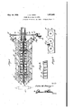
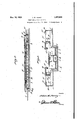
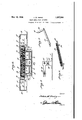
-May 10, 1932. -J. w. BERRY 1,857,566 i SHEET METAL PACK CONVEYEH i origina Filed oct. 14; 1929 s sheets-Sheet 1 May 10,1932- J. w. PERRY 1,857,566
SHEET 'METAL PACK CONVEYER y@riginal Filed Oct. 414, 1929 5 Sheets-Sheet 2 'i IIE-1 l Y .Inventor Jalan Werl* ttorney May 10, 1932. J. w. PERRY SHEET METAL PACK .CONVEYYER 3 Sheets-Sheet origina; Filed Oct. 14. 1929 MN v v Invenor 707222 Flor/y fj- Attorney UNITED STATES :omi w. '15mm-or e.' waar y .451mm;|\rr.'r-A1 .1ulcxool Application and ottone: 14,'1e2e, 'sn11v. mm. Renewed my as. resi. i
This inventiojii relates to a sheet metal pack Fi re 4 is va cross-sectional view showing yconveyer and more particularly to a device the c eaning brushesin engagement with'the f thisvcharacter which is ada ted for the metalpacks on the conveyer. I v urpose of conveying packso sheet metal Figure 5 is a detail view taken on the line u roma metal working furnace to a rolling 5-5.of Figure 1. f Y' mill, but it is to be understood that a. con- Figure 6 is a perspective view of one of veyer constructed in accordance with this inthe lower brushes. v Y' vention may be utilized for any purpose for Figure is a perspective view of one ofthe 1 m which it is found adapted. y bell'cranklevers f C j e0 An importantobject of the inventionis to Figure 8 is a detail view in elevationk show1-` provide, in a manner as hereinafter set forth, ing an end ortion of one of thelon 'tudinal a conveyer of the aforementioned character, guide mem rslocated on thesideo Athe conwhich is .adapted to be`associated with the, veyer. l V 1:, outlet of a sheet metalworking furnace and Figure9 is a fragmentarylongitudinal sec- 35 is provided with simultaneously adjustable tional view showing the position ofthelower- Y guide elements extending longitudinally on most brushes on the conveyen4 l 'opposite sides thereof for guiding the metal Referring to the' drawings in' detail, the packs as same travel over the conveyer from reference c aracter 1 designates the floor or f 20 saidifurnace to the rolling mill.` ground in front of the'furnace- (not-shown) 47o Another important object of the invention and in which is vformed a channel 2 of approresidesin the provision of inwardly projectpriate depth. An elon ated metal plate -3 exing guard iingers which extend over the contends' longitudinally tlrough the channel. 2 veyer and are provided with swivelled rollers and has mounted thereon the integral, 11pfor maintaining the packs on the conveyer. standing, longitudinal spaced flanges'V or ribs 75 Another impojrtant feature of the inven- 4 whichl provide channels A," B and G. A" tion resides in thev provision of opposed cleanplurality of longitudinally spaced rotary ing elements or brushes which are mounted on shafts 5 are journaled through' the upstan'dand shift with the guidemembers and are for ing flangesv 4and have mounted thereon, in-
engagement with thepacks as it travels over A termediate the pairs of said flanges, the cylinso the conveyer for the purpose of cleaning the drical rollers 6 vwhich project above the upper and lower surfaces thereof. ianges 4.
Other objects of the invention are to pro- Rearwardly ofthe channel 2 on the floor 1 vide a conveyer ofthe aforementioned charare mounted pairs'of longitudinally spaced v acter which, will be simple in construction, standards 7 and 8 andbetween each of the 85 strong, durable, eflicient in its useand which pairs of standards a horizontal shaft 9 and may be manufacturedat low cost.. A 10 extends. A pair of sprockets i711 are Other objects and advantages of the invenf mounted for rotation on the shaft'9 and have tion will become apparent from a study of the trained thereover the endless conveyer chains following specification, taken in connection 12 which extend into the metalworking fur- ,as Y with' the accompanying drawings, wherein nace and are adapted to convey `the -metal like characters of reference, designate correpacks therefro The upper and lower spending parts throughout the several views, strands of the chain 12 pass above and below and wherein i" the shaft 10 respectively. A sprocket 13 is 45 Figiire 1 is'a top plan view of a sheet metal 'j mounted on the intermediate portion of theI 95 pack conveyor constructed in accordance with shaft 10.A At the forward end offthe conthis invention. 7 veyer a pair of vertical standards 14 are Figure 2 is a longitudinal sectional view mounted between whichextends a horizontal taken centrally through the conveyer. shaft 15 upon which 1s mounted forlrotation Figureis'a cross-sectional view. the sprocket 16. l An endless cham 17 isA 10S l therefrom at right angles..v
trained over the sprockets13 and 16 and travel between the innermost of the vertical flanges 4 of the conveyer. The chain 17 is provided with a plurality of longitudinally spaced outwardly extending lugs 18. As will be seen in Figures 2 and 3 of the drawings, the chains 12, 17 and the conveyer roller 6 are all longitudinally aligned and in substantially the same horizontal plane.
A plurality of longitudinally spaced strips -19 are mounted on the floor 1 on opposite sides of the channel 2 and extend outwardly Longitudinally extending channel irons 20 are connected to the outer ends of the strips 19 with vtheir channelled sides disposed in'- wardly for the reception of said strips. A plurality of'arms 21 are pivotally connected, as' at 22 tothe upper sides of the channel bars 20 in longitudinally .spaced relation thereon and extend diagonally inwardly therefrom. inwardly of their free ends the arms 21 are pivotaly connected to channel bars 23, as at 24 and said bars 23 also have their channeled sides disposed inwardly and are of less height than the bars 20 and are shiftably supported stantia-lly a horizontal plane.
s f Arisea p in the strips 19. Vertical guide rollers 24 are ter from the upper and lower surfaces of the pack as it moves over the "conveyer 'a' plurality of opposed brushes are provdided and comlower brush including the bristles 28 which extend upwardly on opposite sides of theupper strand of the chain 17 -for engage- 1 ment with the lower surface of the pack and said bristles are mounted on an elongated bar 29 provided with the downwardly extending yapertured ears' 30for securing the brush on lthe upper end of the flanges 4 intermediate the rollers 6 thereon, as seen most clearly in i Figures'4 and 9 of the drawings. The'upper brushes comprise a pair of overlapping diagonally extending supporting bars 31 having the usual bristles depending therefrom and which are anchored, at one end, in the channel bars 23. f
A pair of vertical standards 32 are positioned rearwardly of the conveyer constituting this invention and on opposite sides thereof and have journaled therein the opposite endportions of a rotary shaft 33, the opposite end portionsof which are reversely' threaded as at 34. A guide rod 35 is also supported at of said shaft. The rearmost of newness its opposite ends in the standards 32 beneath the shaft 33 and in fparallel spaced relation thereto. A pair o forwardly extendin hifurcated arms 36 are threaded on the en portions of the shaft 33 and are maintained against rotation thereon and in a horizontally extending position through the medium of the depending guide iin ers 37 which s'lidably embrace the rod 35. s will be apparent, the arms 36 vare shifted longitudinally on the shaft 33 in opposite direction upon rotation the arms 21 have rigidly connected to the pivoted ends thereof the outwardly extending cranklevers 38 which extend between thefurcations on the 3@ arms 36 and have mounted therein cross pins 39 which extend into elongated slots 40 in said furcations. @ne Aend of the shaft 33 extends beyond its respectivesupportin standards 32 and has mounted thereon a vele gear 41. A standard 42 is mounted adjacentl the gear 41 and has journalled therein a crank handle 43 having mounted thereon a beveledv gear 44 which is in mesh with the gear 41.
The reference. numeral 45 designates, in 90 dotted line, one of therollers of the rolling. the sheet metalpacks are to be,
mill to which conducted.
Power may be chain 17 in any suitablemanner,
ing a belt driven pulley oneither of the shafts 10 or 15. It is to be understood that as many pairs of the brushes ma" hel mounted on the device as is desired an it is further Nunderstood that the device may be of any desired length and instead of being mounted on a floor or the groundthe same may be mounted on an elevated sup Vvort.
In the operation o the device, power is applied to the endless chain 17 for driving the same and when the sheet metal packs 25. .reach the end of theconveyer chain 12 from the-furnace, the same will'pass to the rollers 6 -journaled in the flanges 4 and the lugs 18 will engage the rear ends of the packs and ush the same longitudinally over the rollers.
he long-litudinal side edges of the packs will engage t 23 for maintaining said packs in proper alignment on the vrconveyer. For the purpose of' accommodating packs; of greater or less width, the crank handle 43 is actuated for applied for moving the as by mounte guide rollers 24 inthe channel bars:
rotating the shaft 33- andthe arms 36 move arms to which the crank levers 38 are con- !2 5 nected to swing in anl are on their pivots-22 and as all of said arms are connected together through the medium of the channel bars 23, the same will swing in unison and the channel"v bars 23having the guide rollers 24 journaled ,139'
' It is believed that the many advantages of 15 this invention will be readily understood, and although the preferred embodiment of the invention is as illustrated and described, it is to he understood that changes in the details or" construction may be had which will fall within the scope of the invention as claimed.
What is claimed is l.. A sheet metal pack conveyer of the character described comprising spaced series of conveyer rollers, a power chain extending longitudinally therebetween, stationary bars on opposite sides of the rollers inspaced rev v lation thereto, a series of arms pivotally connected at one end to each of the stationary bars in longitudinally spaced relation, shiftable bars pivotally connected to the arms inwardly of the stationary bars, guide rollers mounted on said shiftable bars and means for moving said arms and the shiftable bars in unison toward or from the conveyer'rollers.
, shifting said arms, stationary bars and guide A rollers toward or from the conveyer rollers.
3. A sheet metal pack conveyer of the character descrlbed comprlsing spaced serles of a conveyer constructed in accordance withn `posite longitudinal movement on said shaft 2. A sheet metal pack conveyerof the character descrlbed comprising spaced series of rollers in unison toward or from the'conveyer rollers.
4. A sheet metal pack conveyer of the character described. comprising spaced series of conveyer rollers, a power chain extending longitudinally therebetween, supporting strips extending laterally' from the conveyer rollers, stationary bars at the outer end thereof, horizontally swingable arms pivotally connected at one end to the stationary bars and extending inwardly over the' conveyer- Cil rollers, work engaging rollers pivotally depending from the inner end portions of the arms, shiftable bars pivotally connected to the arms intermediate their ends and mov- 0 ably supported on the strips, guide rollers on the shiftable bars and means for. shifting said arms, stationary bars, guide rollers and work engaging rollers toward or from the conveyer rollers in unison comprising 5 crank levers rigidly connected to certain of the arms, atransverserotary shaft adjacent said crank 'levers and having reversely threaded end portions, arms mounted for opco when the same is rotated, said arms operatively connected to the free end of the crank levers and means at one end ofthe rotary shaft for operating the same.
In testimony `whereof I aitix my signature. ai
JOHN W. PERRY.
conveyer rollers, a power chain extending longitudinally therebetween, supporting strips extending laterally from the conveyer 55 rollers, stationary bars at the outer ends thereof, horizontally swingable arms pivotally connected, at one end, to the stationary 'bars and extending inwardly over the conveyer rollers, work engaging rollers pivot- .30 allyI depending from the inner end portionl of the arms, shiftable bars pivotally connected to the arms intermediate their ends and movably supported on the strips, guide rollers on the shiftable bars and means for shiftingsaid arms, stationary bars and guide
Priority Applications (1)
| Application Number | Priority Date | Filing Date | Title |
|---|---|---|---|
| US399509A US1857566A (en) | 1929-10-14 | 1929-10-14 | Sheet metal pack conveyer |
Applications Claiming Priority (1)
| Application Number | Priority Date | Filing Date | Title |
|---|---|---|---|
| US399509A US1857566A (en) | 1929-10-14 | 1929-10-14 | Sheet metal pack conveyer |
Publications (1)
| Publication Number | Publication Date |
|---|---|
| US1857566A true US1857566A (en) | 1932-05-10 |
Family
ID=23579789
Family Applications (1)
| Application Number | Title | Priority Date | Filing Date |
|---|---|---|---|
| US399509A Expired - Lifetime US1857566A (en) | 1929-10-14 | 1929-10-14 | Sheet metal pack conveyer |
Country Status (1)
| Country | Link |
|---|---|
| US (1) | US1857566A (en) |
Cited By (13)
| Publication number | Priority date | Publication date | Assignee | Title |
|---|---|---|---|---|
| US2584754A (en) * | 1948-08-04 | 1952-02-05 | Spooner Dryer & Eng Co Ltd | Machine for the treating of web material |
| US2895593A (en) * | 1955-06-09 | 1959-07-21 | Rapids Standard Co Inc | Conveyors |
| US2932380A (en) * | 1958-06-09 | 1960-04-12 | Alvey Conveyor Mfg Co | Conveyor assembly |
| US3001636A (en) * | 1959-01-15 | 1961-09-26 | Delta Engineering Corp | Apparatus for channeling articles |
| US3034637A (en) * | 1955-06-09 | 1962-05-15 | Rapids Standard Co Inc | Conveyor |
| US3104007A (en) * | 1955-06-09 | 1963-09-17 | Rapids Standard Co Inc | Conveyor |
| US3197201A (en) * | 1960-11-07 | 1965-07-27 | Magnavox Co | Card transport system |
| US5211280A (en) * | 1992-03-13 | 1993-05-18 | Storcan Limitee | Adjustable guide rail apparatus for independently adjusting positions of first and second guide rails disposed respectively on opposite sides of the path of a conveyor |
| US5394979A (en) * | 1991-04-30 | 1995-03-07 | Prim Hall Enterprises, Inc. | Hopper loader |
| US5551555A (en) * | 1995-10-30 | 1996-09-03 | Roe, Incorporated | Guide system for packages on a conveyor system |
| US6059096A (en) * | 1997-06-25 | 2000-05-09 | Dillin Engineered Systems Corporation | Guide system for packages on a curved conveyor |
| US20150128537A1 (en) * | 2008-04-15 | 2015-05-14 | Krones Ag | Packaging machine for packs of beverage containers, a guide system for packaging packs and a method for packaging packs |
| US10988317B2 (en) * | 2018-04-19 | 2021-04-27 | Krones Ag | Format part for deflecting containers |
-
1929
- 1929-10-14 US US399509A patent/US1857566A/en not_active Expired - Lifetime
Cited By (13)
| Publication number | Priority date | Publication date | Assignee | Title |
|---|---|---|---|---|
| US2584754A (en) * | 1948-08-04 | 1952-02-05 | Spooner Dryer & Eng Co Ltd | Machine for the treating of web material |
| US2895593A (en) * | 1955-06-09 | 1959-07-21 | Rapids Standard Co Inc | Conveyors |
| US3034637A (en) * | 1955-06-09 | 1962-05-15 | Rapids Standard Co Inc | Conveyor |
| US3104007A (en) * | 1955-06-09 | 1963-09-17 | Rapids Standard Co Inc | Conveyor |
| US2932380A (en) * | 1958-06-09 | 1960-04-12 | Alvey Conveyor Mfg Co | Conveyor assembly |
| US3001636A (en) * | 1959-01-15 | 1961-09-26 | Delta Engineering Corp | Apparatus for channeling articles |
| US3197201A (en) * | 1960-11-07 | 1965-07-27 | Magnavox Co | Card transport system |
| US5394979A (en) * | 1991-04-30 | 1995-03-07 | Prim Hall Enterprises, Inc. | Hopper loader |
| US5211280A (en) * | 1992-03-13 | 1993-05-18 | Storcan Limitee | Adjustable guide rail apparatus for independently adjusting positions of first and second guide rails disposed respectively on opposite sides of the path of a conveyor |
| US5551555A (en) * | 1995-10-30 | 1996-09-03 | Roe, Incorporated | Guide system for packages on a conveyor system |
| US6059096A (en) * | 1997-06-25 | 2000-05-09 | Dillin Engineered Systems Corporation | Guide system for packages on a curved conveyor |
| US20150128537A1 (en) * | 2008-04-15 | 2015-05-14 | Krones Ag | Packaging machine for packs of beverage containers, a guide system for packaging packs and a method for packaging packs |
| US10988317B2 (en) * | 2018-04-19 | 2021-04-27 | Krones Ag | Format part for deflecting containers |
Similar Documents
| Publication | Publication Date | Title |
|---|---|---|
| US1857566A (en) | Sheet metal pack conveyer | |
| US2628709A (en) | Self-cleaning grooved rubber covered pulley | |
| US2152939A (en) | Dehydrating apparatus | |
| JPS57131653A (en) | Belt section which carry and decelerate folded product | |
| US3231267A (en) | Feeding device for ironing machines | |
| US3253432A (en) | Rug cleaning machine | |
| GB1514509A (en) | Machine for locating continuous web material in a taut or stretched condition on a plurality of frames | |
| US3252561A (en) | Feeder device | |
| US3399472A (en) | Spreading apparatus for flat work ironers | |
| US2722900A (en) | Sandwich making machine | |
| US4330934A (en) | Apparatus for pulling transverse fins onto a plurality of pipes | |
| US2834042A (en) | Sausage linking machine | |
| US1912020A (en) | Trash removing mechanism for water screens | |
| DE1155389B (en) | Conveyor for packaging machines | |
| US2065239A (en) | Bean slicing machine | |
| DE807512C (en) | Bag cleaning and de-encrusting machine | |
| US1988047A (en) | Apparatus for molding, shaping, and elongating dough rolls | |
| US1723967A (en) | Bread-wrapping machine | |
| US2195346A (en) | Machine for making loaves | |
| US1671038A (en) | Machine for snipping the ends from beans | |
| US1368096A (en) | Finishing-machine for pile fabrics | |
| US954159A (en) | Cane-stripper. | |
| US1599684A (en) | Pretzel cooker | |
| DE1785591C3 (en) | Feeding device for laundry items to a lack or the like. | |
| US1535325A (en) | Machine for shrinking felt articles |