US1857563A - Saw set - Google Patents
Saw set Download PDFInfo
- Publication number
- US1857563A US1857563A US528163A US52816331A US1857563A US 1857563 A US1857563 A US 1857563A US 528163 A US528163 A US 528163A US 52816331 A US52816331 A US 52816331A US 1857563 A US1857563 A US 1857563A
- Authority
- US
- United States
- Prior art keywords
- saw
- wheel
- plates
- teeth
- shaft
- Prior art date
- Legal status (The legal status is an assumption and is not a legal conclusion. Google has not performed a legal analysis and makes no representation as to the accuracy of the status listed.)
- Expired - Lifetime
Links
- 238000010276 construction Methods 0.000 description 2
Images
Classifications
-
- B—PERFORMING OPERATIONS; TRANSPORTING
- B23—MACHINE TOOLS; METAL-WORKING NOT OTHERWISE PROVIDED FOR
- B23D—PLANING; SLOTTING; SHEARING; BROACHING; SAWING; FILING; SCRAPING; LIKE OPERATIONS FOR WORKING METAL BY REMOVING MATERIAL, NOT OTHERWISE PROVIDED FOR
- B23D63/00—Dressing the tools of sawing machines or sawing devices for use in cutting any kind of material, e.g. in the manufacture of sawing tools
- B23D63/006—Saw teeth setting devices working with setting rollers
Definitions
- This invention relates to a saw set, the general object of the invention being to pro-' vide means whereby a saw can be easlly and quickly set through means of a pair of hold- 3 ing plates for the saw and between which the saw is placed and a carriage slidably ar-. ranged on the plate and carrying a saw set wheel which when rotated will cause the carriage to move along the plate and bring portions of the wheel into engagement with the teeth of the saw to set the same.
- This invention also consists in certain other features of construction andinthe combination and arrangement of the several parts, to
- Figure 2 is an end view thereof.
- Figure 3 is a top plan view, with parts in section, and the setting roller or wheel and its associated parts.
- Figure 4 is a perspective view of the wheel.
- FIG. 5 is a view of one of the bearings.
- the numeral 1 indicates the base of the device and the numeral 2 indicates a pair of uprights fastened to the base and having their upper portions forked to receive the two plates 3 which are fastened I a to the uprights as shown at 4.
- Each plate has'an outwardly extending flange 5 at its upper edge and the plates are spaced apart so that a saw .such as shown at A can be placed between the plates.
- the lower portion of each plate is formed with the V-shaped notches 6 for exposing portions of the saw so that these portions can be engaged by a substantially U-shaped spring 7 which is fas-' tened to the base and has its end curved to Q engage the rear edge of the saw as clearly shown in Figure 1.
- a substantially channel shaped frame or carriage 8 is adapted to be placed over the flanged upper edges of the two plates 3 with the flanges of the frame 8 bent inwardly to 31 e in Nd StZBQ-IGS;
- the vsidesfof this-frame are formed with the upwardly extend ng portions 9 which have'circular openings thereinflto receive the flanged bearing 1 members 10 through whichthe shaft 11 passes.
- a handle :12 isyconn-ected' to one end of the shaft and a collar 13 is conneetedto the other end'by azset screw 14st 'thatwby removing the setscrew and pulling" off the collar the an shaft canrberemovedt
- a wheel 15 has a square opening 16 in its .hub .17 for receiving 5 a square part of the shaft and the periphery of this wheel is corrugated asshown at 18 to 8 form the teeth engaging .parts which act to set the teeth of the saw;
- Each corrugation v is of. s i-n Figurel.. 1.
- the hub is I e'X-teriorly threaded 'to' receive I the hubs '19, of theidisksQO whichengage the-7e V faces of the-wheel 15 as shown in Figure 3. These disks acting to-close the open sides of the corrugations. as shown in' Figure It will of coursebe understood that a nuIn-' ber of these wheelsmustbe furnished with'ra the device, so the device canbe used for setting saws of different sizes.
- V V p A saw setting device comprising a sup port, a pair of vertically arranged plates supported in spaced relation by said support and adapted to receive a sawbetween them, the upper ends of the plates having outwardly extending flanges thereon, a frame slidably arranged on the upper edges of the plates and engaging the flanges, a shaft rotatably ark ranged -.in the second frame, a saw settingv wheelconnected with the shaft and having a hub extending outwardly from each side 7 thereof, a pairof disks between'which the wheel is arranged, means for detachably connecting the disks to said hub and a spring attached to the support andengaging the rear edge of the saw.
- a saw setting device comprising a base, forked uprights on the base, a pair of spaced plates extending between the prongs of the fork and fastened thereto in spaced relation for receiving a saw between them, the upper edges of the plates having outwardly extending flanges thereon, a frame slidably arranged on the upper edges of the plate and having portions engaging the flanges, a shaft rotatably arranged in the second frame, a handle on the shaft, a setting wheel having a hub extending outwardly on each side thereof,
- said hub being fastened to the shaft, a pair of disks on said hub and between which the wheel is located, the periphery of the wheel being corrugated with each corrugation having a sloping-tooth engaging portion with V saidv sloping portion alternately arranged, a
- said spring on the base, said spring being of U- shape with the ends of its limbs engaging the rear edge of a saw.
Landscapes
- Engineering & Computer Science (AREA)
- Mechanical Engineering (AREA)
- Sawing (AREA)
Description
May 10, 1932. 5 oL ER SAW SET Filed April 6, 1931 2 Sheets-Sheet 1 L Inventor y 10, 1932. B. H. OLIVER 1 857,563
SAW SET Filed April 6, 1931 2 Sheets-Sheet 2 I g- 20 i 4.
Inventor v ww im.
Patented May 10, 1932 BENJAMIN HQ OLIVER,
SAW
Application filed April 6,
This invention relates to a saw set, the general object of the invention being to pro-' vide means whereby a saw can be easlly and quickly set through means of a pair of hold- 3 ing plates for the saw and between which the saw is placed and a carriage slidably ar-. ranged on the plate and carrying a saw set wheel which when rotated will cause the carriage to move along the plate and bring portions of the wheel into engagement with the teeth of the saw to set the same.
This invention also consists in certain other features of construction andinthe combination and arrangement of the several parts, to
be hereinafter fully described, illustrated in.
i the accompanying drawings and specifically pointed out in the appended claims.
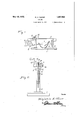
In describing the invention in detail, reference will be had to the accompanying drawings wherein like characters denote like or corresponding parts throughout the several views, and in which I Figure 1 is a side elevation of the device.
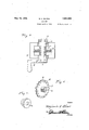
Figure 2 is an end view thereof. 7 Figure 3 is a top plan view, with parts in section, and the setting roller or wheel and its associated parts.
Figure 4 is a perspective view of the wheel.
Figure 5 is a view of one of the bearings. In these drawings, the numeral 1 indicates the base of the device and the numeral 2 indicates a pair of uprights fastened to the base and having their upper portions forked to receive the two plates 3 which are fastened I a to the uprights as shown at 4. Each plate has'an outwardly extending flange 5 at its upper edge and the plates are spaced apart so that a saw .such as shown at A can be placed between the plates. The lower portion of each plate is formed with the V-shaped notches 6 for exposing portions of the saw so that these portions can be engaged by a substantially U-shaped spring 7 which is fas-' tened to the base and has its end curved to Q engage the rear edge of the saw as clearly shown in Figure 1.
A substantially channel shaped frame or carriage 8 is adapted to be placed over the flanged upper edges of the two plates 3 with the flanges of the frame 8 bent inwardly to 31 e in Nd StZBQ-IGS;
holdthe frame on the plate. The vsidesfof this-frame are formed with the upwardly extend ng portions 9 which have'circular openings thereinflto receive the flanged bearing 1 members 10 through whichthe shaft 11 passes.
A handle :12 isyconn-ected' to one end of the shaft and a collar 13 is conneetedto the other end'by azset screw 14st 'thatwby removing the setscrew and pulling" off the collar the an shaft canrberemovedt A wheel 15 has a square opening 16 in its .hub .17 for receiving 5 a square part of the shaft and the periphery of this wheel is corrugated asshown at 18 to 8 form the teeth engaging .parts which act to set the teeth of the saw; Each corrugation v is of. s i-nFigurel.. 1. V Q The hub is I e'X-teriorly threaded 'to' receive I the hubs '19, of theidisksQO whichengage the-7e V faces of the-wheel 15 as shown in Figure 3. These disks acting to-close the open sides of the corrugations. as shown in'Figure It will of coursebe understood that a nuIn-' ber of these wheelsmustbe furnished with'ra the device, so the device canbe used for setting saws of different sizes. 5 t a From the foregoing it will be seen that'as I j the wheel is rotated the'teeth of .the saw.= will be engagedbetween'thesloping faces of the g 7 corrugations and the disks so that all the teeth will be set accurately and to the same degree and with this device the saw teeth can be set with great speed. As the carriage 8 is placed on the flanged upper edgesof the 5 plate 8, the plates are pressed toward each other so as to frictionally engage the saw and this withthe spring? acts to prevent the saw from moving downwardly as its teeth are engaged by the setting wheel. The carriage is moved along the upper portion of the plate 8, and during this movement the wheel will engage the teeth and set the same, the resistance offered by the teeth to the movement of the wheel as its shaft is turned by the handle 12- to cause the bearings to move along the upper parts of the plates 3.
It is thought from the foregoing description that the advantages and novel features of the invention will be readily apparent. If?
quare'sh'ape in crosssectionasshown' It is to be understood that changes may be made in the construction and in the combination and arrangement of the several parts, provided that such changes fall within the scope of the appended claims.
Having thus described my invention what I claim as new is: V V p 1. A saw setting device comprising a sup port, a pair of vertically arranged plates supported in spaced relation by said support and adapted to receive a sawbetween them, the upper ends of the plates having outwardly extending flanges thereon, a frame slidably arranged on the upper edges of the plates and engaging the flanges, a shaft rotatably ark ranged -.in the second frame, a saw settingv wheelconnected with the shaft and having a hub extending outwardly from each side 7 thereof, a pairof disks between'which the wheel is arranged, means for detachably connecting the disks to said hub and a spring attached to the support andengaging the rear edge of the saw. v
2. A saw setting device comprising a base, forked uprights on the base, a pair of spaced plates extending between the prongs of the fork and fastened thereto in spaced relation for receiving a saw between them, the upper edges of the plates having outwardly extending flanges thereon, a frame slidably arranged on the upper edges of the plate and having portions engaging the flanges, a shaft rotatably arranged in the second frame, a handle on the shaft, a setting wheel having a hub extending outwardly on each side thereof,
said hub being fastened to the shaft, a pair of disks on said hub and between which the wheel is located, the periphery of the wheel being corrugated with each corrugation having a sloping-tooth engaging portion with V saidv sloping portion alternately arranged, a
spring on the base, said spring being of U- shape with the ends of its limbs engaging the rear edge of a saw.
In testimony whereof I afliX my signature.
BENJAMIN H. OLIVER.-
Priority Applications (1)
| Application Number | Priority Date | Filing Date | Title |
|---|---|---|---|
| US528163A US1857563A (en) | 1931-04-06 | 1931-04-06 | Saw set |
Applications Claiming Priority (1)
| Application Number | Priority Date | Filing Date | Title |
|---|---|---|---|
| US528163A US1857563A (en) | 1931-04-06 | 1931-04-06 | Saw set |
Publications (1)
| Publication Number | Publication Date |
|---|---|
| US1857563A true US1857563A (en) | 1932-05-10 |
Family
ID=24104500
Family Applications (1)
| Application Number | Title | Priority Date | Filing Date |
|---|---|---|---|
| US528163A Expired - Lifetime US1857563A (en) | 1931-04-06 | 1931-04-06 | Saw set |
Country Status (1)
| Country | Link |
|---|---|
| US (1) | US1857563A (en) |
-
1931
- 1931-04-06 US US528163A patent/US1857563A/en not_active Expired - Lifetime
Similar Documents
| Publication | Publication Date | Title |
|---|---|---|
| US2532982A (en) | Motor operated hedge or grass trimmer | |
| US1857563A (en) | Saw set | |
| US2627323A (en) | T-square and parallel straightedge combination | |
| US2075301A (en) | Lawn edge trimmer | |
| SE444083B (en) | REMSOR CUTTING DEVICE | |
| US2684533A (en) | Linoleum cutter and trimmer | |
| US2568468A (en) | Sidewalk edger and trimmer | |
| US3537244A (en) | Lawn edging and trimming device | |
| US1590918A (en) | Gear puller | |
| US2353345A (en) | Lawn renovating machine | |
| US1426911A (en) | Sharpening device | |
| US1956686A (en) | Razor blade sharpener | |
| US2184663A (en) | Print drying apparatus | |
| US2780034A (en) | Lawnmower sharpener | |
| US2935101A (en) | Core veneer band saw | |
| US3737931A (en) | Honeycomb uncapping machine | |
| US1241607A (en) | Bicycle-skate. | |
| US2072677A (en) | Food handling apparatus | |
| US1856435A (en) | Lawn edger and groover | |
| US2251023A (en) | Grass cutter | |
| US1964627A (en) | Scissors sharpener | |
| US2556600A (en) | Wallpaper machine | |
| US2959150A (en) | Methods and apparatus for preparing brake lining | |
| US1416567A (en) | Speed-regulating device | |
| US1878439A (en) | Portable garden hoe vise |