US1857559A - Moving picture apparatus - Google Patents
Moving picture apparatus Download PDFInfo
- Publication number
- US1857559A US1857559A US296143A US29614328A US1857559A US 1857559 A US1857559 A US 1857559A US 296143 A US296143 A US 296143A US 29614328 A US29614328 A US 29614328A US 1857559 A US1857559 A US 1857559A
- Authority
- US
- United States
- Prior art keywords
- shaft
- film
- prism
- axes
- shafts
- Prior art date
- Legal status (The legal status is an assumption and is not a legal conclusion. Google has not performed a legal analysis and makes no representation as to the accuracy of the status listed.)
- Expired - Lifetime
Links
- 230000008878 coupling Effects 0.000 description 2
- 238000010168 coupling process Methods 0.000 description 2
- 238000005859 coupling reaction Methods 0.000 description 2
- 238000006073 displacement reaction Methods 0.000 description 2
- 235000007575 Calluna vulgaris Nutrition 0.000 description 1
- 238000010586 diagram Methods 0.000 description 1
- 230000000694 effects Effects 0.000 description 1
- 238000012986 modification Methods 0.000 description 1
- 230000004048 modification Effects 0.000 description 1
- 230000003287 optical effect Effects 0.000 description 1
- 230000002093 peripheral effect Effects 0.000 description 1
Images


Classifications
-
- G—PHYSICS
- G03—PHOTOGRAPHY; CINEMATOGRAPHY; ANALOGOUS TECHNIQUES USING WAVES OTHER THAN OPTICAL WAVES; ELECTROGRAPHY; HOLOGRAPHY
- G03B—APPARATUS OR ARRANGEMENTS FOR TAKING PHOTOGRAPHS OR FOR PROJECTING OR VIEWING THEM; APPARATUS OR ARRANGEMENTS EMPLOYING ANALOGOUS TECHNIQUES USING WAVES OTHER THAN OPTICAL WAVES; ACCESSORIES THEREFOR
- G03B41/00—Special techniques not covered by groups G03B31/00 - G03B39/00; Apparatus therefor
- G03B41/02—Special techniques not covered by groups G03B31/00 - G03B39/00; Apparatus therefor using non-intermittently running film
- G03B41/04—Special techniques not covered by groups G03B31/00 - G03B39/00; Apparatus therefor using non-intermittently running film with optical compensator
-
- Y—GENERAL TAGGING OF NEW TECHNOLOGICAL DEVELOPMENTS; GENERAL TAGGING OF CROSS-SECTIONAL TECHNOLOGIES SPANNING OVER SEVERAL SECTIONS OF THE IPC; TECHNICAL SUBJECTS COVERED BY FORMER USPC CROSS-REFERENCE ART COLLECTIONS [XRACs] AND DIGESTS
- Y10—TECHNICAL SUBJECTS COVERED BY FORMER USPC
- Y10T—TECHNICAL SUBJECTS COVERED BY FORMER US CLASSIFICATION
- Y10T74/00—Machine element or mechanism
- Y10T74/18—Mechanical movements
- Y10T74/18056—Rotary to or from reciprocating or oscillating
- Y10T74/18072—Reciprocating carriage motions
Definitions
- This invention relates to moving picture low each individual picture of the film a disapparatus of the type in which the film is contance corresponding to the height ofthe pictinuously moved. ture, the prisms being then rapidly turned
- the object of the invention is to provide back again to repeat the same operation in re- 5 simpleineans to compensate for the motion of spect to the next picture.
- Fig.1 the inieach individual picture or photograph so that tial position of the beam as regards one icit' will be stationary on the screen.
- a prism 11 is provided situated and the screen of a prism or mirror or a sysafter the objective 10 which is rotatable about tem of prisms or mirrors which is or are ahorizontal axis and is caused toswing about movable in such a way as to reflect said movsaid axis synchronously with the movement ing beam on the same or substantially the of the'prisms 4, 5 in such a way as to reflect '20 same place on the screen. the beam towards the same or substantially In the accompanying drawings a moving the same place of the screen.
- Fig. 1 is a diavided a stationary prism 12 to reflect the beam gram illustrating the optical system of the in adirection suitable for the projection, as 25 apparatus.
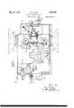
- Fig.2 is a longitudinal section of shown in Fig. 1. As shown in'this figure a the apparatus on the line II-II in Fig. 3. certain displacement of each individual pic- Fig. 3 is a horizontal section of the apparatus ture is taken place, viz. from the dottedposion the line III-III in Fig. 2.
- Fig. 1 is a diavided a stationary prism 12 to reflect the beam gram illustrating the optical system of the in adirection suitable for the projection, as 25 apparatus.
- Fig.2 is a longitudinal section of shown in Fig. 1.
- certain displacement of each individual pic- Fig. 3 is a horizontal section of the apparatus ture is taken place, viz. from the dottedposion the line III-III in Fig. 2.
- Fig. 5 is a detail section on to a neglectable amount by suitable adjustthe line V- in Fig. 3. ment of the rotation of the prism 11 and,
- the numeral 1 indicates a source of After the principle of the operation of the light the cone of light. from which is concenapparatus has thus been described above the trated by the lens 2 as a beam. Said beam is desi n of the apparatus will now be more thrown through an opening of the same size neai y explained with reference to Figs. 2-5 as a picture of the film which is formed in a of the drawings. wall .3, and behind said Wall the beam en-
- the reference numeral 20 indicates the counters atotal'reflecting prism 4.
- the light horizontal main shaft of the apparatus reflected by this prism is reflected by a simiwhich may be operated either manually, as lar prism 5 upon the film .6 which is assumed by means of the hand lever 21 geared to the s to move continuously from. the reel 7 to the shaft 20. or electrically as by a motor (not reel 8.
- the prisms 4 and 5 are caused, as by shown) the shaft 22 of which directl coumeans now shown, to move simultaneously at pled to the shaft 20 by a preferably, exible equal angular speed in the same direction. clutch 23.
- the prism 11 is secured to a shaft 35 rotatabl mounted in a frame 36 that may slide in t e longitudinal direction of the machine.
- the shaft 35 is connected by a crank shaped member 36 to a shaft 38 extending parallel to the shaft 35 which ismounted in the machine frame at 39 and 40.
- the shaft 38 is shaped as a strap 41 in which there is mounted a shaft 42 extending at right angles to the shaft 38.
- the shaft 42 carries a cam 43 and a toothed wheel 44 rigidly connected to said cam.
- the toothed wheel 44 meshes in a toothed wheel 45 secured to the,
- a bracket 46 Attached to the machine frame at each side of the cam 43 and the toothed wheel 44 is a bracket 46, and mounted in eachsuch bracket upon journals at right angles to the shaft 38 is a rotatable roller 47 to guide the cam by engaging it from the side near its periphery. Attached to the shaft of each guide roller 47 is a bevel gear wheel 48 and 49, respectively, meshing in bevel gear wheels 50 and 51, respectively secured to the shaft 20.
- the means to control the prisms 4 and 5 are of exactly the same design as described above in connection with the prism 11 and the details of said means areindicated by the same reference numeral as. those used in connection with the control means of the prism 11 with addition of the index 1.
- the prism 4 is connected to the prism 5 by means of a disc 52 secured to the shaft 35 a similar disc 54 secured to the shaft 53 of prism 4, and rods 55 interconnecting the discs.
- the rotation of the driving shaft 20 is transmitted through the worm gearing 24, 26 and the toothed gearings 28, 30 and 27, 29 to the film moving drums 33, 34 so that the film will be moved continuously. Furthermore, the movement is transmitted through the toothed wheels 44, 45 to the cams 43 to rotate same. Through the- .intermedium of the toothed gearings 48,50 and 49, 51 the guide rollers 47 are also rotated at the same peripheral speed as the cams 43 whereby the wearing will be reduced to a minimum. The rotation of the cams 43 will cause the shafts 38, 38' with the straps 41,41 to vibrate.
- the cams 43, 43 are of such a shape as to cause the straps to first swing in one direction through a certain angle and then more rapidly return in the opposite direction to their initial position.
- the vibration of the straps 41 is transmitted by means of.
- the prism carrying frames 36, 36 are, as already stated, adjustable in the longitudinal direction of the machine and their adjustment maybe effected by means of hand wheels 60, 61 and 62, 63, respectively. This will permit adjustment of the vibration of the prisms, as the displacement of the frame will changeposition of the shaft 38 of the strap 41 relatively'to the shaft 35 of the prisms thereb effecting a variation of the effective length of the clutch member 37.
- the prisms may be replaced by mirrors and, furthermore, the design of the means for operating the prisms or mirrors -may be different from that illustrated.
- an objective other light reflecting means situated between-said objective' and a screen, and rotatably mounted parallel shafts to carry said li ht reflecting,
- means, means to operate said s afts in synchronlsm comprising positively driven camdiscs rotatably mounted in straps rotatable about axes at right angles to the axes of the respective cam discs, and stationary means to guide said cam discs so as to cause them to oscillate about their axes upon rotation of the cam discs about their own axes, and connections between said stra s and the rotatable shafts carrying the light reflecting means.
- a moving picture apparatus of the type having a source of light, means to continuously move the film, a system-of light reflecting means situated between said source and the film, an objective and other ligh reflecting means situated between said ob jective and a screen, rotatably mounted shafts to carry said light-reflecting means, means to operate said shafts comprising positively driven cam-discs rotatably mounted in straps rotatable about axes at right angles to the axes of the respective camdiscs, stationary means to guide said cam discs so as to cause the straps to oscillate about their axes upon the rotation of the camdiscs about their own axes, and adjustable connections between said straps and the rotatable shafts carrying the light reflecting means.
- a moving picture apparatus of the type having a source of light, means to contmuously move the film, a system of light reflecting means situated between said source and the film, an objective, other light reflecting means situated between said objective and a screen, and rotatably mounted parallel shafts to carry said light reflecting means, means to operate said shafts comprising positively driven cam discs rotatably mounted in straps rotatable about axes at right angles to the axes of the res ctive cam discs, stationary' rollers to gui e said cam discs so as to cause said straps to oscillate about their axes upon the rotation of the cam discs about their own axes, and'crank shaped cou lings connecting the shafts carrying the lig t reflecting means and the shaft of the stra s,
Landscapes
- Physics & Mathematics (AREA)
- General Physics & Mathematics (AREA)
- Projection Apparatus (AREA)
Description
May 10, 1932. K. o. LEON 1,357,559
Y I MOVING PICTU RE APPARATUS Filed July so. 1928 4 Sheets-Sheet 1 May 10, 1932. K. o. LEON MOVING PICTURE APPARATUS 4 Sheets-Sheet 2 Filed July so, 1928 May 10, 1932. g, o, LEON 1,857,559
MOVING PICTURE APPARATUS Filed July 30, 1928 4 Sheets-Sheet 3 2a E! E May 10, 1932. K. o. LEON 1,857,559
MOVING PICTURE APPARATUS Filed July so, 1928 4 Sheets-Sheet 4 Fatented May 10,1932 i i UNITED. STATES PAT ENT. OFFICE I osm LFDN, or Lrnirorme, swEDnN H movnwe rro'roan APPARATUS Application filed J'uly 30, 1928, Serial No. 296,143, and in Sweden Au'g'ust 4, 1927.
This invention relates to moving picture low each individual picture of the film a disapparatus of the type in which the film is contance corresponding to the height ofthe pictinuously moved. ture, the prisms being then rapidly turned The object of the invention is to provide back again to repeat the same operation in re- 5 simpleineans to compensate for the motion of spect to the next picture. In Fig.1 the inieach individual picture or photograph so that tial position of the beam as regards one icit' will be stationary on the screen. To this ture of the film is indicated by dotted lines end provision is made between the source of and the corresponding final position by full light and the film of a system of movable mirlines. 10 rors or prisms-to project a beam of light The beam after having passed through the through the film, causing said beam, while film is conver ed by the lens 9 towards the moving parallel to itself, to follow each indiobjective 10 w iere it will be given the angle vidual photograph or picture during a sufiiof picture necessary for the magnification.
cient portion of its movement. Furthermore, In order to prevent the picture from moving l5 rovision is made between the projecting lens on the screen a prism 11 is provided situated and the screen of a prism or mirror or a sysafter the objective 10 which is rotatable about tem of prisms or mirrors which is or are ahorizontal axis and is caused toswing about movable in such a way as to reflect said movsaid axis synchronously with the movement ing beam on the same or substantially the of the'prisms 4, 5 in such a way as to reflect '20 same place on the screen. the beam towards the same or substantially In the accompanying drawings a moving the same place of the screen. Between the picture apparatus according to this invention prism 11 and the screen 13 there may be prois shown by way of example. Fig. 1 is a diavided a stationary prism 12 to reflect the beam gram illustrating the optical system of the in adirection suitable for the projection, as 25 apparatus. Fig.2 isa longitudinal section of shown in Fig. 1. As shown in'this figure a the apparatus on the line II-II in Fig. 3. certain displacement of each individual pic- Fig. 3 is a horizontal section of the apparatus ture is taken place, viz. from the dottedposion the line III-III in Fig. 2. Fig. 4 is a tion to the full line position, such displacecross section of the apparatus on the line ment, however, may be eliminated or reduced IV-IV in Fi .3. Fig. 5is a detail section on to a neglectable amount by suitable adjustthe line V- in Fig. 3. ment of the rotation of the prism 11 and,
With reference to the diagram shown in eventually, also of the prism 12. Fig. 1, the numeral 1 indicates a source of After the principle of the operation of the light the cone of light. from which is concenapparatus has thus been described above the trated by the lens 2 as a beam. Said beam is desi n of the apparatus will now be more thrown through an opening of the same size neai y explained with reference to Figs. 2-5 as a picture of the film which is formed in a of the drawings. wall .3, and behind said Wall the beam en- The reference numeral 20 indicates the counters atotal'reflecting prism 4. The light horizontal main shaft of the apparatus reflected by this prism is reflected by a simiwhich may be operated either manually, as lar prism 5 upon the film .6 which is assumed by means of the hand lever 21 geared to the s to move continuously from. the reel 7 to the shaft 20. or electrically as by a motor (not reel 8. The prisms 4 and 5 are caused, as by shown) the shaft 22 of which directl coumeans now shown, to move simultaneously at pled to the shaft 20 by a preferably, exible equal angular speed in the same direction. clutch 23. Secured to the shaft 20 is a worm The speed of rotation is so adjusted relative- 24 meshing with a worm'wheel 26 carried by ly to the movement of the film that the beam a vertical shaft 25. Secured to the shaft 25 reflected upon the film by the prism 5 will are two bevel gear'wheels 27 and 28 (see Fig. l move parallel to itselfat the same speed as 4) meshing in the bevel gear wheels 29 and 50 the film! in such a way that the beam will fol- 30, respectively, secured to the shafts 31 and ment of the prisms are designed as follows,
it being noted that the means to erate the prism 11 will be first described (re erence being had to Figs. 3 and 5). The prism 11 is secured to a shaft 35 rotatabl mounted in a frame 36 that may slide in t e longitudinal direction of the machine. The shaft 35 is connected by a crank shaped member 36 to a shaft 38 extending parallel to the shaft 35 which ismounted in the machine frame at 39 and 40. Intermediate between its ends,
the shaft 38 is shaped as a strap 41 in which there is mounted a shaft 42 extending at right angles to the shaft 38. The shaft 42 carries a cam 43 and a toothed wheel 44 rigidly connected to said cam. The toothed wheel 44 meshes in a toothed wheel 45 secured to the,
The operation of the apparatus is as follows:
The rotation of the driving shaft 20 is transmitted through the worm gearing 24, 26 and the toothed gearings 28, 30 and 27, 29 to the film moving drums 33, 34 so that the film will be moved continuously. Furthermore, the movement is transmitted through the toothed wheels 44, 45 to the cams 43 to rotate same. Through the- .intermedium of the toothed gearings 48,50 and 49, 51 the guide rollers 47 are also rotated at the same peripheral speed as the cams 43 whereby the wearing will be reduced to a minimum. The rotation of the cams 43 will cause the shafts 38, 38' with the straps 41,41 to vibrate. The cams 43, 43 are of such a shape as to cause the straps to first swing in one direction through a certain angle and then more rapidly return in the opposite direction to their initial position. The vibration of the straps 41 is transmitted by means of. the
' The prism carrying frames 36, 36 are, as already stated, adjustable in the longitudinal direction of the machine and their adjustment maybe effected by means of hand wheels 60, 61 and 62, 63, respectively. This will permit adjustment of the vibration of the prisms, as the displacement of the frame will changeposition of the shaft 38 of the strap 41 relatively'to the shaft 35 of the prisms thereb effecting a variation of the effective length of the clutch member 37.
It is further to be noted that modifications may be made without departing from the principle or scope of the invention. For instance, the prisms may be replaced by mirrors and, furthermore, the design of the means for operating the prisms or mirrors -may be different from that illustrated.
source and the film, an objective, other light reflecting means situated between-said objective' and a screen, and rotatably mounted parallel shafts to carry said li ht reflecting,
means, means to operate said s afts in synchronlsm comprising positively driven camdiscs rotatably mounted in straps rotatable about axes at right angles to the axes of the respective cam discs, and stationary means to guide said cam discs so as to cause them to oscillate about their axes upon rotation of the cam discs about their own axes, and connections between said stra s and the rotatable shafts carrying the light reflecting means.
2. In a moving picture apparatus of the type having a source of light, means to continuously move the film, a system-of light reflecting means situated between said source and the film, an objective and other ligh reflecting means situated between said ob jective and a screen, rotatably mounted shafts to carry said light-reflecting means, means to operate said shafts comprising positively driven cam-discs rotatably mounted in straps rotatable about axes at right angles to the axes of the respective camdiscs, stationary means to guide said cam discs so as to cause the straps to oscillate about their axes upon the rotation of the camdiscs about their own axes, and adjustable connections between said straps and the rotatable shafts carrying the light reflecting means.
3. type having a source of light, means to con- In a moving picture apparatus of the tinuously move the film, a system of light refleeting meanssituated betweensaid source of the film, an objective, other light reflecting means situated between said objective and a screen, and rotatably mounted parallel shafts to carry said light reflecting means, means to operate said shafts comprising positively driven cam-discs rotatably mounted. in straps rotatable about axes at right angles to the axes of the respective cam discs, .sta-
tionary guiding means to cause said straps to oscillate'about their axes upon the rotation of the cam discs about their own axes,
. and crank shaped couplings connecting the shafts carrying the light re ecting means and the shafts of the straps, said shafts being laterally adjustable relatively to each other to effect variation of the ratio of gearing of said couplings.
4; In a moving picture apparatus of the type having a source of light, means to contmuously move the film, a system of light reflecting means situated between said source and the film, an objective, other light reflecting means situated between said objective and a screen, and rotatably mounted parallel shafts to carry said light reflecting means, means to operate said shafts comprising positively driven cam discs rotatably mounted in straps rotatable about axes at right angles to the axes of the res ctive cam discs, stationary' rollers to gui e said cam discs so as to cause said straps to oscillate about their axes upon the rotation of the cam discs about their own axes, and'crank shaped cou lings connecting the shafts carrying the lig t reflecting means and the shaft of the stra s,
-said light reflecting means together wlthname.
their shafts being mounted in adjustable frames to enable variation of the ratioof.
gearings of said couplin r In testimony-whereo? I have signed my KARLOSKAR LEON.
Applications Claiming Priority (1)
| Application Number | Priority Date | Filing Date | Title |
|---|---|---|---|
| SE1857559X | 1927-08-04 |
Publications (1)
| Publication Number | Publication Date |
|---|---|
| US1857559A true US1857559A (en) | 1932-05-10 |
Family
ID=20423804
Family Applications (1)
| Application Number | Title | Priority Date | Filing Date |
|---|---|---|---|
| US296143A Expired - Lifetime US1857559A (en) | 1927-08-04 | 1928-07-30 | Moving picture apparatus |
Country Status (1)
| Country | Link |
|---|---|
| US (1) | US1857559A (en) |
Cited By (1)
| Publication number | Priority date | Publication date | Assignee | Title |
|---|---|---|---|---|
| US2523694A (en) * | 1946-07-09 | 1950-09-26 | Gras Adrien Louis | Optical rectifier for motion-picture projectors |
-
1928
- 1928-07-30 US US296143A patent/US1857559A/en not_active Expired - Lifetime
Cited By (1)
| Publication number | Priority date | Publication date | Assignee | Title |
|---|---|---|---|---|
| US2523694A (en) * | 1946-07-09 | 1950-09-26 | Gras Adrien Louis | Optical rectifier for motion-picture projectors |
Similar Documents
| Publication | Publication Date | Title |
|---|---|---|
| US1879793A (en) | Motion picture apparatus | |
| US2660088A (en) | Apparatus for continuous cinematographic projection | |
| US1950374A (en) | Production of stereoscopic pictures | |
| US1857559A (en) | Moving picture apparatus | |
| US1840799A (en) | Optical device | |
| US1909222A (en) | Photographic camera | |
| US1259365A (en) | Cinematograph apparatus. | |
| US2194737A (en) | Motion picture apparatus | |
| US2868066A (en) | Optical rectifier | |
| US1818410A (en) | Optical apparatus | |
| US2184641A (en) | Stereoscopic moving picture apparatus | |
| US2460864A (en) | Motion-picture projecting system | |
| US1485195A (en) | Optical rectifier for cinematographic apparatus | |
| US2441013A (en) | Cinematographic rotatable prism projector | |
| US1154835A (en) | Cinematographic apparatus. | |
| US2966095A (en) | Shutter for multi lens cameras | |
| US1850641A (en) | Apparatus for taking cinematographic film views from variable postitions | |
| US1690602A (en) | Optical instrument | |
| US1476237A (en) | Means for the projection of cinematograph films | |
| US2070033A (en) | Motion picture apparatus | |
| US2085594A (en) | Optical apparatus | |
| US1974574A (en) | Lens for imaging spaced objects in register | |
| US1842255A (en) | Cinematographic projection system with continuous travel of the film | |
| US1797066A (en) | Film-projecting machine | |
| US3277780A (en) | Apparatus for strip-by-strip rectification of photograms |