US1857556A - Power plant - Google Patents
Power plant Download PDFInfo
- Publication number
- US1857556A US1857556A US281902A US28190228A US1857556A US 1857556 A US1857556 A US 1857556A US 281902 A US281902 A US 281902A US 28190228 A US28190228 A US 28190228A US 1857556 A US1857556 A US 1857556A
- Authority
- US
- United States
- Prior art keywords
- air
- fuel
- combustion chamber
- chamber
- sections
- Prior art date
- Legal status (The legal status is an assumption and is not a legal conclusion. Google has not performed a legal analysis and makes no representation as to the accuracy of the status listed.)
- Expired - Lifetime
Links
Images


Classifications
-
- F—MECHANICAL ENGINEERING; LIGHTING; HEATING; WEAPONS; BLASTING
- F23—COMBUSTION APPARATUS; COMBUSTION PROCESSES
- F23R—GENERATING COMBUSTION PRODUCTS OF HIGH PRESSURE OR HIGH VELOCITY, e.g. GAS-TURBINE COMBUSTION CHAMBERS
- F23R3/00—Continuous combustion chambers using liquid or gaseous fuel
- F23R3/42—Continuous combustion chambers using liquid or gaseous fuel characterised by the arrangement or form of the flame tubes or combustion chambers
- F23R3/44—Combustion chambers comprising a single tubular flame tube within a tubular casing
-
- F—MECHANICAL ENGINEERING; LIGHTING; HEATING; WEAPONS; BLASTING
- F23—COMBUSTION APPARATUS; COMBUSTION PROCESSES
- F23R—GENERATING COMBUSTION PRODUCTS OF HIGH PRESSURE OR HIGH VELOCITY, e.g. GAS-TURBINE COMBUSTION CHAMBERS
- F23R3/00—Continuous combustion chambers using liquid or gaseous fuel
- F23R3/02—Continuous combustion chambers using liquid or gaseous fuel characterised by the air-flow or gas-flow configuration
- F23R3/04—Air inlet arrangements
- F23R3/045—Air inlet arrangements using pipes
Definitions
- the present invention is directed to improvements in power plants and is an improvement on my co-pending application, Serial No. 163,409, filed December*8, 1926.
- the primary object of the invention is to provide a power plant including a combustion chamber constructed in a manner to eliminate the use of a'refractory lining, there by providing a combustion chamber which is extremely light, and, consequently, ad-
- Another object of the invention is to provide a power plant including a combustion chamber so constructed that air and fuel will be effectively mixed to produce a combustible fuel for introduction into the combustion chamber under pressure produced by a compressor in order that the products of combustion will be discharged from the combustion chamber at increasedvolume and at a constant pressure produced by the compressor. 4
- Another object of the invention is to provide a power plant wherein air and fuel are compressed by a compressor in a heatedstate to provide a highly combustible mixture.
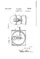
- Figure 1 1s a side view, partly in section.
- FIG. 2 is a top plan view.
- Figure 3 is a sectional 'ew on line 3-3 of Figure 1.
- Figure 4 is a sectional view on line 4-4 of Figure 1.
- Figure 5- is a sectional view on line 5-5 of Figure 1.
- the numeral 1 designates the combustion chamber which consists of a plurality of concentrically arranged tubular metallic sections 2 3 and 4, of conical formation, the major ends of which are united by flanges 5, said flanges being provided with openings 6 in,order that the 1928.
- annular chambers and 8 defined by the walls ofthe sections 2, 3 and 4 will be in communication.
- the sections are of truncated conical formation and have their major ends connected, the major diameter of the combustion chamber will be centrally located.
- the forward ends of the sections have fitted therein a ring 13 which supports the rear end of a nozzle 14, said nozzle being formed from any suitable refractory material, and being engaged in a protective ring 15.
- a plurality of rows of circularly alined nozzles 16 are threaded in the walls of the sections 2 and are alined with similarly arranged nozzles 17 threaded in the walls of the sections 3, the latter nozzles being extended for a short distance into the nozzles 16, as shown in Fig. 6. It will be observed that the nozzles are inclined in a direction toward the forward end of the combustion chamber 1.
- a carbureter 18 is provided and may be of any desired construction, said carbureter having'leading therefrom a fuel'conducting pipe 19 which communicates with the chamber 20, the inner wall of which is pro-- quizd by the closure plate 11, said plate haviug an opening 21 therein which opens into the compartment 8 in order that fuel from the'carbureter 18 can freely enter the compartment 8 for discharge through the nozzle 17.v Fuel is conducted to the carbureter 18 through the pipe line 22 which leads from a supply tank (not shown).
- a nozzle 23 Coaxial with the nozzle 14 is a nozzle 23 which is slidable in the sleeve 24:, said nozzle communicating with the housing 25 of the turbine 26 through the conduit 26, said turbine exhausting into the flared head 27 which closes the forward end of the air superheating drum 28, the hot exhaust gases passing through the tubes 29 mounted longitudinally within the drum, said tubes discharging into a head 30 which exhausts through the nozzle 31- to atmosphere.
- the turbine shaft 32 operates a compressor 33 of conventional form, the-fan blades ,34
- the shaft 38 drives a shaft 38 andinterposed between said shaft is a flexible connection 39 of well known construction.
- the shaft 38 is geared to the driving gear 40 fixed to the f shaft'41, which, in this instance, drives a propeller.
- the shaft 41 has a worm .42 upon 1ts rear end' for. driving the worm 43 the "latter worm driving a transverse shaft 44 which'drives a generator (not shown) and also the centrifugal governor 45 for a purpose to be hereinafter described.
- the s aft 32 rotates in a collar 49, the front face of which is formed with an annular rim 50 which defines an air chamber 51,- said ing in" order that air can be drawn thereinto. for furnishin the compressor with atmos'lpheric air.
- T a rim has. a plurality of s 'ots 52 adapted to cooperatewith the slots 53 formed in the band 54'which is rotatably engaged upon'the rim.
- An arm 55 is pivotally supported bye/bracket 55' and has its rear end pivotally connected to one end of a link .56, said link having its other end pivotally connected to the band 54, the'forward end of the arm 55 being connected with thegovernor- 45.
- the speed of the shaft- 44 varies the'governor' will 0 rate to rotate the ban whereupon the a ion of air 7 to the chamber .51 will be dontrolled.
- the compressor will force air to the drum-28 through the pipe 36 and around the pi es '29, the pipes being maintained hot byt he exhaust gases passin from the turbine.
- Part of the heated air W1 1 pass through-the pipe 39 to the carburetor 18, whereas the portion flowing through the band should the pipe 37 enters the j chamber 12.
- the air 4 entering thewchamber 8 will be mixed with fuel flowingfrom the carburetor which is too rich toignite until mixed with additional air.
- Thefuel discharging from the nozzle 17 will mix with air flowing into the chamber 7 tion in the combustion chamber 1.
- the ducts of combustion will be dischar ed rom the combustion chamber intothe tur ine 26 at increased volume and under constant pressure produced by vthe compressor 33.
- Y i v such that the employment of a refractory lining'is unnecessary, since thearrangement of the compartments'7 and Bare such that the sections will be maintained in a comparatively .0001 state andwill not be subjected to intense heat, thus prolonging the life of the combustion chamber.
- the nozzles areso arranged that the combustible fuel will be ejected toward the longitudinal axis of the combustion chamber.
- the unitsof the plant are preferably confined between side frames 66 which are so arranged that the parts of the of course, be understood that'other .means -may beused formounting the plant; *The mixture in the combustion chamber in igcplant will be I but it will,
- chargin means for effecting a mixture with the products of combustion 'andmeans conby the temperature of-the products of combustion for regulating the mixture of the additional supply of atmospheric air with the roducts of combustion flowing from the combustion chamber.
- a combustion chamber including outer and inner sections. and an intermedlate section, said sections being for mixing fuel and hirhha discharging a into the combustion chamber.
- a combustion chamber including concentrically arranged sections defining arr-annular fuel compartment and an annular air compartment, air nozzles carried by the sections forming the air compartment, fuel nozzles carried by the sections forming the fuel compartment, the air nozzles being entered by .thefueln'ozzles, a heater, means for forcing air through the heater and means for distributing the heated air to the fuel and.
- a combustion chamber consisting of a plurality of concentrically ar- 7 ranged sections defining annular fuel and air compartments, a discharge nozzle fitted in one end' of the combustion chamber, airim .fitted' in-the other end thereof and having-- ports therein communicating with the air chamber, a plate supported the and i communicating with buretor, means for conducting heated from the heater through the carburetor and openin' into the fuel compartment and throng the ports into'the air compartment, and means anording eommuication between We the air and fuel compartments for mixing the air and fuel for 4.
- arge into the combustion from the heater to the r one end of the combustion chamber, a rim fitted in the other end thereof, a spreader supported by the rim, said rim having a plurality of ports communicating with the a air compartment, a plate supported by therim and having openings therein communicating with 7 the fuel compartment, an air heater associated with the combu'stionchamber, a carburetor, means for conducting a portion of the air from the heater-into the carburetor and through the openings into the fuel compa'rtment, and a portion thereofthrough the ports into the air compartment, and means
Landscapes
- Engineering & Computer Science (AREA)
- Chemical & Material Sciences (AREA)
- Combustion & Propulsion (AREA)
- Mechanical Engineering (AREA)
- General Engineering & Computer Science (AREA)
- Spray-Type Burners (AREA)
Description
May 10, 1932.
R. E. LASLEY POWER PLANT Filed m 51, L928 4 Sheets-Sheet I. ab bangs l May 10, 1932. R. E. LASLEY 1,357,556
' rowan PLANT Filed May 31, 1928 LSheets-Sheet 2 I v M I v I fltto'amzui y I932. R. E. LASLEY 1,357,556 POWER PLANT I Filed May 31, 1928 4-Sheets-Sheet s R E. LASLEY May 10, 1932.
POWER PLANT I 'Filed'lday :51, 1928 4 Sh eets-Sheet 4 'IIIIIII I/IlI/III Swuemtoz RE.L a 5153' Patented May 10, 1932 UNITED STATES PATENT; o Fic- ROBERT EDLEY LASLEY,OF LIBERTYVILLE, ILLINOIS A POWER PLANT Application flied May 31,
The present invention is directed to improvements in power plants and is an improvement on my co-pending application, Serial No. 163,409, filed December*8, 1926.
The primary object of the invention is to provide a power plant including a combustion chamber constructed in a manner to eliminate the use of a'refractory lining, there by providing a combustion chamber which is extremely light, and, consequently, ad-
7 mirably adapted for use in connection with air craft.
Another object of the invention is to provide a power plant including a combustion chamber so constructed that air and fuel will be effectively mixed to produce a combustible fuel for introduction into the combustion chamber under pressure produced by a compressor in order that the products of combustion will be discharged from the combustion chamber at increasedvolume and at a constant pressure produced by the compressor. 4
Another object of the invention is to provide a power plant wherein air and fuel are compressed by a compressor in a heatedstate to provide a highly combustible mixture.
With these and other objects in view, this invention resides in the novel features of construction, formation, combination andarrangement of parts to be hereinafter more fully described, claimed and lllustrated ln the accompanyingdrawings, in which:
. Figure 1 1s a side view, partly in section.
v Figure 2 is a top plan view. .7 Figure 3 is a sectional 'ew on line 3-3 of Figure 1. Q
Figure 4 is a sectional view on line 4-4 of Figure 1. v
Figure 5-is a sectional view on line 5-5 of Figure 1. I Figure 6 is a sectional view on line 6-6 of Fiure'l eferring to the drawings, the numeral 1 designates the combustion chamber which consists of a plurality of concentrically arranged tubular metallic sections 2 3 and 4, of conical formation, the major ends of which are united by flanges 5, said flanges being provided with openings 6 in,order that the 1928. Serial No. 281,902.
annular chambers and 8 defined by the walls ofthe sections 2, 3 and 4 will be in communication. The sections are of truncated conical formation and have their major ends connected, the major diameter of the combustion chamber will be centrally located.
The minor ends of the sections arefitted in the ported rim 9, said rim having a conical spreader 10 carried thereby, and having .'aclosure plate 11 to provide a' chamber 12,
the purpose of which will later appear.
The forward ends of the sections have fitted therein a ring 13 which supports the rear end of a nozzle 14, said nozzle being formed from any suitable refractory material, and being engaged in a protective ring 15. A plurality of rows of circularly alined nozzles 16 are threaded in the walls of the sections 2 and are alined with similarly arranged nozzles 17 threaded in the walls of the sections 3, the latter nozzles being extended for a short distance into the nozzles 16, as shown in Fig. 6. It will be observed that the nozzles are inclined in a direction toward the forward end of the combustion chamber 1.
A carbureter 18 is provided and may be of any desired construction, said carbureter having'leading therefrom a fuel'conducting pipe 19 which communicates with the chamber 20, the inner wall of which is pro-- duced by the closure plate 11, said plate haviug an opening 21 therein which opens into the compartment 8 in order that fuel from the'carbureter 18 can freely enter the compartment 8 for discharge through the nozzle 17.v Fuel is conducted to the carbureter 18 through the pipe line 22 which leads from a supply tank (not shown). Coaxial with the nozzle 14 is a nozzle 23 which is slidable in the sleeve 24:, said nozzle communicating with the housing 25 of the turbine 26 through the conduit 26, said turbine exhausting into the flared head 27 which closes the forward end of the air superheating drum 28, the hot exhaust gases passing through the tubes 29 mounted longitudinally within the drum, said tubes discharging into a head 30 which exhausts through the nozzle 31- to atmosphere.
The turbine shaft 32 operates a compressor 33 of conventional form, the-fan blades ,34
thereof forcing air into the housing 35 and 'from thence to the pipe 36 -to the forward end of the drum 28 in order that fresh air induced by the compressor will be preheated by the heat radiated from the tubes 28. A-
through the pipe 39 which leads to the'carbureter 18 to carry fuel therefrom into the pipe 19 and into the compartment -8. The
' turbine drives a shaft 38 andinterposed between said shaft is a flexible connection 39 of well known construction. The shaft 38 is geared to the driving gear 40 fixed to the f shaft'41, which, in this instance, drives a propeller. The shaft 41 has a worm .42 upon 1ts rear end' for. driving the worm 43 the "latter worm driving a transverse shaft 44 which'drives a generator (not shown) and also the centrifugal governor 45 for a purpose to be hereinafter described. 1
In order to control the admissionof fresh air'into the :1 into the nozzle 23 from the combustion chamcut that the link 47 will control. the s11 chamber'opening into the compressor hous I her 1, the rear end of a link,46 is pivotall connected thereto, the-forward end of whic' is pivoted to one end of the bell crank lever 47, the other endof, the lever being connected to the thermostat 48. It will be thus a m movement of the nozzle 23 to re late th mixture of atmospheric airwith t e motive fluid passin from the combustion chamber 1 throu h t e nozzle 14. Y
The s aft 32 rotates in a collar 49, the front face of which is formed with an annular rim 50 which defines an air chamber 51,- said ing in" order that air can be drawn thereinto. for furnishin the compressor with atmos'lpheric air. T a rim has. a plurality of s 'ots 52 adapted to cooperatewith the slots 53 formed in the band 54'which is rotatably engaged upon'the rim. An arm 55 is pivotally supported bye/bracket 55' and has its rear end pivotally connected to one end of a link .56, said link having its other end pivotally connected to the band 54, the'forward end of the arm 55 being connected with thegovernor- 45. Obviously, when the speed of the shaft- 44 varies the'governor' will 0 rate to rotate the ban whereupon the a ion of air 7 to the chamber .51 will be dontrolled.
In the pipe 36, which conducts the air.
from the compressor to the drum 28, is -a pipe 57 which leads to the pressure re la- 59 connectedthereto for tor 5.8 of conventional form, which has a ever sliding the bar .60, being connected to line 22, while the the rear end of said bar the valve er in the fuel forward end of said bar is connected-to one arm of the bell crank lever 62. Theother";
products of combustion flowingeflectivelysupported {and house arm of the lever 62 has connected thereto I t the lower end of a link 63, said 'link having a slot 64 in-its upper end for engaging the stud 65 carried by the band 54. It will be thus seen that should the connection 39 be-' tween driving shaft 38 and shaft 32 breakandthe compressor race, the pressure in the pipe 36 will be increased, thus operating the Y not affect the movement of the band, this link only operating the compressor race. v4 To ignite the combustible mixture in the chamber 1, .the hot point 66=is' employed and extends through the walls'of the sections 2, 3 and 4.
In operation, the compressor will force air to the drum-28 through the pipe 36 and around the pi es '29, the pipes being maintained hot byt he exhaust gases passin from the turbine. Part of the heated air W1 1 pass through-the pipe 39 to the carburetor 18, whereas the portion flowing through the band should the pipe 37 enters the j chamber 12. The air 4 entering thewchamber 8 will be mixed with fuel flowingfrom the carburetor which is too rich toignite until mixed with additional air. Thefuel discharging from the nozzle 17 will mix with air flowing into the chamber 7 tion in the combustion chamber 1. The ducts of combustion will be dischar ed rom the combustion chamber intothe tur ine 26 at increased volume and under constant pressure produced by vthe compressor 33. The
from the chamber 12 for igniconstruction of the combustion chamber is Y i v such that the employment of a refractory lining'is unnecessary, since thearrangement of the compartments'7 and Bare such that the sections will be maintained in a comparatively .0001 state andwill not be subjected to intense heat, thus prolonging the life of the combustion chamber. Further, it will be observed that the nozzles areso arranged that the combustible fuel will be ejected toward the longitudinal axis of the combustion chamber. The unitsof the plant are preferably confined between side frames 66 which are so arranged that the parts of the of course, be understood that'other .means -may beused formounting the plant; *The mixture in the combustion chamber in igcplant will be I but it will,
nee-7,550
the products of combustion fromthe com ustion chamber, means for admitting an addi- .tional supply of atmospheric air to said dislnner section,
' ha. ing opemngs therein the fuel compartment, an air heater, a carj 40 air trolled chamber.
chargin means for effecting a mixture with the products of combustion 'andmeans conby the temperature of-the products of combustion for regulating the mixture of the additional supply of atmospheric air with the roducts of combustion flowing from the combustion chamber.
2. In combination, a combustion chamber including outer and inner sections. and an intermedlate section, said sections being for mixing fuel and hirhha discharging a into the combustion chamber.
5'. In combination, a combustion chamber including concentrically arranged sections defining arr-annular fuel compartment and an annular air compartment, air nozzles carried by the sections forming the air compartment, fuel nozzles carried by the sections forming the fuel compartment, the air nozzles being entered by .thefueln'ozzles, a heater, means for forcing air through the heater and means for distributing the heated air to the fuel and.
air compartments, the fuel-and air mixingm Y the combustion chamber.
the fuel and air'nozzles for discharge mto In-testimony whereof I afiix my signature,
ROBERT EDLEY LAS EY.
spaced to provide annular fuel and air comartments. Mixingfnozzles carried by the fuel nozzles carried by the intermediate section and 'extendiiiginto the mixing nozzles, a heater,1-a carburetor, means for conducting air air com artment and through-the carburetor to the uel compartment, the fuel and air being mixed in the mixing nozzles and dis charged into the combustion chamber.
3. In combination, a combustion chamber consisting of a plurality of concentrically ar- 7 ranged sections defining annular fuel and air compartments, a discharge nozzle fitted in one end' of the combustion chamber, airim .fitted' in-the other end thereof and having-- ports therein communicating with the air chamber, a plate supported the and i communicating with buretor, means for conducting heated from the heater through the carburetor and openin' into the fuel compartment and throng the ports into'the air compartment, and means anording eommuication between We the air and fuel compartments for mixing the air and fuel for 4. In combination, a combustionchamber compartments, a discharge nozzle fitted in.
arge into the combustion from the heater to the r one end of the combustion chamber, a rim fitted in the other end thereof, a spreader supported by the rim, said rim having a plurality of ports communicating with the a air compartment, a plate supported by therim and having openings therein communicating with 7 the fuel compartment, an air heater associated with the combu'stionchamber, a carburetor, means for conducting a portion of the air from the heater-into the carburetor and through the openings into the fuel compa'rtment, and a portion thereofthrough the ports into the air compartment, and means
Priority Applications (1)
| Application Number | Priority Date | Filing Date | Title |
|---|---|---|---|
| US281902A US1857556A (en) | 1928-05-31 | 1928-05-31 | Power plant |
Applications Claiming Priority (1)
| Application Number | Priority Date | Filing Date | Title |
|---|---|---|---|
| US281902A US1857556A (en) | 1928-05-31 | 1928-05-31 | Power plant |
Publications (1)
| Publication Number | Publication Date |
|---|---|
| US1857556A true US1857556A (en) | 1932-05-10 |
Family
ID=23079249
Family Applications (1)
| Application Number | Title | Priority Date | Filing Date |
|---|---|---|---|
| US281902A Expired - Lifetime US1857556A (en) | 1928-05-31 | 1928-05-31 | Power plant |
Country Status (1)
| Country | Link |
|---|---|
| US (1) | US1857556A (en) |
Cited By (9)
| Publication number | Priority date | Publication date | Assignee | Title |
|---|---|---|---|---|
| US2469679A (en) * | 1944-07-13 | 1949-05-10 | Edwin T Wyman | Gas turbine |
| US2502878A (en) * | 1943-02-23 | 1950-04-04 | Heat Pumps Ltd | Combustion products operated turbine |
| US2540665A (en) * | 1946-02-01 | 1951-02-06 | Daniel And Florence Guggenheim | Mechanism for coaxial feeding of two combustion liquids to a combustion chamber |
| US2597253A (en) * | 1945-11-13 | 1952-05-20 | Effie B Melchior | Jet-propulsion nozzle |
| US2609040A (en) * | 1950-03-14 | 1952-09-02 | Elliott Co | Combustion apparatus using compressed air |
| US2700415A (en) * | 1941-10-30 | 1955-01-25 | Power Jets Res & Dev Ltd | Liquid fuel supply system for aircraft combustion turbines |
| US2714286A (en) * | 1944-07-14 | 1955-08-02 | Aerojet General Co | Liquid propellant injection system for jet motors |
| US3614283A (en) * | 1966-06-27 | 1971-10-19 | Cabot Corp | High combustion rate burner |
| US4024702A (en) * | 1970-09-23 | 1977-05-24 | Perry David Hudson | Combustion products pressure generators continuous burner type and engines |
-
1928
- 1928-05-31 US US281902A patent/US1857556A/en not_active Expired - Lifetime
Cited By (9)
| Publication number | Priority date | Publication date | Assignee | Title |
|---|---|---|---|---|
| US2700415A (en) * | 1941-10-30 | 1955-01-25 | Power Jets Res & Dev Ltd | Liquid fuel supply system for aircraft combustion turbines |
| US2502878A (en) * | 1943-02-23 | 1950-04-04 | Heat Pumps Ltd | Combustion products operated turbine |
| US2469679A (en) * | 1944-07-13 | 1949-05-10 | Edwin T Wyman | Gas turbine |
| US2714286A (en) * | 1944-07-14 | 1955-08-02 | Aerojet General Co | Liquid propellant injection system for jet motors |
| US2597253A (en) * | 1945-11-13 | 1952-05-20 | Effie B Melchior | Jet-propulsion nozzle |
| US2540665A (en) * | 1946-02-01 | 1951-02-06 | Daniel And Florence Guggenheim | Mechanism for coaxial feeding of two combustion liquids to a combustion chamber |
| US2609040A (en) * | 1950-03-14 | 1952-09-02 | Elliott Co | Combustion apparatus using compressed air |
| US3614283A (en) * | 1966-06-27 | 1971-10-19 | Cabot Corp | High combustion rate burner |
| US4024702A (en) * | 1970-09-23 | 1977-05-24 | Perry David Hudson | Combustion products pressure generators continuous burner type and engines |
Similar Documents
| Publication | Publication Date | Title |
|---|---|---|
| US3691762A (en) | Carbureted reactor combustion system for gas turbine engine | |
| US3925002A (en) | Air preheating combustion apparatus | |
| US2628475A (en) | Jet combustion device embodying pretreatment of fuel before combustion | |
| US2592938A (en) | Jet engine with compressor driven by rotating jets which exhaust into thrust augmenting duct | |
| US2508420A (en) | Combustion apparatus | |
| US3747336A (en) | Steam injection system for a gas turbine | |
| US2798360A (en) | Ducted fan type jet propulsion engine | |
| US2447482A (en) | Turbine apparatus | |
| US2479776A (en) | Turbo-jet power plant with fuel vaporizer for afterburners | |
| US2469679A (en) | Gas turbine | |
| NO132165B (en) | ||
| US1857556A (en) | Power plant | |
| US2195025A (en) | Gas turbine | |
| US1854615A (en) | Power plant | |
| US2046767A (en) | Combustion apparatus | |
| US2074098A (en) | Rocket airship | |
| US2482394A (en) | Gas turbine | |
| US2636344A (en) | Internal-combustion turbine with self-cooling vanes | |
| JPS5824694B2 (en) | gas turbines | |
| US2632299A (en) | Precombustion chamber | |
| US3153323A (en) | Internal combustion apparatus | |
| US2715436A (en) | Resonant pulse jet combustion heating device | |
| US2637974A (en) | Combustion apparatus for an air stream and propulsive system | |
| GB1028296A (en) | Improvements in or relating to by-pass turbojets | |
| US1532041A (en) | Pulverized-fuel burner |