US1857554A - Coffee percolator and the like - Google Patents
Coffee percolator and the like Download PDFInfo
- Publication number
- US1857554A US1857554A US394526A US39452629A US1857554A US 1857554 A US1857554 A US 1857554A US 394526 A US394526 A US 394526A US 39452629 A US39452629 A US 39452629A US 1857554 A US1857554 A US 1857554A
- Authority
- US
- United States
- Prior art keywords
- pot
- chamber
- passage
- wall
- skirt
- Prior art date
- Legal status (The legal status is an assumption and is not a legal conclusion. Google has not performed a legal analysis and makes no representation as to the accuracy of the status listed.)
- Expired - Lifetime
Links
- 238000010438 heat treatment Methods 0.000 description 14
- 230000008016 vaporization Effects 0.000 description 14
- 238000010276 construction Methods 0.000 description 8
- XLYOFNOQVPJJNP-UHFFFAOYSA-N water Substances O XLYOFNOQVPJJNP-UHFFFAOYSA-N 0.000 description 7
- 239000007788 liquid Substances 0.000 description 4
- 230000009191 jumping Effects 0.000 description 2
- 101100402341 Caenorhabditis elegans mpk-1 gene Proteins 0.000 description 1
- 239000012530 fluid Substances 0.000 description 1
- 230000005484 gravity Effects 0.000 description 1
- 238000004519 manufacturing process Methods 0.000 description 1
- 239000000463 material Substances 0.000 description 1
- 230000000284 resting effect Effects 0.000 description 1
Images
Classifications
-
- A—HUMAN NECESSITIES
- A47—FURNITURE; DOMESTIC ARTICLES OR APPLIANCES; COFFEE MILLS; SPICE MILLS; SUCTION CLEANERS IN GENERAL
- A47J—KITCHEN EQUIPMENT; COFFEE MILLS; SPICE MILLS; APPARATUS FOR MAKING BEVERAGES
- A47J31/00—Apparatus for making beverages
- A47J31/04—Coffee-making apparatus with rising pipes
- A47J31/053—Coffee-making apparatus with rising pipes with repeated circulation of the extract through the filter
Definitions
- This invention relates toximprovements in coflee percolators and the like, and has as its aim to provide an improved arrangement by means-of which the liquid is caused to circulate more; orless positively and in a continnous uniform stream through the vaporizing or'heating chamber and the, fountain tube.
- my improved arrangement is such that the passage leading from the pct to the vaporizing chamber is of unvarying size at times irrespective of the jumping or movement of parts of the pump under'the impulses with which the fluid. is forced through the fountain tube.
- a further aim of the invention is to provide an improved arrangement wherein the liquid is eilectivelyand rapidly heated to the desired temperature as it passes into and through-the vaporizing chamber.
- Another object of the invention is to provide'an arrangement of this sort which is characterized by its extreme simplicity in construction, its economy in manufacture, and the ease and facility with which the parts may be kept a clean and sanitary condition.”
- Fig. 2 is a top view of the member which formsthe top of the heating chamber.
- detaihA designates a vessel .or pot "of any suitable be indicated in the appended.
- C designates a fountain tube which leads from the vaporizing chamber, hereinafter described more in detail, and discharges to the interior of a dome D.
- E is the usual perforated receptacle or tray located in the upper end of the pot and adapted to contain the material, such as coffee, onto which the liquid is sprayed and through which the liquid seeps back into the pot.
- the arrangement so. far described is an old and well-known one and, therefore, these parts are shown more or less diagrammatically and for purposes of illustration only,'as the particular construction thereof forms no part of thepresent invention;.
- the percola-tor may be heated in any able manner, but byway of'ilhistr'ation have "shown an electrical'heating unit F for thisv purpose.
- the specific construction of this heating unit is not :shown as, obviously,
- this heating unit is located in a recess provided in the bottom of the pot or bowl A by forming araised central bosshav ing a circumferential wall 10 and a top wall 11'.
- theheating unit is in direct heat contacting relation to the walls 10 and 11.7 Thetopwall 11 forms the bottom of thevaporizing'chamber.
- Theheating unit l may be secured in place in any suitable man- 3 ner,-asby means of bolts 12, the heads 13 of which serve to hold the upper member of the chamber in spacedrelationto the lower member 11.
- the upper wall ofthe heating chamber 14 is formed by a member 15 having a central opening in which the lower end of the fountain tube G is secured.
- This member 15 is in the form of a round base havingia central dome-shaped portion 16, and a cincumferential skirt 17 which surrounds the boss in which the heating unit is located.
- the internal diameter of the skirt 17 is slightly larger than the diameter of thewall 10 so as to leave an entrance passage 19 between these mem bers.
- This entrance passage is generally of annular form and is substantially of uniform size or width throughout its height so that, irrespective of the position of the skirt with respect to the wall, the size of the en trance passage is always the same.
- the operation of the device is briefly as follows: The pot having been filled with water tothe desired level, and the coffee having beenplaced withinthe receptacle E, the cur rent is turned on the heating unit F.
- the heat generated raises the temperature of the water within the heating chamber 14:, caus ing the heated water to flowupwardly through the fountain tube C in a manner well understood.
- water is forced out of the chamber 14 through the tube C, water is drawn into the heating chamber through the passage 19 from the bottom of the pot. As this water flows through the passage 19, its'temperature is raised and when it reaches the chamber 14, its temperature is further raised to a degree which will cause it to flow through the tube C.
- the entrance passage 19 does not vary in size so that the flow of water through that passage is not affected by the jumping action, which means that a more uniform and positive operation is obtained. It willbe observed that my improved arrangement is extremely simple; the useof gravity valves and the like being eliminated. There is nothing to get out of order. The bottom of the pot and all parts of the pump are readily accessible so that theylcan be kept in sanitary condition.
- a pot having a fixed member in its bottom, means for heating. said member,a movable member above said fixed'member and forming therewith a vaporizing chamber, a fountain tube carried by said'movable'member and leading from said vaporizing chamber, and, an entrance passage between said fixed member and movable member leading upwardly to said vaporizing chamber, said passage having an effective area which remains constant during movement of the movable member.
- a pot having a fixed vertical circumferential wall inits bottom and a Wall adapted to form the bottom of a vaporizing chamber, a member spaced from said last mentioned wall and forming therewith a vaporizing chamber, and a fountain tube carried by said member and leading from said chamber, saidmemvber having a depending circumferential skirt encircling, spaced from and parallel to said circumferential wall so as to form therewith an entrance passage to said vaporizing chamber of uniform size, the receiving end of said passage being in unrestricted and uniform communication with the interior of said pot in all positions of said member.
- I11 a percolator or the like, a pot ha ing a raised boss in its bottom'providing a verticalcircumferential wall and atop wall, a heating element within said boss,'a movable member over said top wall and forming therewith a vaporizing chamber, and a fountain tube leading from said chamber, said member having a vertical. depending skirt surrounding said, boss, said skirt and member defining a passage the effective area of which remains constant during movement of thesaid movable member, the lowerend of said skirt being spaced from the bottom of said pot a distance at least as great asth'at between said skirt'and said circumferential wall.
- a pot having a raised boss in its bottom forming a vertical circumferential wall and a top wall, a heating unit within said boss, bolts'for securing said heating unit in place andliaving their heads extending above said upper wall, a
- dome-shaped member resting upon the heads of said bolts and forming with said upper wall a vaporizing chamber, and a fountain tube leading from said chamber, said member having a circumferential skirt parallel. to, spaced from and surrounding saidcircuniferential wall and forming therewith an entrance passage of uniform size throughout itsheight, the end of said skirt being spaced from the bottom of said pot a distance at a passage the effective area of which remains I unchanged during movements of the domeshaped member.
- a pot having a a a fixed surface portion adapted to be heated, and a movable member cooperatively disposed with respect to the fixed surface portion to provide a vaporizing chamber and an unvalved entrance passage leading from the pot into the vaporizing chamber, said sur- 1 face portion and said movable member being so interfitted as to maintain said entrance passage of unvarying size in all positions of said movable member.
Landscapes
- Engineering & Computer Science (AREA)
- Food Science & Technology (AREA)
- Apparatus For Making Beverages (AREA)
Description
May 10, 1932. J. F. LAMB COFFEE PERCOLATOR AND THE LIKE Filed Sept. 23,. 1929 gvvvento'o Patented May 10, 1932 5,4.
UNITED STA P T rof ncgA Josnrn F. Lama-or new BRITAIN, couuncmreu'r, Assienoa ro LAnnEns, FRARY & CLARK, on NEW BRITAIN; CONNECTICUT, A ooaronnriouor 'gonnncric or ,1
. some rEncoLATon AND mm Application filed September 23, 1929. Serial No. 394,526.
a This inventionrelates toximprovements in coflee percolators and the like, and has as its aim to provide an improved arrangement by means-of which the liquid is caused to circulate more; orless positively and in a continnous uniform stream through the vaporizing or'heating chamber and the, fountain tube.
To end, my improved arrangement is such that the passage leading from the pct to the vaporizing chamber is of unvarying size at times irrespective of the jumping or movement of parts of the pump under'the impulses with which the fluid. is forced through the fountain tube.
A further aim of the invention is to provide an improved arrangement wherein the liquid is eilectivelyand rapidly heated to the desired temperature as it passes into and through-the vaporizing chamber.
Another object of the invention is to provide'an arrangement of this sort which is characterized by its extreme simplicity in construction, its economy in manufacture, and the ease and facility with which the parts may be kept a clean and sanitary condition."
Qther objects will be in part obvious and in part pointed out more in detail hereinafter.
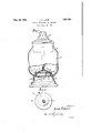
The invention accordingly consists in the features of construction, combination of elements andarrangement of parts which will be exemplified in the construction hereinafter set forth and the scope of the application of which will In the accompanying drawings, wherein I have shown, for illustrative purposes, one embodiment which the present invention may take: V v a Figure l'is an elevational view, with parts 40 in section, of a percolatorin which my improvements are incorporated; and
Fig. 2is a top view of the member which formsthe top of the heating chamber.
Referring to the drawings in, detaihA designates a vessel .or pot "of any suitable be indicated in the appended.
shape or construction located on a base B.
C designates a fountain tube which leads from the vaporizing chamber, hereinafter described more in detail, and discharges to the interior of a dome D. E is the usual perforated receptacle or tray located in the upper end of the pot and adapted to contain the material, such as coffee, onto which the liquid is sprayed and through which the liquid seeps back into the pot. The arrangement so. far described is an old and well-known one and, therefore, these parts are shown more or less diagrammatically and for purposes of illustration only,'as the particular construction thereof forms no part of thepresent invention;.
The percola-tor may be heated in any able manner, but byway of'ilhistr'ation have "shown an electrical'heating unit F for thisv purpose. The specific construction of this heating unit is not :shown as, obviously,
it may be varied as desired. For exampla it may be of a construction similar-to that shown in my Patent No. 1,060,264 granted April 29th, 1913; In the present illustrative disclosure, this heating unit is located in a recess provided in the bottom of the pot or bowl A by forming araised central bosshav ing a circumferential wall 10 and a top wall 11'. By preference, theheating unit is in direct heat contacting relation to the walls 10 and 11.7 Thetopwall 11 forms the bottom of thevaporizing'chamber. Theheating unit l may be secured in place in any suitable man- 3 ner,-asby means of bolts 12, the heads 13 of which serve to hold the upper member of the chamber in spacedrelationto the lower member 11.
In accordance with the present invention,
the upper wall ofthe heating chamber 14 is formed by a member 15 having a central opening in which the lower end of the fountain tube G is secured. This member 15 is in the form of a round base havingia central dome-shaped portion 16, and a cincumferential skirt 17 which surrounds the boss in which the heating unit is located. The internal diameter of the skirt 17 is slightly larger than the diameter of thewall 10 so as to leave an entrance passage 19 between these mem bers. This entrance passage is generally of annular form and is substantially of uniform size or width throughout its height so that, irrespective of the position of the skirt with respect to the wall, the size of the en trance passage is always the same.-
The operation of the device is briefly as follows: The pot having been filled with water tothe desired level, and the coffee having beenplaced withinthe receptacle E, the cur rent is turned on the heating unit F. The heat generated raises the temperature of the water within the heating chamber 14:, caus ing the heated water to flowupwardly through the fountain tube C in a manner well understood. As the water is forced out of the chamber 14 through the tube C, water is drawn into the heating chamber through the passage 19 from the bottom of the pot. As this water flows through the passage 19, its'temperature is raised and when it reaches the chamber 14, its temperature is further raised to a degree which will cause it to flow through the tube C. Although the pump may jump afterthe percolator has been in operation, the entrance passage 19 does not vary in size so that the flow of water through that passage is not affected by the jumping action, which means that a more uniform and positive operation is obtained. It willbe observed that my improved arrangement is extremely simple; the useof gravity valves and the like being eliminated. There is nothing to get out of order. The bottom of the pot and all parts of the pump are readily accessible so that theylcan be kept in sanitary condition.
As many changes could be made in the above construction and many apparently 'widely difierent'embodiments of this invention could be made without departing from the scope thereof, it isintended that all matter contained in the above description or shown in the accompanyingdrawings shall be interpreted as illustrative and not in a limiting sense.
It is alsoto be understood that the language used inthe following claims is intended to cover all of the generic and specific features of the invention herein described and all statements of the scope of the invention which, as a matter of language, might be said to fall therebetween.
I claim as my'invention:
' I. In 'a percolator or the like, a pot having a fixed member in its bottom, means for heating. said member,a movable member above said fixed'member and forming therewith a vaporizing chamber, a fountain tube carried by said'movable'member and leading from said vaporizing chamber, and, an entrance passage between said fixed member and movable member leading upwardly to said vaporizing chamber, said passage having an effective area which remains constant during movement of the movable member.
2. In a percolator or the like, a pot having a fixed vertical circumferential wall inits bottom and a Wall adapted to form the bottom of a vaporizing chamber, a member spaced from said last mentioned wall and forming therewith a vaporizing chamber, and a fountain tube carried by said member and leading from said chamber, saidmemvber having a depending circumferential skirt encircling, spaced from and parallel to said circumferential wall so as to form therewith an entrance passage to said vaporizing chamber of uniform size, the receiving end of said passage being in unrestricted and uniform communication with the interior of said pot in all positions of said member.
3. I11 a percolator or the like, a pot ha ing a raised boss in its bottom'providing a verticalcircumferential wall and atop wall, a heating element within said boss,'a movable member over said top wall and forming therewith a vaporizing chamber, and a fountain tube leading from said chamber, said member having a vertical. depending skirt surrounding said, boss, said skirt and member defining a passage the effective area of which remains constant during movement of thesaid movable member, the lowerend of said skirt being spaced from the bottom of said pot a distance at least as great asth'at between said skirt'and said circumferential wall.
4. In a percolator or the like, a pot having a raised boss in its bottom forming a vertical circumferential wall and a top wall, a heating unit within said boss, bolts'for securing said heating unit in place andliaving their heads extending above said upper wall, a
dome-shaped member resting upon the heads of said bolts and forming with said upper wall a vaporizing chamber, and a fountain tube leading from said chamber, said member having a circumferential skirt parallel. to, spaced from and surrounding saidcircuniferential wall and forming therewith an entrance passage of uniform size throughout itsheight, the end of said skirt being spaced from the bottom of said pot a distance at a passage the effective area of which remains I unchanged during movements of the domeshaped member.
6. In a percolator or the like, a pot having a a a fixed surface portion adapted to be heated, and a movable member cooperatively disposed with respect to the fixed surface portion to provide a vaporizing chamber and an unvalved entrance passage leading from the pot into the vaporizing chamber, said sur- 1 face portion and said movable member being so interfitted as to maintain said entrance passage of unvarying size in all positions of said movable member.
JOSEPH F. LAMB.
Priority Applications (1)
| Application Number | Priority Date | Filing Date | Title |
|---|---|---|---|
| US394526A US1857554A (en) | 1929-09-23 | 1929-09-23 | Coffee percolator and the like |
Applications Claiming Priority (1)
| Application Number | Priority Date | Filing Date | Title |
|---|---|---|---|
| US394526A US1857554A (en) | 1929-09-23 | 1929-09-23 | Coffee percolator and the like |
Publications (1)
| Publication Number | Publication Date |
|---|---|
| US1857554A true US1857554A (en) | 1932-05-10 |
Family
ID=23559322
Family Applications (1)
| Application Number | Title | Priority Date | Filing Date |
|---|---|---|---|
| US394526A Expired - Lifetime US1857554A (en) | 1929-09-23 | 1929-09-23 | Coffee percolator and the like |
Country Status (1)
| Country | Link |
|---|---|
| US (1) | US1857554A (en) |
-
1929
- 1929-09-23 US US394526A patent/US1857554A/en not_active Expired - Lifetime
Similar Documents
| Publication | Publication Date | Title |
|---|---|---|
| US2663115A (en) | Aerated minnow bucket | |
| US2338072A (en) | Poultry waterer | |
| US2550902A (en) | Coffee-steeping device | |
| US2926594A (en) | Infusion devices | |
| US1857554A (en) | Coffee percolator and the like | |
| US2304004A (en) | Coffee maker | |
| US865776A (en) | Coffee-pot. | |
| US2323468A (en) | Teapot | |
| US1167775A (en) | Percolator. | |
| US133681A (en) | Improvement in coffee-pots | |
| US2164881A (en) | Vaporizer | |
| US1546434A (en) | Individual instant-coffee producer | |
| US2359936A (en) | Drip coffee maker | |
| US1453378A (en) | Steam ring | |
| US1920268A (en) | Metal coffee receptacle | |
| US2111777A (en) | Coffee maker | |
| US780851A (en) | Combined distiller and cooker. | |
| US1700614A (en) | Roaster | |
| US846473A (en) | Coffee-pot. | |
| US783525A (en) | Coffee-pot. | |
| US1439204A (en) | Condensing steamer | |
| US1452256A (en) | Percolator | |
| US1007999A (en) | Steam-cooker. | |
| US2449513A (en) | Soap feeder | |
| US3151737A (en) | Soap feeder |