US1857550A - Litter remover - Google Patents
Litter remover Download PDFInfo
- Publication number
- US1857550A US1857550A US388173A US38817329A US1857550A US 1857550 A US1857550 A US 1857550A US 388173 A US388173 A US 388173A US 38817329 A US38817329 A US 38817329A US 1857550 A US1857550 A US 1857550A
- Authority
- US
- United States
- Prior art keywords
- conveyor
- shaft
- litter
- sprocket
- elevator
- Prior art date
- Legal status (The legal status is an assumption and is not a legal conclusion. Google has not performed a legal analysis and makes no representation as to the accuracy of the status listed.)
- Expired - Lifetime
Links
Images


Classifications
-
- A—HUMAN NECESSITIES
- A01—AGRICULTURE; FORESTRY; ANIMAL HUSBANDRY; HUNTING; TRAPPING; FISHING
- A01K—ANIMAL HUSBANDRY; AVICULTURE; APICULTURE; PISCICULTURE; FISHING; REARING OR BREEDING ANIMALS, NOT OTHERWISE PROVIDED FOR; NEW BREEDS OF ANIMALS
- A01K1/00—Housing animals; Equipment therefor
- A01K1/01—Removal of dung or urine ; Removal of manure from stables
- A01K1/0135—Removal of dung or urine ; Removal of manure from stables by means of conveyor belts
Definitions
- This invention relates to stable litter cleaning devices and,particularlyto'.those devices wherein a conveyor 'me'mber is mechanically operated in a trough at the rear of cattle Stalls.
- a still 'further object of the invention is to provide an improved “means "for guiding V the material tromthe'cionveyoronto the elevator.
- V 39 A still further object 'dfthe'invention is to provide anj improved combination of elements wherein a drag c'onveyorlis operated in 'com-.
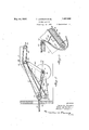
- FIG. 1 Referring-ito-the drawings wherein an em bodiment of the inventionlis illustrated igure 1 is' a -de13ai1- Crosssection-of -/a-.barn showing 1 my in'vention installed therein; certain ef the "details of the l invention tbeing omitted.
- V Figure '2 is -a side *view of my invention showing the working parts enlarged.
- Figure' 3 is-an enlarged detail view showing'the "guide for the cleaning conveyor with 60 the conveyor in contact therewith. t
- Figure 4 is a plan view of the invention.
- Figures 5 6, 7 and 8 are views ofsome 'of the details of construction.
- the numeral 10 designates the spaces for the cattle stalls, '1-1 the floor line and 12 the bottoin'oit' the litter gutter in which-the conveyor of ourinvention is installed.
- a pulley 22 is freely rotatable on-the shaft 1%.
- a clutch member 22 is pivotally secured on the-shaft le-to revolvetherewith and'has hearing pads 22222 which engage the side. 7
- the cleaning conveyor comprises two chains 25 and-flights "25 which connect the chains together.
- This chain*2'5 'attheend opposite tothat connected to the cablefll-y passes-over two sproeketwheeis '26-wliich are keyed to the shaftl l.
- V conveyor 25 passes over guidesl 27 which are secured to the elevator frame 1'3. These guides are curvedin s-u'clr'a Way as to -receive the conveyor 25'w1thout shock and' -lead the same around thelodeckd ofthe elevator to lead theconveyor to a'takei'p druni28.
- the take-uptlruinES is supported from-the elevator frame 13 by means of hangers 28 28 Mounted on the shaft 14 is a sprocket wheel 30.
- This sprocket wheel drives a chain 31 which in turnv drives a sprocket wheel 32, mounted on the shaft 33.
- the elevator chains 35 have connecting flights 36 which move over the floor 3? of the elevator and carry the material to the upper portion thereof. The upper outer portion of the ele-.
- Vator 35 extends at an angle to the main portion, this angle being such as to be substantially level when the elevator is inposition to discharge upon the manure spreaderor wagon used to carry off the litter.
- the chains 35 engage at theouter end of the elevator, the sprockets 37 which are secured to the shaft 38, the; shaft 38 is driven by the sprocket 39, which in turn, is driven by the chain 40 which is connected to a sprocket 41 on the shaft 33 already described. 'Mounted as idlers below the shaft 33', are the sprockets 42. These sprockets 42 carry the lower reach of the elevated chains 35.
- the take-up drum 28 is supported freely on the shaft 43.
- a pivoted clutch member 44 as at 45.
- This clutch member 44 is so mounted on its pivot 45 that it may swing in a plane, passing through the axis of the shaft 43 and which is perpendicular to the axis 45.
- A. clutch member 44 is in the shape of a double arm.
- the pad carrying a pad 46 and a pad 47.
- the clutch arm 44 is operated by the knurled knob 49.
- the pressure of the pad 47 and the pad 46 against the face of the sprocket wheel 50 may be absolutely controlled.
- the amount of pressure between the sprocket wheel 50 andthe pads 46 and 47 will determine the amount of torque which will be necessary to apply to the shaft 43 without causing the pads 46 and 47' to slip.
- the sprocket wheel 50 is mounted to freely rotate upon the shaft 43 when the clutch pads 46 and 47 are not in engagement withits side wall. Rotary motion is therefore transmitted from the shaft 43 to the sprocket wheel :50 by means of the pads 46 and 47 I
- Thesprocket 50 is connected by a crossed chain 51 to a sprocket 52 which is -mounted for rotation with the shaft 14.
- the motor 21 is started. Motion is transmitted through the belt 20, the pulley 19, the shaft 18, the sprocket 17, the sprocket chains 16, The clutch 22 is set so that it will not operate. This is brought about by unscrewingthe screw 22 which carries the pad 22*.
- This turning of the shaft 43 turns the drum '28 and takes up any slack in the conveyor 25 after the same has left the guide 27.
- the handle 22 is operated to tighten the clutch mem ber 22 to drive the drum 22.
- the cable 24 will be wound upon the drum 22 from which it was unwound as the conveyor 25 permitted its operative function. This taking up on the cable 24 causes the conveyor 25 to return to its original position.
- hinge members 58 are now grasped by the hand and the curved plates 57 are moved from the sprockets 26. The chain will now drop down on the sprockets 26 and be ready for another operation.
- a litter cleaning device comprising a litter conveyor
- an elevator frame adjacent the'delivery end of the conveyor and having its lower end at a lower level than the delivery end of the conveyor, a take-up drum for receiving the conveyor and supported by the elevator frame and a guide for the conveyor for guiding the conveyor from its delivery end to the take-up drum.
- a litter cleaning device comprising a litter conveyor, a pivoted elevator frame adjacent the delivery end of the conveyor and having its lower end at a lower level than the delivery end of the conveyor, a take-up drum for receiving the conveyor andsupported by the elevator frame, a drive-shaft for the conveyor, located at and supporting and driving its delivery end, and a pivot for the elevator, located substantially about the axis of the conveyor drive shaft.
- a litter cleaning device comprising a litter conveyor, a take-up drum for the conveyor, a shaft at and supporting the delivery end of the conveyor for positively driving the conveyor during operation, an elevator pivoted to swing about the axis of the shaft and carrying the take-up drum, rotary gripping means on the shaft for exerting a pulling action on the conveyor during its operation and a guide for receiving the conveyor from the gripping means, regardless of the pivoted position of the elevator.
- a litter cleaning device comprising a litter conveyor, a positively driven shaft at and supporting the delivery end of the conveyor to positively drive the same during operation,
- a litter cleaning device comprising a litter conveyor, a positively driven shaft at and supporting the delivery end of the conveyor to positively drive the same during operation, an elevator frame having its lower end adjacent the delivery end of the conveyor, a take-up drum to receive the conveyor after it has reached its delivery end, the take-up drum being supported on the elevator frame and a yielding drive means between the shaft and the take-up drum.
- a litter cleaning device comprising a litter conveyor connected at one end to a take-up drum and at its other end toa pullback cable, the pull-back cable being connected to a winding drum, the winding drum material guide pivoted on the elevator frame adjacent the delivery end of the conveyor and having its free end on the elevator.
Landscapes
- Life Sciences & Earth Sciences (AREA)
- Environmental Sciences (AREA)
- Zoology (AREA)
- Animal Husbandry (AREA)
- Biodiversity & Conservation Biology (AREA)
- Intermediate Stations On Conveyors (AREA)
Description
'F. JOHNSON ET AL 1,857,550
LITTER REMOVER Filed Aug. 24, 1929 5 Sheets-Sheet l f 3 65 WW ud HWE P R m u a a 2 Ffi May 10, 1932.
May 10, 1932.
F. JOHNSON ET AL LITTER REMOVER Filed Aug. 24, 1929 5 Sheets-Sheet 2 May 10, 1932. F. JOHNSON ET AL LITTER REMOVER Filed Aug. 24, 1929 5 Sheets- Sheet 3 M RM Patented May 10, '1932 UNITED} stares eerie s ie-iee amnnson, mam WiJ'OHNSON, Ann ARTHUR F. JOHNSOILQF mT'rLE ermine,
' I MINNESOTA I LITTER REMQVER Application filedAugust 24-, 1929. serial No. 388,173.
This invention relates to stable litter cleaning devices and,particularlyto'.those devices wherein a conveyor 'me'mber is mechanically operated in a trough at the rear of cattle Stalls.
' "In the construction of litter cleaningde" vices, it has been found to bedesirable to have such a constnuctionthat will permit of installation with very few changes -in the m construction-of the barn,
As'the space around a barn is always utilizedto a full a'dvaiitagepithas been ifoundto' provide an improvedi'm'eajns oftaking'up the.
conveyor after it h'a's delivered its "material 1 to 'the elevator.
A still 'further object of the invention is to provide an improved "means "for guiding V the material tromthe'cionveyoronto the elevator. V 39 A still further object 'dfthe'invention is to provide anj improved combination of elements wherein a drag c'onveyorlis operated in 'com-.
bination with an-leva'tor which may .be swung into a verticaljpositi'on. I
Other and further ets 'off'the invention will 3 be apparent to those skilled "in the i art from a reading-of the complete specification andlcl-aims.
Referring-ito-the drawings wherein an em bodiment of the inventionlis illustrated igure 1 is' a -de13ai1- Crosssection-of -/a-.barn showing 1 my in'vention installed therein; certain ef the "details of the l invention tbeing omitted. V Figure '2 is -a side *view of my invention showing the working parts enlarged.
Figure' 3is-an enlarged detail view showing'the "guide for the cleaning conveyor with 60 the conveyor in contact therewith. t
Figure 4 is a plan view of the invention. Figures 5 6, 7 and 8 are views ofsome 'of the details of construction.
The numeral 10 designates the spaces for the cattle stalls, '1-1 the floor line and 12 the bottoin'oit' the litter gutter in which-the conveyor of ourinvention is installed.
'lnthis inventionyparticular attention has been paid to theease-of installation already constructed. v
In the drawings it will be notedfthat acon veyor frame '13 is pivoted about itsa-Xes on;
the shaft 14'. This shaft Misdriventhrbug'h' a sprocket 15 thereon; which sprocket is driven by a chain 16. The'cha-in '16 is driven by a sprocket 17 mounted on a shaft *18zwhichis suitably driven'by a pulleyl9jfronna belt connection 20 to the motor 21.
A pulley 22 is freely rotatable on-the shaft 1%. A clutch member 22 is pivotally secured on the-shaft le-to revolvetherewith and'has hearing pads 22222 which engage the side. 7
surface of the pulley. The-thumb screw=-22 is provided and is threaded *the clutch member 22" and carries the pad-22 hen the threaded uneniber '22 5 is turned *to push the pad 22 invvardly, the clutch member 22' being pivoted to the shaft lepby pin 22,
perpendicular to its axis, 't'he t wo pads 22*,
on the surface o'fithe pulley 22.
22* will be caused to eXert-anequal pressure- This pulley carries one endo'l a-cableIQ L SO I which by suitable pulleys extends 1 overhead to the far end of the gutter12 and passes over suitable pulleys and is connected to the far end of the cleaningconveyon25.
The cleaning conveyor comprises two chains 25 and-flights "25 which connect the chains together. This chain*2'5 'attheend opposite tothat connected to the cablefll-y passes-over two sproeketwheeis '26-wliich are keyed to the shaftl l.
After passingpver the sprockets 26, the
*The take-uptlruinES is supported from-the elevator frame 13 by means of hangers 28 28 Mounted on the shaft 14 is a sprocket wheel 30. This sprocket wheel drives a chain 31 which in turnv drives a sprocket wheel 32, mounted on the shaft 33.. The elevator chains 35 have connecting flights 36 which move over the floor 3? of the elevator and carry the material to the upper portion thereof. The upper outer portion of the ele-.
Vator 35 extends at an angle to the main portion, this angle being such as to be substantially level when the elevator is inposition to discharge upon the manure spreaderor wagon used to carry off the litter.
The chains 35 engage at theouter end of the elevator, the sprockets 37 which are secured to the shaft 38, the; shaft 38 is driven by the sprocket 39, which in turn, is driven by the chain 40 which is connected to a sprocket 41 on the shaft 33 already described. 'Mounted as idlers below the shaft 33', are the sprockets 42. These sprockets 42 carry the lower reach of the elevated chains 35.
The take-up drum 28 is supported freely on the shaft 43. To this shaft 43 is secured a pivoted clutch member 44 as at 45. This clutch member 44 is so mounted on its pivot 45 that it may swing in a plane, passing through the axis of the shaft 43 and which is perpendicular to the axis 45. A. clutch member 44 is in the shape of a double arm.
The pad carrying a pad 46 and a pad 47.
, 47 is mounted'on a screw threaded shank 48 the sprocket 15 and the shaft 14.
which is screw threaded in the end of the.
We will now describe the operation: As-
suming that the parts are in such a position that the litter carrying conveyor 25 extends the whole length of the gutter 12. The motor 21 is started. Motion is transmitted through the belt 20, the pulley 19, the shaft 18, the sprocket 17, the sprocket chains 16, The clutch 22 is set so that it will not operate. This is brought about by unscrewingthe screw 22 which carries the pad 22*.
vets 37., and
The turning of this shaft 14 turns the sprockets 26 in a close-wise direction as viewed in Figure 3. At the same time, the chain 51 is operated from the sprocket 52 which in turn operates the sprocket 50 mounted on the shaft 43., The clutch member 44 which has been described is turned by the sprocket 50.
This turning of the shaft 43 turns the drum '28 and takes up any slack in the conveyor 25 after the same has left the guide 27.
The turning of the sprockets 26 causes the conveyor chain 25 to be pulled through the gutter, carryingthe litter therewith. This litter is dumped over the end ofthe gutter 12 and onto a materialguide 53 which is pivoted at 54 in the elevator frame13, its lower end a being free to move upwardly and forwardly but being prevented from a downward and rearward movement by the chains35of the elevator. a p
The operation of the sprocket 30, the chain 31, the sprocket 32, the shaft 33, the sprocket 41, the chain 40, the sprocket 39, the sprock the sprockets 26 reach the end of the chain 25. It is then clear that substantially the whole length of the conveyor chain 25 will have been guided over the-guide 27 orto the take-up drum 28. After the chain is no longer available to be fed by the sprockets .26, the clutch member 44 with its pads 46 and 47 will have a slipping action against the sprocket 50 of the movement of the conveyor and its relatedparts will cease. The
elevator, however, continues to operate until it has discharged all of the material which has been delivered thereto.
In order to connect and disconnect, at will, the movement of the shaft 14 from the shaft 43, we provide a, clutch. 55 which may housed to disconnect the sprocket 52 from the shaft 14. In this connection it will be understood that the sprocket 52 is. freely movable onthe shafts 14 in a rotary direction and the sprocket 30 is slidably keyed to the shaft'14 in order that the shaft 43 may be disconnected, while the elevator is still continued in operation after the'end of movement of theconveyor in its cleaning operation. We have also provided a clutch 56 for disconnection of the sprocket 17 from the shaft be started without continuous operation of the shaft 14.
the shaft 38. move the elevator chains on the upper surface of the fioor'37.
18 in order that the engine or motor 21 may sary to return the parts to their normal posi- In this connection we have provided two' curved sheet met-a1 plates 57 which are con-' nected together with hinged arms 58. These curved plates or covers are slipped over the gears 26 so that when the chains 25 are pulled back, the chains may slide over the surface of the curved plates without coming into contact with the sprockets 26.
lVith the cable 24 on the drum 22, the handle 22 is operated to tighten the clutch mem ber 22 to drive the drum 22.
After the clutch 55 has been disconnected and the clutch 56 has been connected, the cable 24 will be wound upon the drum 22 from which it was unwound as the conveyor 25 permitted its operative function. This taking up on the cable 24 causes the conveyor 25 to return to its original position. The
hinge members 58 are now grasped by the hand and the curved plates 57 are moved from the sprockets 26. The chain will now drop down on the sprockets 26 and be ready for another operation.
While the drawings and specification show and describe the invention in detail, it is to be understood that it is not intended to limit the invention to the details set forth and that modifications and changes may be made without departing from the spirit'of the inven tion and within the scope of the appended claims.
Having described our invention what we a claim and desire to secure by Letters Patent 1s 1. A litter cleaning device comprising a litter conveyor,
an elevator frame adjacent the'delivery end of the conveyor and having its lower end at a lower level than the delivery end of the conveyor, a take-up drum for receiving the conveyor and supported by the elevator frame and a guide for the conveyor for guiding the conveyor from its delivery end to the take-up drum.
2. A litter cleaning device comprising a litter conveyor, a pivoted elevator frame adjacent the delivery end of the conveyor and having its lower end at a lower level than the delivery end of the conveyor, a take-up drum for receiving the conveyor andsupported by the elevator frame, a drive-shaft for the conveyor, located at and supporting and driving its delivery end, and a pivot for the elevator, located substantially about the axis of the conveyor drive shaft.
3. A litter cleaning device comprising a litter conveyor, a take-up drum for the conveyor, a shaft at and supporting the delivery end of the conveyor for positively driving the conveyor during operation, an elevator pivoted to swing about the axis of the shaft and carrying the take-up drum, rotary gripping means on the shaft for exerting a pulling action on the conveyor during its operation and a guide for receiving the conveyor from the gripping means, regardless of the pivoted position of the elevator.
4. A litter cleaning device comprising a litter conveyor, a positively driven shaft at and supporting the delivery end of the conveyor to positively drive the same during operation,
and an elevator frame having its lower end adjacent the delivery end of the conveyor, a take-up drumto receive the conveyor after it has reachedits delivery end, the take-up drum being supported on the elevator frame.
5. A litter cleaning device comprising a litter conveyor, a positively driven shaft at and supporting the delivery end of the conveyor to positively drive the same during operation, an elevator frame having its lower end adjacent the delivery end of the conveyor, a take-up drum to receive the conveyor after it has reached its delivery end, the take-up drum being supported on the elevator frame and a yielding drive means between the shaft and the take-up drum.
6. A litter cleaning device comprising a litter conveyor connected at one end to a take-up drum and at its other end toa pullback cable, the pull-back cable being connected to a winding drum, the winding drum material guide pivoted on the elevator frame adjacent the delivery end of the conveyor and having its free end on the elevator.
In testimony whereof, we hereunto affixour signatures.
FREDOLPH JOHNSON. HARRY W. JOHNSON. ARTHUR F. JOHNSON.
Priority Applications (1)
| Application Number | Priority Date | Filing Date | Title |
|---|---|---|---|
| US388173A US1857550A (en) | 1929-08-24 | 1929-08-24 | Litter remover |
Applications Claiming Priority (1)
| Application Number | Priority Date | Filing Date | Title |
|---|---|---|---|
| US388173A US1857550A (en) | 1929-08-24 | 1929-08-24 | Litter remover |
Publications (1)
| Publication Number | Publication Date |
|---|---|
| US1857550A true US1857550A (en) | 1932-05-10 |
Family
ID=23532992
Family Applications (1)
| Application Number | Title | Priority Date | Filing Date |
|---|---|---|---|
| US388173A Expired - Lifetime US1857550A (en) | 1929-08-24 | 1929-08-24 | Litter remover |
Country Status (1)
| Country | Link |
|---|---|
| US (1) | US1857550A (en) |
-
1929
- 1929-08-24 US US388173A patent/US1857550A/en not_active Expired - Lifetime
Similar Documents
| Publication | Publication Date | Title |
|---|---|---|
| US2431000A (en) | Transporting vehicle with conveyor for unloading | |
| US2360282A (en) | Loading machine | |
| US1857550A (en) | Litter remover | |
| US2290950A (en) | Storage loading machine | |
| US2187026A (en) | Feeder for pea viners | |
| US2128650A (en) | Sewer cleaner | |
| US2555558A (en) | Wagon unloader and elevator power drive mechanism | |
| US2529954A (en) | Barn cleaner and loading machine | |
| US3100043A (en) | Variable-delivery blade-type conveyor | |
| US1445087A (en) | Coal-loading machine | |
| US4498630A (en) | Drive mechanism for a manure spreader | |
| US2069091A (en) | Material gathering and loading machine | |
| US1061394A (en) | Conveyer. | |
| GB456604A (en) | Improvements in or relating to conveyors as used in collieries and the like | |
| US2286119A (en) | Draft device | |
| US2245788A (en) | Wire-laying device | |
| US2017005A (en) | Conveying and loading mechanism | |
| US1849484A (en) | Regulator for corn sheller feeders | |
| US2784607A (en) | Combination belt drive interrupting mechanism with belt gripping means | |
| US2762516A (en) | Stock feed trough | |
| US1706313A (en) | Loading machine | |
| US1759003A (en) | Conveyer for mixers | |
| US1578072A (en) | Machine for charging and discharging gas retorts | |
| US1389779A (en) | Shock-forming device | |
| US1690794A (en) | Grain-receiving attachment for combined harvesters and thrashers |