US1857538A - Dental bridge investment support - Google Patents
Dental bridge investment support Download PDFInfo
- Publication number
- US1857538A US1857538A US544554A US54455431A US1857538A US 1857538 A US1857538 A US 1857538A US 544554 A US544554 A US 544554A US 54455431 A US54455431 A US 54455431A US 1857538 A US1857538 A US 1857538A
- Authority
- US
- United States
- Prior art keywords
- investment
- bridge
- support
- flanges
- dental bridge
- Prior art date
- Legal status (The legal status is an assumption and is not a legal conclusion. Google has not performed a legal analysis and makes no representation as to the accuracy of the status listed.)
- Expired - Lifetime
Links
- 229910000679 solder Inorganic materials 0.000 description 6
- PCHJSUWPFVWCPO-UHFFFAOYSA-N gold Chemical compound [Au] PCHJSUWPFVWCPO-UHFFFAOYSA-N 0.000 description 3
- 239000010931 gold Substances 0.000 description 3
- 229910052737 gold Inorganic materials 0.000 description 3
- OSGAYBCDTDRGGQ-UHFFFAOYSA-L calcium sulfate Inorganic materials [Ca+2].[O-]S([O-])(=O)=O OSGAYBCDTDRGGQ-UHFFFAOYSA-L 0.000 description 2
- ZOMBKNNSYQHRCA-UHFFFAOYSA-J calcium sulfate hemihydrate Chemical compound O.[Ca+2].[Ca+2].[O-]S([O-])(=O)=O.[O-]S([O-])(=O)=O ZOMBKNNSYQHRCA-UHFFFAOYSA-J 0.000 description 2
- 238000010276 construction Methods 0.000 description 2
- 239000011507 gypsum plaster Substances 0.000 description 2
- 241000606643 Anaplasma centrale Species 0.000 description 1
- 230000002452 interceptive effect Effects 0.000 description 1
- 150000002500 ions Chemical class 0.000 description 1
- 239000002184 metal Substances 0.000 description 1
- 229910052751 metal Inorganic materials 0.000 description 1
- 238000000034 method Methods 0.000 description 1
- QVRVXSZKCXFBTE-UHFFFAOYSA-N n-[4-(6,7-dimethoxy-3,4-dihydro-1h-isoquinolin-2-yl)butyl]-2-(2-fluoroethoxy)-5-methylbenzamide Chemical compound C1C=2C=C(OC)C(OC)=CC=2CCN1CCCCNC(=O)C1=CC(C)=CC=C1OCCF QVRVXSZKCXFBTE-UHFFFAOYSA-N 0.000 description 1
- 238000005476 soldering Methods 0.000 description 1
- XLYOFNOQVPJJNP-UHFFFAOYSA-N water Substances O XLYOFNOQVPJJNP-UHFFFAOYSA-N 0.000 description 1
Images
Classifications
-
- A—HUMAN NECESSITIES
- A61—MEDICAL OR VETERINARY SCIENCE; HYGIENE
- A61C—DENTISTRY; APPARATUS OR METHODS FOR ORAL OR DENTAL HYGIENE
- A61C13/00—Dental prostheses; Making same
- A61C13/225—Fastening prostheses in the mouth
- A61C13/26—Dentures without palates; Partial dentures, e.g. bridges
Definitions
- My invention relates to improvements in dental bridge investment supports and. .it consists of the combinations, constructions and arrangements hereinafter described and claimed.
- An object of my invention is to provide a dental-bridge investment support which will hold the investment from breaking down '1 during use and which will permit a less-v loamount of investment to'be used.
- the sup-f port ismadeup of sections so that difierent partsv of it can be used for retaining smaller; bridges. .
- the support is also perforated to V permitthe readydrying of the investment.
- the parts are'adjustable for accommodating bridges of different sizes and the flangesdisposed at the top and bottom ofthe supportf are made large enough to support the investment without interfering with the soldering I l r r i i 1 ez'cceptlone is a rightandthe other is aleft;
- a further object of: my invention is-to provide a device of the type .describedwhi'ch-is, .1 extremely. simple in construction, and which;
- Figure 4 is a section alon Figure 1.
- V g In making a bridge it is first necessary to crown the teeth which are to be used for supporting the bridge.
- the bridge may be supported from abutments other than crowns, such as from inlays and Carmichael crowns: The patient then bites into a piece of plaster of Paris and'wh en this is removed the abutments are removed with it.
- Artificial teeth are now formed and are set in their proper places and are secured to each other by wax. I The plaster of Paris is now removed from the bridge and the dentist is ready to make g the line 4. 4 of of mayibe readily understood.
- the investment support to be presently described has investment; spread therein'andthenthe bridge is forced down into the'investment and as the invest-. ment sets'that portionof the investment ad-' 'jacent tothe wax is removed.
- The. part B forms the front-ofkthe investment supportandit has-a top flange greater insizethan the bottom flange'2 '(see Figure 3) The flanges areseparated' from each other by a web 1 3 -whichyis perforated as at l (see F' g'ure'2).
- This-support consists of three parts',iA B,
- the side members- A and C are identical" andeach has a narrow'flange 5' at its top and awidefiange 16' at its base. separating the flanges is -"per'forated as" at 8 (see - Figure2). This wall abuts-the edge of Each part A iand' has legs 9 that' sa addlethe center part B andhav e'hooks -10;for* Y reinovably receiving I I fastening screws: 5 11; L
- thefirstcto enter .theinvestment.-. After the surplus-investmentds cut awaysoaasetoexpose the wax on-theinside, this.
- wax is boiled outtwith boiling-Water."
- The. support. or case is..-now placed .over a; low flame and .the'investment; is gradually heated.
- the device isnowremoved to the solderitgis removeddromitheholder'or case.
- the %ridge in being insertedrin the investmentzisheld so r thatihe biting surfaoesofthebridge will be mg 1 block; and. gold solder is applied with the-.aidiof a2 blew-v tor'ch so. that: this solder will flow into the spaces .forme'rlyoccupied bythenwaxQ
- Thegold solder quickly sets-and.
- thebrid'ge is now' allowed'to cool, after Will-lib bridge; is then trimmed and; polished and.
- a dental bridge investment support comprising a central curved perforated memb'er having-inwardly extending flanges at its in the central member for receiving: the;
- dental bridge investment support 3 comprising a .central rcurved portiongand side hinged portions, all of saidportions having inwardly extending: flanges,-.said: flanges being :disposed at th e top and bottom" of the portions, the. top: flangeof ithe centerrporti on vand the bottom flanges: of the side .portions.m
Landscapes
- Health & Medical Sciences (AREA)
- Oral & Maxillofacial Surgery (AREA)
- Dentistry (AREA)
- Epidemiology (AREA)
- Life Sciences & Earth Sciences (AREA)
- Animal Behavior & Ethology (AREA)
- General Health & Medical Sciences (AREA)
- Public Health (AREA)
- Veterinary Medicine (AREA)
- Dental Tools And Instruments Or Auxiliary Dental Instruments (AREA)
Description
May 10, 1932. w. c. GOSSE DENTAL BRIDGE INVESTMENT SUPPORT Filed June 15, 1931 INVENTOR.
M/I'LLIAM C. Gas-5E.
ATTORNEYS.
Patented May 10, 1932 r UN'ATTED isms Q ow infirm cLGoss or rimnciscoicimnoiimn Q, f
' Barnes investm nt Application filed Julie is,
My invention relates to improvements in dental bridge investment supports and. .it consists of the combinations, constructions and arrangements hereinafter described and claimed.
An object of my invention is to provide a dental-bridge investment support which will hold the investment from breaking down '1 during use and which will permit a less-v loamount of investment to'be used. The sup-f port ismadeup of sections so that difierent partsv of it can be used for retaining smaller; bridges. .The support is also perforated to V permitthe readydrying of the investment. The parts are'adjustable for accommodating bridges of different sizes and the flangesdisposed at the top and bottom ofthe supportf are made large enough to support the investment without interfering with the soldering I l r r i i 1 ez'cceptlone is a rightandthe other is aleft;
bfthebridge; 1 t I i.
A further object of: my invention is-to provide a device of the type .describedwhi'ch-is, .1 extremely. simple in construction, and which;
efficient for thespurpose. ins-.1 a a 'theZweb3.
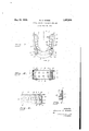
'is durable and tended, r. t M Other objects and advantages will appear in-the following specification, and the novel features ,of. the: device-will be particularly pointed out in the appended claims. a 10 My invention is illustrated in the accompanying drawings forming a part Of' lBl'llSi application, in which Figure 1 is a top plan view of the support; n Figure 2 is a front elevation; Figure 3 is a section along the line 33 of Figure 1; and
Figure 4 is a section alon Figure 1. V g In making a bridge it is first necessary to crown the teeth which are to be used for supporting the bridge. The bridge may be supported from abutments other than crowns, such as from inlays and Carmichael crowns: The patient then bites into a piece of plaster of Paris and'wh en this is removed the abutments are removed with it. Artificial teeth are now formed and are set in their proper places and are secured to each other by wax. I The plaster of Paris is now removed from the bridge and the dentist is ready to make g the line 4. 4 of of mayibe readily understood.
' 'now apbliedto theiinterior' of th B and C, and the bridge is forced 1e31, s r ia1n ;544, 554.1 J
use of myifnvention." The investment support to be presently described has investment; spread therein'andthenthe bridge is forced down into the'investment and as the invest-. ment sets'that portionof the investment ad-' 'jacent tothe wax is removed. Before proceeding further with the method I of forming the bridge I" will describe the par--" ticular type of investment sup'p c'ntiiand CD The. part B forms the front-ofkthe investment supportandit has-a top flange greater insizethan the bottom flange'2 '(see Figure 3) The flanges areseparated' from each other by a web 1 3 -whichyis perforated as at l (see F' g'ure'2). Thecentral'part,B, -j
This-support consists of three parts',iA B,
is curved and. is d'esignedtd receive-the'in vestment for supporting i the anterior teeth? 1 The side members- A and C are identical" andeach has a narrow'flange 5' at its top and awidefiange 16' at its base. separating the flanges is -"per'forated as" at 8 (see -Figure2). This wall abuts-the edge of Each part A iand' has legs 9 that' sa addlethe center part B andhav e'hooks -10;for* Y reinovably receiving I I fastening screws: 5 11; L
' The hooks are so fashioned that the sides "Af j and C can be swung angularly through small arcs for'zaccomm'odating-bridges of different 7 sizes. 'After the sides A'and Ghave been ad juste'd'thes'erews :ILmaybe tightened.-' From the foregoing'dscription oflthe'various parts ofithe-device,*the operation there- "I have already described how the b mentsrby means of waxls The. investment is the investment so that thecuspsjof the posterior teeth-face toward 'the wide flanges 6. The-anterior teeth have beenpositioned ;di-. 5
, rectly above the'inner edgefiof the'ifiange ,11
cing the bridge into the I at'the moment'oflfor investment and-thenvthe operator, while in theact: of inserting the'bridgein the invest ment; moves' -the' bridgefforwardly a slight w W ridgesr formed, iup-to thewpointwwheretheartificialf teeth are'heldlto eac-h other and'to the abut I eiparts-A, down into distance with respect to the support, so that the bridge will assume the position shown in Figure 3.
After the investment hardens portions of it are removed so as to expose the interior surface of the bridge and-to further expose all of the .wax. portions that connect the teeth together; Gare-mustbe taken in'ot to place any of the teeth in the bridge next to any vice 'wh'iclfi will (30.:
ports the arts of the metal holder; In order to get the correct adj ustment 'of 'thesupport prior to placing the bridge in position, the sides A and C are swung so thatthenarrow'flanges 5 just clear each side of the. brid e widest point of the bridge.
thefirstcto enter .theinvestment.-. After the surplus-investmentds cut awaysoaasetoexpose the wax on-theinside, this.
wax is boiled outtwith boiling-Water." The. support. or case, is..-now placed .over a; low flame and .the'investment; is gradually heated.
until it is thoroughly: dry.
The device isnowremoved to the solderitgis removeddromitheholder'or case.
fitted .into the patienfis mouth..-
The; investment-slopes-away from the inner surfacescof. the. teeth :so as -=to: expose all of..the-..portions.- to :bee soldered: The-inner: edges;.of:the flanges :1, .2, 5 and 6: terminate.
, flush; with-.-therinvestmentsozthat they-.will
not interfere: with the torch when used in solder into place. For this flowing the gold reason the flange 2 isof less width thanl the flange; 1 and the; flanges 5 of: lessaw-idth; than the flanges 6. IPha-Ve'indicated in Figure: 3,
by: the reference .nnmer al 125tl1e1'Wa'Xr1WhiCh holdsradjacent teethtogether; 1 This wax; of.
course, is. boiled out and gold. solder; takes :its
place -i and the purpose of the, investment is: 1 to hold. the; teeth 1 in aproper; position F while;
receivinggthergoldsolders.
The? flange'rfi ;is made wide-because itsup investment- .13, awhic'lrzin'zturn supports -the occlusal? surfaces ofzthe 1 posterior teethil laa.
teeth:
The support :orzcase provides a scompactrde= at the. The %ridge in being insertedrin the investmentzisheld so r thatihe biting surfaoesofthebridge will be mg 1 block; and. gold solder is applied with the-.aidiof a2 blew-v tor'ch so. that: this solder will flow into the spaces .forme'rlyoccupied bythenwaxQ Thegold solder: quickly sets-and.
. thebrid'ge: is now' allowed'to cool, after Will-lib bridge; is then trimmed and; polished and.
The {posterior I teetlihavea'theirrim i nerirsurfacesi'cutiaway? at". an angleand the"- flange: 5;: is maden-smallz enouglr. so. asnotito" interrereiwith the .gingival portionsiofi'these,
permit a. small; quantity of investment; to: bei-u'sed and 'which will ikeep thiscinvestmentaintact and. the case .-may' be:
. moved rea-dilyrinto any position": for; solder in'g Whensthe-three-parts'A, B, andzG of:
' the device are used an entire bridge; maybe:v 9. supported. IfsmalIer-bridges aretoxbe sup-'- ported one or more of the parts may be used. Although I have shown and described one embodiment of my invention it is to be understood that the same is susceptible of various changes and I reserve the right to employ such changes as may come within the scope of the claims hereto annexed.
I claim: r 1. A dental bridge investment support comprising a central curved perforated memb'er having-inwardly extending flanges at its in the central member for receiving: the;
hooks, .saidt, screws when .tightened' locking; the side-1 members. .to the; central one.
311A" dental. bridge. investment-:"support'. comprising aicentral curvedptort'ion and side hinged ifportions, all .of said portions 1 having inwardly extending flanges:
45A. dental bridge investment support 3 comprising a .central rcurved portiongand side hinged portions, all of saidportions having inwardly extending: flanges,-.said: flanges being :disposed at th e top and bottom" of the portions, the. top: flangeof ithe centerrporti on vand the bottom flanges: of the side .portions.m
being greater than the opposing flanges-car ried'by the same portions;
5. dental bridge investment support: comprising a, central P curved portion and side= hinged portions, all ofsaid; portions being perforated 1 and having inwardly extending flanges.
WILEIAM eo'ssn;
Priority Applications (1)
| Application Number | Priority Date | Filing Date | Title |
|---|---|---|---|
| US544554A US1857538A (en) | 1931-06-15 | 1931-06-15 | Dental bridge investment support |
Applications Claiming Priority (1)
| Application Number | Priority Date | Filing Date | Title |
|---|---|---|---|
| US544554A US1857538A (en) | 1931-06-15 | 1931-06-15 | Dental bridge investment support |
Publications (1)
| Publication Number | Publication Date |
|---|---|
| US1857538A true US1857538A (en) | 1932-05-10 |
Family
ID=24172649
Family Applications (1)
| Application Number | Title | Priority Date | Filing Date |
|---|---|---|---|
| US544554A Expired - Lifetime US1857538A (en) | 1931-06-15 | 1931-06-15 | Dental bridge investment support |
Country Status (1)
| Country | Link |
|---|---|
| US (1) | US1857538A (en) |
-
1931
- 1931-06-15 US US544554A patent/US1857538A/en not_active Expired - Lifetime
Similar Documents
| Publication | Publication Date | Title |
|---|---|---|
| Van der Velden | Regeneration of the interdental soft tissues following denudation procedures | |
| Gilboe et al. | Fundamentals of extracoronal tooth preparation. Part I. Retention and resistance form | |
| US2138254A (en) | Dental correlator | |
| LaTurno et al. | Straight-line endodontic access to anterior teeth | |
| Ellinger et al. | Single complete dentures | |
| Karkazis et al. | Relationship between ala-tragus line and natural ocelusal plane. Implications in denture prosthodontics. | |
| US1857538A (en) | Dental bridge investment support | |
| Browning et al. | Fabrication of a hollow obturator with fluid resin | |
| US3565387A (en) | Prefabricated dental pattern having adjusting slot means | |
| Wilcox et al. | Molar access: shape and outline according to orifice locations | |
| Moghadam | Preliminary impression in patients with microstomia | |
| US2600899A (en) | Dental appliance | |
| US4278426A (en) | Relator assembly | |
| Gazabatt et al. | A comparison of bone resorption following intraseptal alveolotomy and labial alveolectomy | |
| Smith et al. | Fabrication of removable stone dies using cemented dowel pins | |
| Chen et al. | An altered-cast impression technique that eliminates conventional cast dissecting and impression☐ ing | |
| SU1187813A1 (en) | Fixed dental bridge | |
| Blatterfein | Rebasing procedures for removable partial dentures | |
| US1502970A (en) | Artificial denture | |
| ES467915A1 (en) | Individual dental implant and a method for its application to a patient | |
| Teppo et al. | A method of immediate clasp repair | |
| Ruhlman et al. | A method for pontic stabilization in fixed partial denture construction | |
| US3354548A (en) | Apparatus for making dental crowns and bridges | |
| Kay | Fixed splints and fixed bridgework retained by horizontal pins | |
| Bruno | A one-piece fixed bridge |