US1857533A - Method of treating hydrocarbons - Google Patents
Method of treating hydrocarbons Download PDFInfo
- Publication number
- US1857533A US1857533A US172536A US17253627A US1857533A US 1857533 A US1857533 A US 1857533A US 172536 A US172536 A US 172536A US 17253627 A US17253627 A US 17253627A US 1857533 A US1857533 A US 1857533A
- Authority
- US
- United States
- Prior art keywords
- zone
- valve
- gas
- oil
- vapors
- Prior art date
- Legal status (The legal status is an assumption and is not a legal conclusion. Google has not performed a legal analysis and makes no representation as to the accuracy of the status listed.)
- Expired - Lifetime
Links
- 238000000034 method Methods 0.000 title description 23
- 229930195733 hydrocarbon Natural products 0.000 title description 18
- 150000002430 hydrocarbons Chemical class 0.000 title description 17
- 239000007789 gas Substances 0.000 description 32
- 239000003921 oil Substances 0.000 description 32
- 238000010438 heat treatment Methods 0.000 description 22
- 238000009835 boiling Methods 0.000 description 12
- 239000004215 Carbon black (E152) Substances 0.000 description 11
- 238000005336 cracking Methods 0.000 description 8
- 239000000126 substance Substances 0.000 description 7
- 238000010992 reflux Methods 0.000 description 6
- 239000007788 liquid Substances 0.000 description 5
- XLYOFNOQVPJJNP-UHFFFAOYSA-N water Substances O XLYOFNOQVPJJNP-UHFFFAOYSA-N 0.000 description 5
- 244000261422 Lysimachia clethroides Species 0.000 description 4
- 230000001105 regulatory effect Effects 0.000 description 4
- 238000001816 cooling Methods 0.000 description 3
- 230000000694 effects Effects 0.000 description 3
- 238000004519 manufacturing process Methods 0.000 description 3
- 239000000463 material Substances 0.000 description 3
- 238000009834 vaporization Methods 0.000 description 3
- 230000008016 vaporization Effects 0.000 description 3
- OKTJSMMVPCPJKN-UHFFFAOYSA-N Carbon Chemical compound [C] OKTJSMMVPCPJKN-UHFFFAOYSA-N 0.000 description 2
- 229910052799 carbon Inorganic materials 0.000 description 2
- 238000009833 condensation Methods 0.000 description 2
- 230000005494 condensation Effects 0.000 description 2
- 239000000470 constituent Substances 0.000 description 2
- 238000010276 construction Methods 0.000 description 2
- 230000008878 coupling Effects 0.000 description 2
- 238000010168 coupling process Methods 0.000 description 2
- 238000005859 coupling reaction Methods 0.000 description 2
- 230000005484 gravity Effects 0.000 description 2
- VNWKTOKETHGBQD-UHFFFAOYSA-N methane Chemical compound C VNWKTOKETHGBQD-UHFFFAOYSA-N 0.000 description 2
- 239000003345 natural gas Substances 0.000 description 2
- 238000003860 storage Methods 0.000 description 2
- 241000370685 Arge Species 0.000 description 1
- KUVIULQEHSCUHY-XYWKZLDCSA-N Beclometasone Chemical compound C1CC2=CC(=O)C=C[C@]2(C)[C@]2(Cl)[C@@H]1[C@@H]1C[C@H](C)[C@@](C(=O)COC(=O)CC)(OC(=O)CC)[C@@]1(C)C[C@@H]2O KUVIULQEHSCUHY-XYWKZLDCSA-N 0.000 description 1
- 238000004891 communication Methods 0.000 description 1
- 230000001276 controlling effect Effects 0.000 description 1
- 239000010730 cutting oil Substances 0.000 description 1
- XAEWZDYWZHIUCT-UHFFFAOYSA-N desipramine hydrochloride Chemical compound [H+].[Cl-].C1CC2=CC=CC=C2N(CCCNC)C2=CC=CC=C21 XAEWZDYWZHIUCT-UHFFFAOYSA-N 0.000 description 1
- 239000012467 final product Substances 0.000 description 1
- 239000000203 mixture Substances 0.000 description 1
- 101150008563 spir gene Proteins 0.000 description 1
Images

Classifications
-
- C—CHEMISTRY; METALLURGY
- C10—PETROLEUM, GAS OR COKE INDUSTRIES; TECHNICAL GASES CONTAINING CARBON MONOXIDE; FUELS; LUBRICANTS; PEAT
- C10G—CRACKING HYDROCARBON OILS; PRODUCTION OF LIQUID HYDROCARBON MIXTURES, e.g. BY DESTRUCTIVE HYDROGENATION, OLIGOMERISATION, POLYMERISATION; RECOVERY OF HYDROCARBON OILS FROM OIL-SHALE, OIL-SAND, OR GASES; REFINING MIXTURES MAINLY CONSISTING OF HYDROCARBONS; REFORMING OF NAPHTHA; MINERAL WAXES
- C10G9/00—Thermal non-catalytic cracking, in the absence of hydrogen, of hydrocarbon oils
- C10G9/34—Thermal non-catalytic cracking, in the absence of hydrogen, of hydrocarbon oils by direct contact with inert preheated fluids, e.g. with molten metals or salts
- C10G9/36—Thermal non-catalytic cracking, in the absence of hydrogen, of hydrocarbon oils by direct contact with inert preheated fluids, e.g. with molten metals or salts with heated gases or vapours
- C10G9/38—Thermal non-catalytic cracking, in the absence of hydrogen, of hydrocarbon oils by direct contact with inert preheated fluids, e.g. with molten metals or salts with heated gases or vapours produced by partial combustion of the material to be cracked or by combustion of another hydrocarbon
Definitions
- This invention relates to a method of cracking hydrocarbon oils, such-as the residue therefrom, and the particular application of the present invention is directed to the cracking of hydrocarbon oils, whereby the heavler ortions thereof will be converted into lower hoiling point portions or those :of higher Baum'gravity.
- the objects of the invention are "to provide a process in which the oil to be cracked is treated in first one receptacle or heating pool and then ina separate receptacle or zone and in which the oil in each receptacle or zone may be independently heated; to provide a process in which the oil in each zone may be subjected to the action of gases independently controllable relative to each zone; to provide a process in which both the volume and the pressure of the gases in each zone may be varied relative to, each other; to provide a process in which the oil in thesecend zone may take the form of vapors intro.- quizd from the first'zone; to prov'idea process in which the hydrocarbon constituents of the second zone may be heated to either a temperature higher or lower than the temperature of the oil in the first zone or heating pooland in general to provide an improved process of the characterreferredjto.
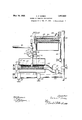
- v Fig. 1 is a diagrammatic side elevation of the apparatus partly in section.
- Fig. 2 is a sectional view of a portion of the apparatus taken on line 2-2 of Fig.1,"-
- Fig. 3 is a cross section through one of the 1 Fig. 4 is a cross section showing thecontrol of the perforated pipe.
- a gas pipe 7 connected at its lowerend with a horizontally extendin perforated pipe 8;
- the pipe 7 is provide with a suit able pressure gauge 9 and acutofi' valve 10, while.
- extending into the tube 1 from its upper end is a pyrometerll.
- This pi e 7 is connect ed to a su ply pipe 12 leading rom a suitable source 0 *supply of gas, such as natural gases, which it is desired to" inject into the contents of the still 1 through the perforated pipe-8:
- a suitable source 0 *supply of gas such as natural gases
- the pipesi12 and 7 may be connectf ed by a by-pass (not shown) around the pump 13in the usual manner; Inorder to rovide forlraisingthe temperature of the su stance injectedinto the still contents, a su'perheater lisremployed in the connection between the supply pipe 12 and the pipe-7,:althoughthe superheateri canxbe c'ut-outofthe circuit by closing the valves 15 andz16 and opening the valves-17 and 18. From the 'above descrip tion itwis obvious that the substance ejected froml-the pipe8 into the contents of the still may "be. forced out into the "pipe 8 at any desired pressure or temperature.
- a g0oseneckE19 w-hich connects with the condenser 20 in aplurality" of ways hereinafter described in detail.
- J '1 a i i Positioned in the upright of the gooseneck' 19 isja reflux-condenser 21,-this condenser comprising I a plurality of water bafiles 22 provided with a couplin around which circulate a water or other temperature controlling medium.
- laterals-23 and 24 Leading from the upright of the gooseneck 19 at a level below that in which the reflux condenser 21 is located, are laterals-23 and 24, entrance from the gooseneck 19 to these laterals being controlled by valves 25 and 26, and the entrance from the gooseneck 19 to the reflux condenser being controlled by similar valve 27.
- 23 is provided with a second cutoff valve 28 positioned just beyond the upright 29 which connects the laterals 23 with, an air condenser 30. Communication between this air condenser and the lateral 23 is controlled by cutoff valve 31.
- Each of the laterals 23 and 24 connect with the upright line 32, and the aircondenser 30 and reflux condenser 21 are also provided with connections to this line by vapor pipes 33 and 34, the latter having a valve 35 and the former a similar valve 36.
- Additional valves 37 and 38 are provided 'in' the lateral 24 and vapor line 32.
- the condenser 20 at its discharge end is 39 from the lower end of which is a disc arge openin controlled by weighted valve 40.
- ad usting the valve 40 any desired back pressure may be put on the still and condenser as is known in the art. This would permit subjecting the oil to a higher temperature as with pressure, the normal boiling points of the hydrocarbons will be raised.
- an escape .1 pipe 41 controlled by suitable valve 42.
- the coupling 39 has a lateral pipe 43 connected with a vacuum pump 44.
- a valve 45 is employedfor cutting oil the pump, and both the pump and M weighted valve control outlet lead to a suitable storage tank or other, receptacle (not shown).
- the temperature of the vapors at the time they pass into the lateral 24 is determined by a pyrometer which can be placed at the point marked 55, while the size of theopenings 56 in the perforated pipe 53 is controlled by means of a rotary sleeve valve 57 which is operated by an exterior injected substance is discharged into the substance treated
- a pyrometer which can be placed at the point marked 55
- a rotary sleeve valve 57 which is operated by an exterior injected substance is discharged into the substance treated
- Valves 25 and 26 may be closed, and valve 27 opened, valve 36 opened, valve 35 closed, valve 38 opened and the pressure controlled by the weighted valve 40 on the outlet side of the condenser. In this method of carrying out the process, the second zone formed by the' pipe 24 is not used.
- the vapor pressure on the system may be maintained at from 100 to 750 pounds, by suitably regulating the valve 40 and the gas outlet valve 42.
- An undondensable gas such as natural gas, may be introduce into the perforated pipe 8 throu h the line 7.
- a gas pressure of say, 1000 pounds, may be. maintained on the line 7 above the valve 10;
- the volume of gas introduced will be controlled by the valve 10.
- the pressure (which controls thevelocity) will be controlled by the valve 60. For example, itmay be desired to let in 500 cubic feet of gas per minute at a pressure of 200 pounds, which at the outset, can be accomplished by suitably by a valve 60 operated by a stem 61.
- the heavier vapors may be returned by the reflux condenser to the st ll for further treatment.
- valves 25 and 27 may be closed and I the valve 26 opened.
- the valve 37 may also be opened and the pressure controlled on the outlet side of the condenser as before.
- the oil in the still may be treated in identically the same way as before, but now the vapors will be independently heated in the zone or container 24 and if desired, may be superheated.
- the volume of gas introduced may be less than that in the main still 1, but the pressure on the gas entering the second zone may be maintained at say, in the first stage, 300 pounds, the second stage, 350 pounds and the third stage at 400 pounds, by suitably regulating the valve 58. It is to be understood, however, that the vapor pressure on the oil is controlled from the outlet side of the condenser and is in fact not controlled in any way by the pressure at which the gas is introduced.
- valves 25 and 26 are closed, and the valve 27 opened.
- the vapors then in passing to the condenser 20 are compelled to pass through the reflux condenser 21, the temperature at which this condenser is malntained being such as to condense and return to the still those vapors that do not have a low enough boiling point.
- the latter may be cut out by closing valve 27 andthe vapors compelled to pass through the lateral 24 where they may be subjected to the action of a substance injected through the perforated pipe 53.
- the temperature and pressure of the injected substance is sufliciently high to result in lowering the boiling point of the vapors treated.
- a further method of cracking oil in this apparatus may be described as follows:
- the whole system may be maintained under a predetermined pressure by regulating the outlet side of the condenser and either an uncondensable gas or other substance may or may not be introduced into the receptacle 1.
- the vapors, however, which pass into the receptacle 24 may be subjected to the action of uncondensable gas and introduced under a given pressure and volume to permit the gas to enter the chamber 24.
- a process for cracking heavy hydrocarbon oil for the production of gasoline-like hydrocarbons which comprises introducing the oil to an initial heating zone and heating the same therein to a temperature sufiicient to e'fieet sub'stantial vaporization T'ofthei oil,
- a process for cracking heavy hydro carbon oil for the production of gasolinelike hydrocarbons which comprises introduce ing the oil to an initial heating zone and heating the same therein to a temperature sufficient to effect substantial vaporization of the oil, passing the evolved vapors to a superheating zone to which no liquid oil from said initial heating zone is admitted, supere heating a gaseous material independently and exteriorly of said initial heating zone and said superheating zone, introducing the superheated gaseous material directly and without previous passage thru said initial heating zone to-said superheating zone and into physical contact with the va ors therein, the temperature and pressure 0 the superheated gaseous material injected into said superheating zone being sufiicientlyhigh to eflect a lowering of the boilin point of the j vapors therein, removing the converted vapors from said superheating zone and subjecting the same to condensation.
- a process for cracking heavy hydrocarfm bon oil' for the production of gasoline-like hydrocarbons which comprises introducing the oil to an initial heating zone and heating the same therein to a temperature suflicient to effect substantial vaporization of the oil passing the evolved vapors to a superheating a zone to which no liquid oil from said initial heating zone is.
Landscapes
- Chemical & Material Sciences (AREA)
- Oil, Petroleum & Natural Gas (AREA)
- Engineering & Computer Science (AREA)
- Physics & Mathematics (AREA)
- Thermal Sciences (AREA)
- Chemical Kinetics & Catalysis (AREA)
- General Chemical & Material Sciences (AREA)
- Organic Chemistry (AREA)
- Combustion & Propulsion (AREA)
- Production Of Liquid Hydrocarbon Mixture For Refining Petroleum (AREA)
Description
May 10, 1932. I c. P. DUBBS METHOD OF TREATING HYDROCARBONS Original Filed Feb. 17 1921 2 Sheets-Sheet May 10, 1932. c. P. DUBBS 1,857,533
METHOD OF TREATING HYDROCARBONS Original Filed Feb. 17. 1921 2 Sheets-Sheet 2 W fwmzazx WW Carbon PPM 7,5
. cannon P. nusssor wrmkn'rrn, 11114111015,ASSIGIFOEBL,Td:FNiFiElkSAI -QIL TBQDUCTS COMPANY, onenxcaeo, rumors,- AcoRronAmonor-somm naxo'ra j D bafiie plate tubes.
latented May 10, 1932 meag r 1m e me ses":
Continuation f a pmaudn' senai m5. 445,6 9, fi led February 17, 1 .21
i 192v. Serial No. 172,53
This application isv a continuation of my copending application Serial No. 445,662, filed February 17, 1921, which application s in part a continuation of an original application filed by me on November 18, 1914:, Serial No. 872,698.
This invention relates to a method of cracking hydrocarbon oils, such-as the residue therefrom, and the particular application of the present invention is directed to the cracking of hydrocarbon oils, whereby the heavler ortions thereof will be converted into lower hoiling point portions or those :of higher Baum'gravity. a
Among the objects of the invention are "to provide a process in which the oil to be cracked is treated in first one receptacle or heating pool and then ina separate receptacle or zone and in which the oil in each receptacle or zone may be independently heated; to provide a process in which the oil in each zone may be subjected to the action of gases independently controllable relative to each zone; to provide a process in whichboth the volume and the pressure of the gases in each zone may be varied relative to, each other; to provide a process in which the oil in thesecend zone may take the form of vapors intro.- duced from the first'zone; to prov'idea process in which the hydrocarbon constituents of the second zone may be heated to either a temperature higher or lower than the temperature of the oil in the first zone or heating pooland in general to provide an improved process of the characterreferredjto.
Inthe drawings: v Fig. 1 is a diagrammatic side elevation of the apparatus partly in section.
Fig. 2is a sectional view of a portion of the apparatus taken on line 2-2 of Fig.1,"-
but on an enlarged scale in order to more clearly bring out details of construction.
Fig. 3 is a cross section through one of the 1 Fig. 4 is a cross section showing thecontrol of the perforated pipe.
Referring in detall to the drawings, in order to more clearlyunderstand the use of the entire apparatus, it will be advisable to, describe the various; processes forwhich the an icawmuaaa apparatus can be utilized, although it is'to' be understood'that Iam here claiming only the conversionof high boiling point to lower boiling point oils. '1 designates the "still supported directly ovbr the furnace lugs 2, although various other' meansfor' heating the still might be employed. -At the'upper end the still is providedwith a-filling connection 3, and near the bottom with a drawoff cock 4. There'is'preferablyalso provided a pyrometerwallfi and'a weighted safety valve 6, all of these parts being of standard construction. Extending downward into the still is a gas pipe 7 connected at its lowerend with a horizontally extendin perforated pipe 8; The pipe 7 is provide with a suit able pressure gauge 9 and acutofi' valve 10, while. extending into the tube 1 from its upper end is a pyrometerll. This pi e 7 is connect ed to a su ply pipe 12 leading rom a suitable source 0 *supply of gas, such as natural gases, which it is desired to" inject into the contents of the still 1 through the perforated pipe-8: In certain instances, it may be desirable to increase the pressure under which the substance is forced out'of the perforated pipe 8 to a greater pressure than that under which the source of supply is maintained, and for thispu'rpose a pump :13 is employed, although if. desired, the pipesi12 and 7 may be connectf ed by a by-pass (not shown) around the pump 13in the usual manner; Inorder to rovide forlraisingthe temperature of the su stance injectedinto the still contents, a su'perheater lisremployed in the connection between the supply pipe 12 and the pipe-7,:althoughthe superheateri canxbe c'ut-outofthe circuit by closing the valves 15 andz16 and opening the valves-17 and 18. From the 'above descrip tion itwis obvious that the substance ejected froml-the pipe8 into the contents of the still may "be. forced out into the "pipe 8 at any desired pressure or temperature. p Leading from the top of the still is a g0oseneckE19 w-hich connects with the condenser 20 in aplurality" of ways hereinafter described in detail. J '1 a i i Positioned in the upright of the gooseneck' 19 isja reflux-condenser 21,-this condenser comprising I a plurality of water bafiles 22 provided with a couplin around which circulate a water or other temperature controlling medium. Leading from the upright of the gooseneck 19 at a level below that in which the reflux condenser 21 is located, are laterals-23 and 24, entrance from the gooseneck 19 to these laterals being controlled by valves 25 and 26, and the entrance from the gooseneck 19 to the reflux condenser being controlled by similar valve 27. 23 is provided with a second cutoff valve 28 positioned just beyond the upright 29 which connects the laterals 23 with, an air condenser 30. Communication between this air condenser and the lateral 23 is controlled by cutoff valve 31. Each of the laterals 23 and 24 connect with the upright line 32, and the aircondenser 30 and reflux condenser 21 are also provided with connections to this line by vapor pipes 33 and 34, the latter having a valve 35 and the former a similar valve 36.
The condenser 20 at its discharge end is 39 from the lower end of which is a disc arge openin controlled by weighted valve 40. By ad usting the valve 40 any desired back pressure may be put on the still and condenser as is known in the art. This would permit subjecting the oil to a higher temperature as with pressure, the normal boiling points of the hydrocarbons will be raised. Leading from the upper end of the coupling 39 is an escape .1 pipe 41 controlled by suitable valve 42. In
addition to these connections the coupling 39 has a lateral pipe 43 connected with a vacuum pump 44. A valve 45 is employedfor cutting oil the pump, and both the pump and M weighted valve control outlet lead to a suitable storage tank or other, receptacle (not shown).
In treating liquids which give a distillate having boiling points higher than water, the vapors are, by adjusting the valves 28 and 31,
' forced to pass through the air condenser 30 a ainst baflie plates 48 which condense such distillates as have boiling points, higher than water. Condensed distillates are collected into the bottom of the air condenser and overflow out of pipe 46 to suitable storage, the air condenser being maintained at a temperature above the boiling point of water by 0 ening or closing the valve. 7 on the bafile ate tubes 46, which are spir 1y corrugated.
he uncondensed oils and un ndensable gas pass through pipe 34 into vap line 32 and mtocondenser 20. Describing now the manner of heating the oil in the second zone, the supply pipe 12 and extension. 49' are connected to a second upright 50 by. an L,'the latter being provided with a control valve 51 and pressure gauge 52. At its lower\e1 1d the upright 50 discharges into a perforated pipe 53 similar to In addition to the valve 25 the lateral the perforated pipe 8 employed in the still. The perforated pipe 53 is located in the lateral 24 and the latter is surrounded by a furnace 54, (dia ammatically shown) the gas jets being omitted to avoid complicating the drawings, whereby its temperature may be raised if desired. The temperature of the vapors at the time they pass into the lateral 24 is determined by a pyrometer which can be placed at the point marked 55, while the size of theopenings 56 in the perforated pipe 53 is controlled by means of a rotary sleeve valve 57 which is operated by an exterior injected substance is discharged into the substance treated The following method of carryin .out the process in cracking oils may be use Valves 25 and 26 may be closed, and valve 27 opened, valve 36 opened, valve 35 closed, valve 38 opened and the pressure controlled by the weighted valve 40 on the outlet side of the condenser. In this method of carrying out the process, the second zone formed by the' pipe 24 is not used. The vapor pressure on the system may be maintained at from 100 to 750 pounds, by suitably regulating the valve 40 and the gas outlet valve 42. An undondensable gas, such as natural gas, may be introduce into the perforated pipe 8 throu h the line 7. A gas pressure of say, 1000 pounds, may be. maintained on the line 7 above the valve 10; The volume of gas introduced will be controlled by the valve 10. The pressure (which controls thevelocity) will be controlled by the valve 60. For example, itmay be desired to let in 500 cubic feet of gas per minute at a pressure of 200 pounds, which at the outset, can be accomplished by suitably by a valve 60 operated by a stem 61.
regulating the valves 10 and 60, since during the next stage of the operation as the lightest constituents have distilled oil", the same amount of gas may be introduced but the pressure raised to 250 pounds by further It will be clearly understood by those skil d "in the art that the vapor pressure, gas pressure and volume of gas and oil temperature will all vary widely with the characterof the oil being treated and the desired gravity of pressure distillate to be obtained.
The heavier vapors ma be returned by the reflux condenser to the st ll for further treatment.
- As an additional method of carrying out the process adapted for use in this apparatus, the valves 25 and 27 may be closed and I the valve 26 opened. The valve 37 may also be opened and the pressure controlled on the outlet side of the condenser as before. In this method, the oil in the still may be treated in identically the same way as before, but now the vapors will be independently heated in the zone or container 24 and if desired, may be superheated. In addition, the volume of gas introduced may be less than that in the main still 1, but the pressure on the gas entering the second zone may be maintained at say, in the first stage, 300 pounds, the second stage, 350 pounds and the third stage at 400 pounds, by suitably regulating the valve 58. It is to be understood, however, that the vapor pressure on the oil is controlled from the outlet side of the condenser and is in fact not controlled in any way by the pressure at which the gas is introduced.
In converting the higher boiling point oils to lower boiling point oils, such as in making gasoline from high boiling point residuums or distillates, the valves 25 and 26 are closed, and the valve 27 opened. The vapors then in passing to the condenser 20 are compelled to pass through the reflux condenser 21, the temperature at which this condenser is malntained being such as to condense and return to the still those vapors that do not have a low enough boiling point. In place of sending the vapors through the reflux condenser the latter may be cut out by closing valve 27 andthe vapors compelled to pass through the lateral 24 where they may be subjected to the action of a substance injected through the perforated pipe 53. The temperature and pressure of the injected substance is sufliciently high to result in lowering the boiling point of the vapors treated.
A further method of cracking oil in this apparatus may be described as follows: The whole system may be maintained under a predetermined pressure by regulating the outlet side of the condenser and either an uncondensable gas or other substance may or may not be introduced into the receptacle 1. The vapors, however, which pass into the receptacle 24 may be subjected to the action of uncondensable gas and introduced under a given pressure and volume to permit the gas to enter the chamber 24.
I claim as my invention:
1. A process for cracking heavy hydrocarbon oil for the production of gasoline-like hydrocarbons which comprises introducing the oil to an initial heating zone and heating the same therein to a temperature sufiicient to e'fieet sub'stantial vaporization T'ofthei oil,
passing the evolved vaporjsl to a superi heat ing zone to which gnol-iquidoil from'qfsa'idg initial heating-zone is admitted, superheating 'p'erma'Iren'thydrocarbon; gas: independently i exteriorlyf of isai'd initial heating, zone 1 maintained-in said initial heating l'zones and:
in'i'th'e; ia'bsence iof liquidiaoil from said: initiali heating" 1zone, removing the J: superheated? v apors iand "said! gas :r m said-"superheating z'on'e and-cooling the same sufiici ently to .con-i ing't-he resultant" fzthe processi 1" 212A- hydrocarbon. which comprises introducing xtlieioil't to .a' 'dis-r.v
tilling zone and: heating the same therein to acracking temperature 'iunder superatmosi- 1 phoric": pressure, passing; the 1 evolved :vapors free-of liquid oilfromisaid distilling zone'rto" atsuperheating zone-, superheating. a iperma nent hydrocarbon gas independently and ex- ,1
tcriorly of said distilling. and superheating zones, passing one portion of the superheated gas thru the liquid oil in said distilling zone, passing another portion of the superheated gas directly and without previous passage thru said distilling zone to said superheating zone and into physical contact with the vapors therein, superheating the vapors in said superheating zone to a temperature in excess of the cracking temperature maintained' in said distilling zone, removing the superheated vapors 'and said gas from said superheating zone and cooling the same sufficiently to condense said vapors out of the gas, and-collecting the resultant distillate as the final product of the process.
3. A process for cracking heavy hydro carbon oil for the production of gasolinelike hydrocarbons which comprises introduce ing the oil to an initial heating zone and heating the same therein to a temperature sufficient to effect substantial vaporization of the oil, passing the evolved vapors to a superheating zone to which no liquid oil from said initial heating zone is admitted, supere heating a gaseous material independently and exteriorly of said initial heating zone and said superheating zone, introducing the superheated gaseous material directly and without previous passage thru said initial heating zone to-said superheating zone and into physical contact with the va ors therein, the temperature and pressure 0 the superheated gaseous material injected into said superheating zone being sufiicientlyhigh to eflect a lowering of the boilin point of the j vapors therein, removing the converted vapors from said superheating zone and subjecting the same to condensation.
4. A process for cracking heavy hydrocarfm bon oil' for the production of gasoline-like hydrocarbons which comprises introducing the oil to an initial heating zone and heating the same therein to a temperature suflicient to effect substantial vaporization of the oil passing the evolved vapors to a superheating a zone to which no liquid oil from said initial heating zone is. admitted, superheating incondensible hydrocarbon gas independently and exterior-1y of said initial heating zone and said superheating zone, introducing thesuperheated incondensible hydrocarbon gas directly and without previous passage thru said initial heating zone to said superheating zone and into physical contact with the vago pors therein, the temperature and pressure of the superheated incondensible hydrocarbon gas injected into said superheating zone being sufficiently high to effect a lowering of the boiling point of the vapors therein, re 5 moving the converted vapors to said incondensible hydrocarbon gas from said superheating zone and cooling the mixture suflicient ly to separate the vapors from the gas by condensation. 3o CARBON P. DUBBS.
Priority Applications (1)
| Application Number | Priority Date | Filing Date | Title |
|---|---|---|---|
| US172536A US1857533A (en) | 1927-03-03 | 1927-03-03 | Method of treating hydrocarbons |
Applications Claiming Priority (1)
| Application Number | Priority Date | Filing Date | Title |
|---|---|---|---|
| US172536A US1857533A (en) | 1927-03-03 | 1927-03-03 | Method of treating hydrocarbons |
Publications (1)
| Publication Number | Publication Date |
|---|---|
| US1857533A true US1857533A (en) | 1932-05-10 |
Family
ID=22628124
Family Applications (1)
| Application Number | Title | Priority Date | Filing Date |
|---|---|---|---|
| US172536A Expired - Lifetime US1857533A (en) | 1927-03-03 | 1927-03-03 | Method of treating hydrocarbons |
Country Status (1)
| Country | Link |
|---|---|
| US (1) | US1857533A (en) |
Cited By (1)
| Publication number | Priority date | Publication date | Assignee | Title |
|---|---|---|---|---|
| WO2021055448A1 (en) * | 2019-09-16 | 2021-03-25 | Figene, Llc | Treatment of disc degenerative disease and stimulation of proteoglycan synthesis by fibroblast conditioned media and formulations thereof |
-
1927
- 1927-03-03 US US172536A patent/US1857533A/en not_active Expired - Lifetime
Cited By (1)
| Publication number | Priority date | Publication date | Assignee | Title |
|---|---|---|---|---|
| WO2021055448A1 (en) * | 2019-09-16 | 2021-03-25 | Figene, Llc | Treatment of disc degenerative disease and stimulation of proteoglycan synthesis by fibroblast conditioned media and formulations thereof |
Similar Documents
| Publication | Publication Date | Title |
|---|---|---|
| US1857533A (en) | Method of treating hydrocarbons | |
| US1842105A (en) | Method of making asphalt | |
| US1678126A (en) | Process and apparatus for cracking mineral oil | |
| US1241979A (en) | Process of and apparatus for producing light hydrocarbons. | |
| US1484445A (en) | Method of treating hydrocarbons | |
| US1892452A (en) | Process for cracking hydrocarbon oil | |
| US1969782A (en) | Distilling and conversion process | |
| US1847082A (en) | Method of treating hydrocarbons | |
| US1675462A (en) | Process of producing high-viscous lubricating oil and high-grade asphalt from petroleum | |
| US1392584A (en) | Art of distilling petroleum-oils | |
| US1931757A (en) | Process for cracking hydrocarbon oils | |
| US1624889A (en) | Method of treating hydrocarbons | |
| US1546634A (en) | Apparatus for treating petroleum | |
| US1865189A (en) | Process and apparatus for treating hydrocarbons | |
| US1861956A (en) | Process for decomposing organic materials | |
| US1569855A (en) | Process of treating oil | |
| US1843742A (en) | Apparatus for treating hydrocarbons | |
| US1893907A (en) | Fractionating method | |
| US1811309A (en) | Process and apparatus for producing low boiling point hydrocarbon oils | |
| US1220504A (en) | Apparatus for dehydrating hydrocarbon-oils. | |
| US2048546A (en) | Petroleum refining system | |
| US2067832A (en) | Apparatus for converting higher boiling hydrocarbons into lower hydrocarbons | |
| US1923016A (en) | Process and apparatus for treating hydrocarbons | |
| US2051462A (en) | Method of treating petroleum residues | |
| US1993503A (en) | Cracking normally incondensable hydrocarbon gases |