US1857531A - Furnace regulator - Google Patents
Furnace regulator Download PDFInfo
- Publication number
- US1857531A US1857531A US348650A US34865029A US1857531A US 1857531 A US1857531 A US 1857531A US 348650 A US348650 A US 348650A US 34865029 A US34865029 A US 34865029A US 1857531 A US1857531 A US 1857531A
- Authority
- US
- United States
- Prior art keywords
- contact
- motor
- contacts
- circuit
- biased
- Prior art date
- Legal status (The legal status is an assumption and is not a legal conclusion. Google has not performed a legal analysis and makes no representation as to the accuracy of the status listed.)
- Expired - Lifetime
Links
- 230000001105 regulatory effect Effects 0.000 description 15
- 230000001276 controlling effect Effects 0.000 description 10
- 230000007246 mechanism Effects 0.000 description 10
- 238000004804 winding Methods 0.000 description 9
- 230000004044 response Effects 0.000 description 7
- 239000002184 metal Substances 0.000 description 6
- 230000001681 protective effect Effects 0.000 description 5
- 238000010276 construction Methods 0.000 description 4
- 239000000446 fuel Substances 0.000 description 4
- 230000008859 change Effects 0.000 description 2
- 230000009467 reduction Effects 0.000 description 2
- 241000501754 Astronotus ocellatus Species 0.000 description 1
- 230000002159 abnormal effect Effects 0.000 description 1
- 230000009471 action Effects 0.000 description 1
- 238000007792 addition Methods 0.000 description 1
- 230000000694 effects Effects 0.000 description 1
- 230000002452 interceptive effect Effects 0.000 description 1
- 238000000034 method Methods 0.000 description 1
- 230000004048 modification Effects 0.000 description 1
- 238000012986 modification Methods 0.000 description 1
- 230000008569 process Effects 0.000 description 1
Images
Classifications
-
- F—MECHANICAL ENGINEERING; LIGHTING; HEATING; WEAPONS; BLASTING
- F23—COMBUSTION APPARATUS; COMBUSTION PROCESSES
- F23N—REGULATING OR CONTROLLING COMBUSTION
- F23N1/00—Regulating fuel supply
Definitions
- thermo-responsive means In automatic furnace regulators the motive power mechanism is usually controlled by control contacts actuated by thermo-responsive means, andsince such thermo-responi0 sive means operates rather slowly the motive power mechanism is preferably controlled by such thermo-re-sponsive means through the medium of an intermediary such as a relay.
- Dampers and fuel flow control devices are preferably operated through the medium-of reciprocated means operated from a rotary crank so that one-half of the rotation of such crank closes the dampers or fuel flow. devices and the other half rotation of such crank opens the dampers or fuel flow devices.
- the relay means maybe operated or loaded to its contact open position by the motor without .actually breaking the motor circuit until after the reloading function has been entirely completed, whereby it is assured that if the spring actuated contact is released by such electro-responsive means such spring actuated contact may again assume its circuit closing position.
- Fig. 1 illustrative conventionally one emtwo positions.
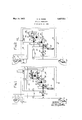
- Fig. 2 shows the preferred form of the invention in which a single trip coil is used for controlling the mechanism to either of its Referringto Fig. 1 of the drawings, "a double throw thermal controlled contact mechanism, conveniently called a thermostat, is shown within the dotted rectangle 3, and comprises a spiral 4 of bi-m-etallicthen mo-metal, a movable contactt and two stationary contacts 6. and 7.
- the bi-metallic metal is of such construction that an increase in temperature moves the contact inthe direction ofthe arrow 8.
- the reference character 10 denotes suitableheating means, such as a furnace, having a suitableheat control device 11 such as a gas or oilvalve or a' damper, which is. controlled by said thermostat through the; medium of the-regulating machine RM confined within the dotted rectangle 12.;
- the thermostat is located in the apartment where the temperature is to be kept constant, whereas therregulating machine is preferably located near the furnace asin the basement of the dwelling.
- the regulating machine includes, amain crank shaft 15 which is operated by a suitable PATENT, QFFZI'CE;
- This shaft 15 contains a crank 18, which through a chain or cable'19, passing over pulleys 20,. opens and *closes the damper 11.
- On this shaft 15 arecontained two insulated cams or contactors 22 and 23, of which the cam 22 is used to re'storethe spring actuated contacts24 and 25to their normal latched position, and the cam 23 is usedto connect the wire 26 to either of the wires 27 and 28.
- contacts 2 1 and 25 are spring leaf contacts held by fixed supports 29. and 30, and are biased toward each other. into contacting en- 'di cated by arrows, of which the contact 24 is gagement with their stationary contacts in- I held open by the cam 22 and the contact 25 is held open by the latch 35.
- Thelatch 34' is also in position to preventiclosureof contact .100"
- Thisv mechanism RM including the transformer T, is preferably mounted in a casing with the crank 18 projecting thereupon.
- relay means which is restored :by the motor in a manner to store energy therein for again reclosing the motor circuit
- latch means for holding one of said biased contacts in a position not to contact with the other biased contact, and an electro-magnet connected to one of said stationary contacts for. releasing said latch.
- a regulating machine for operating furnace dampers comprising, a motor for. operating a damper, contacts biased toward each other for controlling the flow of current to said motor, a latch for holding one of said contacts away from the other contact, means operated by said motor for moving said contacts when in contacting relationship to a position where said one contact may be en'- gaged by said latch and then releasing said contacts thus opening said motor circuit, and c an electro-magnet for releasing said latch.
- a temperature regulating device the combination with a shaft, heat. control means operated by said shaft, a motor for driving said shaft, a relay for controlling said motor which if operated to its activecondition applies current to sai'd'motor, said, relay including two spring fingers biased toward each other and holding means for holding one finger, away from the other finger, and means operated by said motor for moving both of said fingers in a position so that said one finger may beheld by said holding means and then disengaging said other finger and allowing it to beoperated quickly to its biased normal position where it is out of engagement with said one finger.
- an electric motor for operating suitable heat control means a relay having a normallyopen contact biased to the closed position and normally maintained open which if closed will remain closed until said motor has operated through apredetermined cycle, electrically operated means for allowing closure of said contact, and a circuit for said motor including said normally open contact.
- an electric motor for operating suitable heat control means a circuit'for controlling said motor, a normally open contact in said circuit biased to tend to assume the closedposition, control means responsive to a momentary flow of c'urrent'to allow closure of'said contact, said control means maintaining said contact closed if once closed until said motor hasoperated-through a predetermined cycle,
- a heat regulating system the combination with a furnace regulating machine having a plurality of control circuits and which will operate until it assumes a position where the energized control circuit is broken by a switch within the regulating machine, said switch comprising contact members biased toward each other and biased toward a normal position, an abutment for holding one of said contact members out of contact with the other, and an electro-magnet in the energized control circuit for withdrawing said abutment and thereby engaging said contact members, and a thermostat for energizing anyone of said control circuits but only one at a time.
- the-combination with a furnace regulating machine having a plurality of control circuits and which will operate until it assumes a position where the energized control circuit is broken by a switch within the regulating machine, said switch comprising contact members biased toward each other and biased toward a normal position, an abutment for holding one of said contactmembers out of' contact with the other, and an electro-magnet in the energized control circuit for withdrawing said abutment and thereby engaging said contact members.
- a heat regulating system the combination with a furnace regulating machine having a plurality of control circuits and which will operate until it assumes a posi-' tion where the energized control circuit is broken by a switch within the regulating machine, said switch comprising contact members biased toward each other and biased toward a normal position, anabutment for holding one of said contact membersout of contact'with the other, and electro-magnet in the energized control circuit for withdrawing said abutment and thereby engaging said contact members, and means for opening said circuit by snap action comprising a member actuated by said machine for moving said contact members to a position Where one of them is located behind said abutment so that upon 7 withdrawal of said restoring member the abutment will support oneof said contact members allowingthe other contact member to move away and opening the circuit.
Landscapes
- Engineering & Computer Science (AREA)
- Chemical & Material Sciences (AREA)
- Combustion & Propulsion (AREA)
- Mechanical Engineering (AREA)
- General Engineering & Computer Science (AREA)
- Motor And Converter Starters (AREA)
Description
0 H. DICKE FURNACE REGULATOR May 10, 1932.
Filed March 20, 1929 F I I I I I I I l Patented May 10, 1932 UNITED STATES] OSCAR n. DICKE, or ROCHESTER, NEW YORK, 'Assienon T rronEEa HEAT. REGULATOR CORPORATION, A CORPORATION on NEW JERSEY FURNACE REGULATOR Application filed March 20, 1929. Serial 110,348,650.
dampers and fuel flow control devices.
In automatic furnace regulators the motive power mechanism is usually controlled by control contacts actuated by thermo-responsive means, andsince such thermo-responi0 sive means operates rather slowly the motive power mechanism is preferably controlled by such thermo-re-sponsive means through the medium of an intermediary such as a relay.
Dampers and fuel flow control devices are preferably operated through the medium-of reciprocated means operated from a rotary crank so that one-half of the rotation of such crank closes the dampers or fuel flow. devices and the other half rotation of such crank opens the dampers or fuel flow devices.
' TWith theabove and other important .con-
siderations in mind, it is proposed in accord ance with the present invention-toemploy crank operated reciprocating means driven by an electric motor through the mediumof reduction gearing, to control such motor by relay means constituting a spring actuated normally open contact reloadablethrough the medium of. said motor and releasable by electro-responsive means controlled by a thermo-responsive contact.
In'accordance with the preferred form of the invention it is proposed to so construct the above mentioned mechanism, that the relay means maybe operated or loaded to its contact open position by the motor without .actually breaking the motor circuit until after the reloading function has been entirely completed, whereby it is assured that if the spring actuated contact is released by such electro-responsive means such spring actuated contact may again assume its circuit closing position.
Other objects, purposes and characteristic features will be understood from the drawings and accompanying description.
2 In describing the invention in detail referencev will be had to the accompanying draw-.
ings in which:
Fig. 1 illustrative conventionally one emtwo positions.
bodiment of the invention in which two strip coils are used for controlling the mechanism to itstwo positions; and, V
Fig. 2 shows the preferred form of the invention in which a single trip coil is used for controlling the mechanism to either of its Referringto Fig. 1 of the drawings, "a double throw thermal controlled contact mechanism, conveniently called a thermostat, is shown within the dotted rectangle 3, and comprises a spiral 4 of bi-m-etallicthen mo-metal, a movable contactt and two stationary contacts 6. and 7. The bi-metallic metal is of such construction that an increase in temperature moves the contact inthe direction ofthe arrow 8.
The reference character 10 denotes suitableheating means, such as a furnace, having a suitableheat control device 11 such as a gas or oilvalve or a' damper, which is. controlled by said thermostat through the; medium of the-regulating machine RM confined within the dotted rectangle 12.; In practicing the invention the thermostat is located in the apartment where the temperature is to be kept constant, whereas therregulating machine is preferably located near the furnace asin the basement of the dwelling. U i
. The regulating machine includes, amain crank shaft 15 which is operated by a suitable PATENT, QFFZI'CE;
motor M, through'reduction.gearing conventionally shown by worm 1 6 and worm'wheel 17. This shaft 15 contains a crank 18, which through a chain or cable'19, passing over pulleys 20,. opens and *closes the damper 11. On this shaft 15 arecontained two insulated cams or contactors 22 and 23, of which the cam 22 is used to re'storethe spring actuated contacts24 and 25to their normal latched position, and the cam 23 is usedto connect the wire 26 to either of the wires 27 and 28. The
contacts 2 1 and 25 are spring leaf contacts held by fixed supports 29. and 30, and are biased toward each other. into contacting en- 'di cated by arrows, of which the contact 24 is gagement with their stationary contacts in- I held open by the cam 22 and the contact 25 is held open by the latch 35. Thelatch 34'is also in position to preventiclosureof contact .100"
25 when the cam 22 is moved out of engagement with spring 24. The latch 34 is biased against the stop 40 by a spring 38 and the latch 35 is biased against the stop 41 by a spring 39. These spring contacts 24 and 25 may at proper times be caused to be operated to their abnormal position by electromagnets 36 and 37, respectively. Thisv mechanism RM, including the transformer T, is preferably mounted in a casing with the crank 18 projecting thereupon.
0pemtz'0n.Referring to Fig. 1, let us assume that the temperature of the apartment drops and the contact 5 in response thereto moves toward the left against its stationary contact 6, this does not produce any effect because the circuit in which contact 6 is contained is open at the contacts 23 and 54, this because the furnace damper 11 is already open.
Let us now assume with the damper 11 still open the room temperature rises and the con tact 5 is operated toward the right and in the direction of the arrow 8 in response to this temperature change, this completes a circuit through the electro-magnet 37 as follows beginning at the secondary winding of transformer T, wire 45, thermostat metal 4, contacts 5-7, wire 46, winding of the electromagnet 37, wire 27, contacts 14 and 23, wire 26, back to the transformer T. The completion of this circuit attracts the latch armature 35, pivoted at its lower end, thereby releasing the spring contact 25 biased to close and closing the following circuit through the motor M:beginning at the 110V source, wires 47 and 48, spring contact 25, wires 49 and 50,'field winding 51 and armature 52 of the motor M, wire 53, backto the 110V source. The completion of this circuit operates the motor to turn the main crank shaft 15 ina clock-wise direction, thereby breaking the circuit through the electro-magnet 37 at the contacts 14 and 23 and operating the damper 11 to its closed position. The motor is maintained in operation only through 180 movement of the crank 18, because after such movement the cam 22 restores the spring contact 25 to its latched position and again breaks the motor circuit at the contact 25. When this 180 movement of the shaft 15 is completed the contact 23 is in engagement with the stationary contact 54 thereby establishing a circuit for the electromagnet 36, which may be completed upon movement of the thermostat contact 5 toward the left. It should be noted that with the main crank shaft 15 moved through an angle of 180 the cam 22 will assume its lower position and therebyfree the spring contact. 24
so that upon release of this contact by the If now the temperature of the. apartment drops slightly, the contact 5 will be moved the clockwise direction.
to the left (the regulating machine now assuming the closed damper position) thereby completing the following circuit for the electro-magnet 36 :beginning at the'secondary winding of transformer T, wire 45, thermostat metal 4, contacts 56, wire 55, winding of the electro-magnet 36, wire 28, contacts 5423, wire 26, back to the transformer T. The completion of this circuit causes the latch armature 34 to be attracted, thereby employed in Fig. 1 it is believed unnecessary to describe the structure separately, and it is believed that the invention may be best understood by considering the operation thereof and in pointing out structural differ ences therein,certain partsbeing given like reference characters as corresponding parts in Fig. 1 with distinctive exponents.
Operation Fig 2.Let us first assume that the temperature of'the' apartment drop-s and that in response tothis temperature change the thermostat contact 5 is moved" toward the left. This movement of contact 5 does not complete a circuit because i the circuit is open'at the contact 23 '54 this being the case because the furnace is already open. Let us now assume that the temperature of the apartment rises, and thatvthe thermostat contact 5 is moved toward the right, under which condition the following circuit is completed :-'-beginning at the transformer T wire 60, thermostat metal 4 contact 5 7 wire 61, contacts 14 23 Wire 62, winding of the electro-magnet 63, wire 64, protective contact 65, wire 66 back to the transformer T. The completion of this circuit causes the latch 67 to be attracted against the tension of the spring 68 and away from the stop 69, thereby releasing the spring memher 7 0 and permittingthe projecting contact stud 71 to engage the stationary spring contact 72. With the contacts 71-72 closed the following circuit for the motor M is completed :beginning at the 110V source, wires 73, spring member .70, contacts 7172 wire 74, armature 52 and field winding 51 of the motor M, wire 75 back to the 110V source. The completion of this circuit causes the motor to operate the crank shaft 15 in As the main shaft 15 nears the end of a 180 movement the lug 77 engages the contact 72, which already in engagement with contact 71, thereby causing the lug 77 to raise the contacts 72 and 71 and with them raise the spring member 7 0 to and above the normal latched position, from which it is noted that the normal circuit is not opened due to the restoration of the spring member 70. As soon :as the lug 7 7 however, gets beyond the end of the spring contact72the spring 72 by its'bias'returns to its normal position, thereby breaking the circuit for themotor M 7 From this it appears that the motor has broken its owncircuit after the necessary energy for breaking that circuit has. been supplied, and that the restoring lug 77 has assumed a non-interfering position, as is not the case in Fig. 1. Inother words, al-' though the motor is used for restoring contact 71 and 72 to their normal open, or loaded, position to break its own circuit, this is accomplished in away so that upon'rele'ase of the contact spring 72 by the cam 77,'the contacts 7172 are opened, and this does not occur until the parts are in such position that release of the latch 67 of the relay mechanism permits contacts 71'72 to again close. Also, the actual breaking energy of the motor circuit does not occur until the energy for elfecting such breaking has been stored in the spring contact 72 and this process of storing energy requires the restoration of spring member so that it is assured that the entire restoration operation is completed beforethe motor current is actually out ofi.
It is therefore notedthat not only does the perature otthe apartment drops and the'contact 5 is moved toward the leftin engagementwith the stationary contact 6 a This completes the following circuit -beginning at the transformer T wire 60, thermostat metal 4 contacts 5 6 'wire 80, contact 54E 23 wire 62, winding of the electromagnet 63, wire 64, protective contact'65, wire 66 back to the secondary winding transformer T Completion of this circuit again trips the latch armature 67, thereby opening protective contact 65 and closing contacts 71-72 and causing operation of the motorM to return the apparatus back to the normal furnace-open position; It should be noted that each time spring" contact mechanism 7 O7172 is tripped that the protective contact 65 is immediately broken. This is done so as to assure that no arcing shall occur at the thermostat contacts 5 6 -7 it being understood that the instant the tripping circuitis completed through the thermostat con: tacts *the latch 67 is attracted and the protective contact 65' is opened. Also, itshould be noted that the contacts 71--72 are not only quick-make but also will quick-breakso as to limitarcing to a minimum.
In addition-to the various advantages of the present invention alreadypointed out,
it may be stated that it is highly desirable to employ relay means which is restored :by the motor in a manner to store energy therein for again reclosing the motor circuit, and
is tripped bya comparatively small electromagnet, the prmcipalwork being done by:
electro-magnet; Another feature ofthe in vention resides in the construction whereby the'same contacts and relay mechanismmay be used for operating theregulating machine from either extreme position to the othenexg treme position, this construction being such that the mechanical restoring mechanism operated'by-the motor isonewhich may be said to be self-clearing in that the motor breaks its own circuit onlyafter'the apparatus has I already been relatched; p a,
Having thus shown and des'cribedtwo em bodiments of the presentinvention and hav ing shown several rather specific circuit-tarit is desired to be understoodthat the devices and circuits selectedhave been selected for the purpose of facilitating illustration and description of the invention and have not been resorted to with the intent of disclosing the scope of the invention or the exact construction preferably employed in practicing thesame, and that various changes,
modifications, and additions may be made for 'carrylng out the invention without departing from the spirit or scope thereof or the idea of means underlyingthe same, except as demanded by the scope of the following claims.
What Iclaim is 1." In a temperatureregulating. device, the
combination with aishjaftyofa crank on said shaft, heat control "means operated by said crank, amotor for driving saidshaft, a re-' lay for controlling said motorwhich if operated to its active condition applies current to said motor, said relay includingtwo spring fingersbiased toward each other and holding means for holding'one finger away from the other finger, and means operated by said motor for movingboth of said fingers in a pcthe motor itself-and the control being car- 3 ried out through the medium of such small rangements for carrying out the invention,
sition so thatsaid one fingerjmay befheldby said holding means and then disengaging said other finger and allowing it to be operated quickly to its biased normal position where it is out of engagement with said one 2; In a'system of temperature controlin which the heat' fiow control devicesiar'e operated in response to the application ofpotential to one or the other of two stationary contacts by a movable thermal controlled contact, of a crank for controlling a heat flow control device, a motor driving said crank,
biased contacts in said motor circuit biased.
to the closed position, latch means for holding one of said biased contacts in a position not to contact with the other biased contact, and an electro-magnet connected to one of said stationary contacts for. releasing said latch.
3. In a system of temperature control in which the heat flow control devices are operated in response to the application of potential to one or the other of two stationary contacts by a movable thermal controlled contact, of a crank for controlling a heat flow control device, a motor driving said crank, biased contacts in said motor circuit biased to the closed position, latch means for holds ing one of said biased contacts ina position not to contact with the other biased contact, means operated by said motor for moving both of said biased contacts while in contaciting relationship to a position where said one contact may be engaged by said latch and then quickly releasing both of said contacts whereby said one contact is held in its latched position and the-other contact is freed to open-said motor circuit, and an electro-magnet for releasing said latch at times connected to one and at times connected to the other of said stationary contacts.
, 4. A regulating machine for operating furnace dampers comprising, a motor for. operating a damper, contacts biased toward each other for controlling the flow of current to said motor, a latch for holding one of said contacts away from the other contact, means operated by said motor for moving said contacts when in contacting relationship to a position where said one contact may be en'- gaged by said latch and then releasing said contacts thus opening said motor circuit, and c an electro-magnet for releasing said latch.
5. In a temperature regulating device, the combination with a shaft, heat. control means operated by said shaft, a motor for driving said shaft, a relay for controlling said motor which if operated to its activecondition applies current to sai'd'motor, said, relay including two spring fingers biased toward each other and holding means for holding one finger, away from the other finger, and means operated by said motor for moving both of said fingers in a position so that said one finger may beheld by said holding means and then disengaging said other finger and allowing it to beoperated quickly to its biased normal position where it is out of engagement with said one finger.
6. In a system of temperature control in which'the heat flow control devices are operated in response to the application of pocontacts for releasingsaid latch.
tential to one or the other of two stationary contacts by a movable thermal controlled contact, the combination with a shaft for controlling the heat flow control device, of a 'with the other biased contact, and an electromagnet connected to one of said stationary 7.; In a system of temperature control in which the heat flow control devices are operated/in response to the application of potential to one or the other of twostationary contacts by a movable thermal controlled contact, the combination with a shaft for controllingthe heat flow control device of a motor driving said shaft, biased contacts in said motor circuit biased to the closed position, latch means for holding one of said biased contacts in a position not to contact with the other biased contact, means operated by said motor for moving both of said biased contacts while in contacting relationship to a position where-said one contact may be engaged by said latch and then quickly releasing both of said contacts whereby saidone contact is heldin its latched position and the other contact is freed to open said motor circuit, and an electro-magnet for releasing said latch at times connected to one and atv times connected to the other of said station'- ary contacts.
8-. In a temperature regulating system, an electric motor for operating suitable heat control means, a relay having a normallyopen contact biased to the closed position and normally maintained open which if closed will remain closed until said motor has operated through apredetermined cycle, electrically operated means for allowing closure of said contact, and a circuit for said motor including said normally open contact.
9; In a temperature regulating system, an electric motor for operating suitable heat control means, a circuit'for controlling said motor, a normally open contact in said circuit biased to tend to assume the closedposition, control means responsive to a momentary flow of c'urrent'to allow closure of'said contact, said control means maintaining said contact closed if once closed until said motor hasoperated-through a predetermined cycle,
and thermal responsive means for controlling said control means.
10. In a heat regulating system, the combination with a furnace regulating machine having a plurality of control circuits and which will operate until it assumes a position where the energized control circuit is broken by a switch within the regulating machine, said switch comprising contact members biased toward each other and biased toward a normal position, an abutment for holding one of said contact members out of contact with the other, and an electro-magnet in the energized control circuit for withdrawing said abutment and thereby engaging said contact members, and a thermostat for energizing anyone of said control circuits but only one at a time. a V
11. In a heat regulating system, the-combination with a furnace regulating machine having a plurality of control circuits and which will operate until it assumes a position where the energized control circuit is broken by a switch within the regulating machine, said switch comprising contact members biased toward each other and biased toward a normal position, an abutment for holding one of said contactmembers out of' contact with the other, and an electro-magnet in the energized control circuit for withdrawing said abutment and thereby engaging said contact members.
12. In a heat regulating system, the combination with a furnace regulating machine having a plurality of control circuits and which will operate until it assumes a posi-' tion where the energized control circuit is broken by a switch within the regulating machine, said switch comprising contact members biased toward each other and biased toward a normal position, anabutment for holding one of said contact membersout of contact'with the other, and electro-magnet in the energized control circuit for withdrawing said abutment and thereby engaging said contact members, and means for opening said circuit by snap action comprising a member actuated by said machine for moving said contact members to a position Where one of them is located behind said abutment so that upon 7 withdrawal of said restoring member the abutment will support oneof said contact members allowingthe other contact member to move away and opening the circuit.
In testimony whereof I afiix my signature.
OSCAR H. DICKE.
CERTIFICATE OF CORRECTION.
Patent No. 1,857,531. May 10, 1932.
OSCAR H. DICKE.
it is hereby certified that error appears in the printed specification of the above numbered patent requiring correction as follows: Page 1, line 50, for "illustrative" read illustrates and line 51, for "strip" read trip; page 2, litre 127, after "which" insert the word is; page 5, line 32, claim 12, for "and" read an; and that the said Letters Patent should be read with these correotions therein that the same may conform to the record of the case in the Patent Office. Signed and sealed this 30th day of August, A. D. 1932.
M. J. Moore, (Seal) Acting Commissioner of Patents.
Priority Applications (1)
| Application Number | Priority Date | Filing Date | Title |
|---|---|---|---|
| US348650A US1857531A (en) | 1929-03-20 | 1929-03-20 | Furnace regulator |
Applications Claiming Priority (1)
| Application Number | Priority Date | Filing Date | Title |
|---|---|---|---|
| US348650A US1857531A (en) | 1929-03-20 | 1929-03-20 | Furnace regulator |
Publications (1)
| Publication Number | Publication Date |
|---|---|
| US1857531A true US1857531A (en) | 1932-05-10 |
Family
ID=23368953
Family Applications (1)
| Application Number | Title | Priority Date | Filing Date |
|---|---|---|---|
| US348650A Expired - Lifetime US1857531A (en) | 1929-03-20 | 1929-03-20 | Furnace regulator |
Country Status (1)
| Country | Link |
|---|---|
| US (1) | US1857531A (en) |
-
1929
- 1929-03-20 US US348650A patent/US1857531A/en not_active Expired - Lifetime
Similar Documents
| Publication | Publication Date | Title |
|---|---|---|
| US1551512A (en) | Limit switch | |
| US1857531A (en) | Furnace regulator | |
| US2193516A (en) | Burner control system | |
| US2054041A (en) | Transformer protection circuit for burner systems | |
| US1272445A (en) | Circuit-controlling device. | |
| US2021407A (en) | Fuel control system | |
| US2333848A (en) | Control apparatus | |
| US2086482A (en) | Control for air conditioning systems | |
| US2288300A (en) | Control mechanism | |
| US2308295A (en) | Fuel burner control system | |
| US1121892A (en) | Battery-charging system. | |
| US2216556A (en) | Burner control system | |
| US1739882A (en) | Temperature-control apparatus | |
| US3234409A (en) | Temperature responsive control apparatus | |
| US1969733A (en) | Control for heating systems | |
| US2263225A (en) | Fuel burner control system | |
| US2671881A (en) | Temperature regulating system | |
| US2166242A (en) | Method and apparatus for the control of temperature | |
| US1263497A (en) | Apparatus for regulating heating systems. | |
| US1945804A (en) | Heat regulating system | |
| US2123034A (en) | Circuit breaker control system | |
| US1986031A (en) | Oil burner control | |
| US1399116A (en) | Electrically-controlled switch mechanism | |
| US2441851A (en) | Motor protective and control arrangement | |
| US1973925A (en) | Electrically actuated controls |