US18570A - Harvey brown - Google Patents
Harvey brown Download PDFInfo
- Publication number
- US18570A US18570A US18570DA US18570A US 18570 A US18570 A US 18570A US 18570D A US18570D A US 18570DA US 18570 A US18570 A US 18570A
- Authority
- US
- United States
- Prior art keywords
- saw
- pulleys
- carriages
- attached
- ways
- Prior art date
- Legal status (The legal status is an assumption and is not a legal conclusion. Google has not performed a legal analysis and makes no representation as to the accuracy of the status listed.)
- Expired - Lifetime
Links
Images
Classifications
-
- B—PERFORMING OPERATIONS; TRANSPORTING
- B23—MACHINE TOOLS; METAL-WORKING NOT OTHERWISE PROVIDED FOR
- B23D—PLANING; SLOTTING; SHEARING; BROACHING; SAWING; FILING; SCRAPING; LIKE OPERATIONS FOR WORKING METAL BY REMOVING MATERIAL, NOT OTHERWISE PROVIDED FOR
- B23D47/00—Sawing machines or sawing devices working with circular saw blades, characterised only by constructional features of particular parts
- B23D47/04—Sawing machines or sawing devices working with circular saw blades, characterised only by constructional features of particular parts of devices for feeding, positioning, clamping, or rotating work
- B23D47/045—Sawing machines or sawing devices working with circular saw blades, characterised only by constructional features of particular parts of devices for feeding, positioning, clamping, or rotating work feeding work into engagement with the saw blade
- B23D47/047—Sawing machines or sawing devices working with circular saw blades, characterised only by constructional features of particular parts of devices for feeding, positioning, clamping, or rotating work feeding work into engagement with the saw blade the work being mounted on rotating work support
-
- B—PERFORMING OPERATIONS; TRANSPORTING
- B26—HAND CUTTING TOOLS; CUTTING; SEVERING
- B26D—CUTTING; DETAILS COMMON TO MACHINES FOR PERFORATING, PUNCHING, CUTTING-OUT, STAMPING-OUT OR SEVERING
- B26D1/00—Cutting through work characterised by the nature or movement of the cutting member or particular materials not otherwise provided for; Apparatus or machines therefor; Cutting members therefor
- B26D1/01—Cutting through work characterised by the nature or movement of the cutting member or particular materials not otherwise provided for; Apparatus or machines therefor; Cutting members therefor involving a cutting member which does not travel with the work
- B26D1/02—Cutting through work characterised by the nature or movement of the cutting member or particular materials not otherwise provided for; Apparatus or machines therefor; Cutting members therefor involving a cutting member which does not travel with the work having a stationary cutting member
- B26D1/03—Cutting through work characterised by the nature or movement of the cutting member or particular materials not otherwise provided for; Apparatus or machines therefor; Cutting members therefor involving a cutting member which does not travel with the work having a stationary cutting member with a plurality of cutting members
-
- Y—GENERAL TAGGING OF NEW TECHNOLOGICAL DEVELOPMENTS; GENERAL TAGGING OF CROSS-SECTIONAL TECHNOLOGIES SPANNING OVER SEVERAL SECTIONS OF THE IPC; TECHNICAL SUBJECTS COVERED BY FORMER USPC CROSS-REFERENCE ART COLLECTIONS [XRACs] AND DIGESTS
- Y10—TECHNICAL SUBJECTS COVERED BY FORMER USPC
- Y10S—TECHNICAL SUBJECTS COVERED BY FORMER USPC CROSS-REFERENCE ART COLLECTIONS [XRACs] AND DIGESTS
- Y10S464/00—Rotary shafts, gudgeons, housings, and flexible couplings for rotary shafts
- Y10S464/904—Homokinetic coupling
- Y10S464/906—Torque transmitted via radially spaced balls
-
- Y—GENERAL TAGGING OF NEW TECHNOLOGICAL DEVELOPMENTS; GENERAL TAGGING OF CROSS-SECTIONAL TECHNOLOGIES SPANNING OVER SEVERAL SECTIONS OF THE IPC; TECHNICAL SUBJECTS COVERED BY FORMER USPC CROSS-REFERENCE ART COLLECTIONS [XRACs] AND DIGESTS
- Y10—TECHNICAL SUBJECTS COVERED BY FORMER USPC
- Y10T—TECHNICAL SUBJECTS COVERED BY FORMER US CLASSIFICATION
- Y10T83/00—Cutting
- Y10T83/647—With means to convey work relative to tool station
- Y10T83/654—With work-constraining means on work conveyor [i.e., "work-carrier"]
- Y10T83/6542—Plural means to constrain plural work pieces
Definitions
- A the frame of the machine or mill
- B the saw mounted upon the pulleys, C, C
- D, D' the driving pulleys
- E the counter shaft
- F the principal driving band
- Gr the G
- H the ways
- I the carriages
- K the bands that move the carriages
- L a second counter shaft
- M the cog wheels connecting the shafts E, L
- N the plumber blocks
- P slides or friction rollers.
- the crank pulley or co wheel for driving the machine or sawmill y any motive power desired.
- This arrangement for driving can be attached-to either of the saw pulley shafts, to the driving pulleys marked, D, (straight and cone either at selection) to move the band F in connection with corresponding pulleys ⁇ marked, D', on the counter shaft, E.
- ways H upon which the carriages, I,.I, are moved bearing the logs or timber to be sawed. These ways are made a parallelogram or long square varying according to the carriage or log to be sawed. They have outer and inner parallel bars connected at right angles.
- rIhe carriages I I (six in the model; the arrangement can be made for any number and to run inside or outside of the saw, as preferred) are made with a bed piece, in the under side of which the grooves are cut by which they are attached to and move on the bars of the ways, H, by means of the bands, K, having projections on them, moved by the pulleys, a, a, on the counter shaft; a a on the second counter shaft, and c, c, on the transverse shafts, over the pulleys CZ, d, d, al, d, d, CZ, d.
- the carriages have a top piece likewise and are connected by means of the pillars, e, e, e.
- At each end of the carriages are revolving dogs, f, connected with the pulley, g, by means of cords or chains, 7c, in such a manner as that when the log being prepared the right length and placed on the carriage between the dogs, f, the mill being in motion brings the carriage forward on the ways, H, until the pawl, L, (to which there is attached a ratchet wheel, r, and dogs for the purpose of moving and holding the pulley, g, to which it is attached) is brought in contact with the projection, i, by which means the pulley, g, is moved to the extent the projection, z', is in contact with the pawl, h, consequently by means of the cords or chains, le, the dogs f are moved in the 4same proportion, this arrangement constituting an exact principle of setting the log to the saw to make boards or planks
- My mill in its operation is an endless saw receiving logs or timber to be sawed on successive carriages running on endless ways, and each log upon its carriage as it passes the projection, c', is set uniformly and thus the logs properly placed upon the carriages and the several parts of the mill in proper order.
- the Whole of the logs are cut up Without further labor of the operator, having only to remove the boards When saWed off, Which is done With great rapidity.
Landscapes
- Engineering & Computer Science (AREA)
- Mechanical Engineering (AREA)
- Life Sciences & Earth Sciences (AREA)
- Forests & Forestry (AREA)
- Chemical And Physical Treatments For Wood And The Like (AREA)
Description
' UNITED sTATEs PATENT oEEicE.
HARVEY BROWN, OF NEW YORK, N. Y.
SAWINGr-MACHINE.
Specification of Letters Patent No. 18,570, dated November 10, 1857.
To all 'LU/wm t may concern Be it known that I, HARVEY BROWN, of
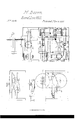
the city, county, and State of New York, have invented a new and Improved Sawmill for Sawing Any Description of Lumber from Logs, Gants, or Otherwise; and I do hereby declare that the following is a full and exact description thereof, reference being had to the annexed drawings, making a part of this specication, in which- Figure l, is a perspective view or ground plan; Fig. 2, a longitudinal elevation; Fig. 3, a transverse view; Fig. 4, a reverse view of Fig. 3; Fig. 5, a perspective view or ground plan of one of the carriages; Fig. 6, a transverse view of Fig. 5; A, the frame of the machine or mill; B, the saw mounted upon the pulleys, C, C; D, D', the driving pulleys; E, the counter shaft; F, the principal driving band; Gr, G, the transverse shafts; H, the ways; I, the carriages; K, the bands that move the carriages; L, a second counter shaft; M, the cog wheels connecting the shafts E, L; N, the plumber blocks; P, slides or friction rollers.
To enable others skilled in the art to make and use my invention I will proceed to describe its construction and operation.
I make a frame, A, proportioned in size and parts to the work to be performed, to which I attach the shafts bearing the pulleys, C, C', upon which the saw, B, is mounted. To the shaft, C, is attached the crank pulley or co wheel for driving the machine or sawmill y any motive power desired. This arrangement for driving can be attached-to either of the saw pulley shafts, to the driving pulleys marked, D, (straight and cone either at selection) to move the band F in connection with corresponding pulleys `marked, D', on the counter shaft, E. To this counter shaft are attached pulleys, a, a, and to another shaft, L, attached to the counter shaft E by the cog wheels, M, M, is attached pulleys, a, a, and also the transverse shafts, G, Gr, are attached to the bevel cog wheels, ZJ, b, b, and to these transverse shafts are attached pulleys, c, c. Above this arrangement of gearing and within the frame of my mill I attach the ways H, upon which the carriages, I,.I, are moved bearing the logs or timber to be sawed. These ways are made a parallelogram or long square varying according to the carriage or log to be sawed. They have outer and inner parallel bars connected at right angles. At the proper distances between these bars are placed pulleys CZ, cl, d, d, d, d, el, d. rIhe carriages I I (six in the model; the arrangement can be made for any number and to run inside or outside of the saw, as preferred) are made with a bed piece, in the under side of which the grooves are cut by which they are attached to and move on the bars of the ways, H, by means of the bands, K, having projections on them, moved by the pulleys, a, a, on the counter shaft; a a on the second counter shaft, and c, c, on the transverse shafts, over the pulleys CZ, d, d, al, d, d, CZ, d. The carriages have a top piece likewise and are connected by means of the pillars, e, e, e. At each end of the carriages are revolving dogs, f, connected with the pulley, g, by means of cords or chains, 7c, in such a manner as that when the log being prepared the right length and placed on the carriage between the dogs, f, the mill being in motion brings the carriage forward on the ways, H, until the pawl, L, (to which there is attached a ratchet wheel, r, and dogs for the purpose of moving and holding the pulley, g, to which it is attached) is brought in contact with the projection, i, by which means the pulley, g, is moved to the extent the projection, z', is in contact with the pawl, h, consequently by means of the cords or chains, le, the dogs f are moved in the 4same proportion, this arrangement constituting an exact principle of setting the log to the saw to make boards or planks of uniform thickness by means of the set screws, j, which operate upon the projection, i, at the will of the operator.
In constructing my saw, B, I make it of steel having holes in it at certain distances adapted to the circuit or length of my saw and the diameter of the pulleys over which it is to run, and in the pulleys I place projecting bolts or pins at such distances precisely to correspond with and meet the holes in the saw, and thus placing the saw on the pulleys, by means of the plumber block, N, and the set screws, O, passing the plumber blocks. I strain the saw to a suitable tension to perform its work. For the purpose of guiding the saw, I place friction rollers, P, next to the saw above and below where it passes through the log.
My mill in its operation is an endless saw receiving logs or timber to be sawed on successive carriages running on endless ways, and each log upon its carriage as it passes the projection, c', is set uniformly and thus the logs properly placed upon the carriages and the several parts of the mill in proper order. The Whole of the logs are cut up Without further labor of the operator, having only to remove the boards When saWed off, Which is done With great rapidity.
The advantages of this mill must be obvious to any observer.
I do not claim a saw or band running over pulleys Without reference to its construction and operation.
I claiml. The Ways, H, constructed substantially in the manner and for the purposes as herein set forth.
2. I claim the arrangement of gearing for the purpose of moving the carriages, I, I, I, I, I, I, on the Ways II substantially as set forth.
3. I claim the pulley, g, With its appendages of the paWl, L, and ratchet Wheel, 1', in
connection With the projection, z', and the dogs,lf, by means of the cords or chains, 7c, substantially in the manner and for the purposes described.
Ido not claim the projection, z', the dogs, f, or the chains, 7c, separately as they are not new and may be altered in their form in my mill and so used in connection with the pulley, g, and its appendage Which is my claim as above.
4. I claim the entire arrangement of my mill by Which a series of carriages are brought forward on endless Ways to an endless saw, and each log upon its carriage be ing accurately set as it passes the projection, i, and thereby securing accuracy, rapidity and eiciency substantially in the manner and for the purposes set forth.
y HARVEY BROWN.
Witnesses:
WILLIAM T. GRAFF, R. I-I. CUDLIPP.
Publications (1)
| Publication Number | Publication Date |
|---|---|
| US18570A true US18570A (en) | 1857-11-10 |
Family
ID=2081996
Family Applications (1)
| Application Number | Title | Priority Date | Filing Date |
|---|---|---|---|
| US18570D Expired - Lifetime US18570A (en) | Harvey brown |
Country Status (1)
| Country | Link |
|---|---|
| US (1) | US18570A (en) |
-
0
- US US18570D patent/US18570A/en not_active Expired - Lifetime
Similar Documents
| Publication | Publication Date | Title |
|---|---|---|
| US4009A (en) | Sawmill-carriage | |
| US18570A (en) | Harvey brown | |
| US26176A (en) | Sawmill | |
| US10778A (en) | Circular sawing machine | |
| US757626A (en) | Electrically-driven machine for sawing logs, &c. | |
| US933932A (en) | Railroad-tie sawmill. | |
| US9977A (en) | Sawmill | |
| US17112A (en) | purmort | |
| US20660A (en) | Method for clamping and laterally feeding the log in sawmills | |
| US16725A (en) | Cieculail-sawing mill | |
| US10705A (en) | Feed-motion foe | |
| US14909A (en) | Method oe operating- sawmill-blocks | |
| US160939A (en) | Improvement in sawing-machines | |
| US2531A (en) | Self-setting cog for sawmills | |
| US18269A (en) | Method of holding and setting logs in circular sawing machines | |
| US20696A (en) | Harvey brown | |
| US16241A (en) | Bokotg-machiite | |
| US10473A (en) | Sawmill | |
| US3287A (en) | Fob cross-sawietg timber | |
| US38264A (en) | Improvement in drag-saws | |
| US13043A (en) | Sawmill-door | |
| US4395A (en) | Sawmill | |
| US14220A (en) | Method of toughing and grooving tapering boards | |
| US23887A (en) | Machine for sawing shingles | |
| US356930A (en) | Band-saw mill |