US1857097A - Replaceable fuse element - Google Patents
Replaceable fuse element Download PDFInfo
- Publication number
- US1857097A US1857097A US331498A US33149829A US1857097A US 1857097 A US1857097 A US 1857097A US 331498 A US331498 A US 331498A US 33149829 A US33149829 A US 33149829A US 1857097 A US1857097 A US 1857097A
- Authority
- US
- United States
- Prior art keywords
- fuse element
- fuse
- sections
- replaceable
- slots
- Prior art date
- Legal status (The legal status is an assumption and is not a legal conclusion. Google has not performed a legal analysis and makes no representation as to the accuracy of the status listed.)
- Expired - Lifetime
Links
- 230000001788 irregular Effects 0.000 description 30
- 230000008018 melting Effects 0.000 description 24
- 238000002844 melting Methods 0.000 description 24
- 239000002184 metal Substances 0.000 description 12
- 210000002105 tongue Anatomy 0.000 description 2
- 102000012000 CXCR4 Receptors Human genes 0.000 description 1
- 108010061299 CXCR4 Receptors Proteins 0.000 description 1
- 230000015572 biosynthetic process Effects 0.000 description 1
- 238000007664 blowing Methods 0.000 description 1
- 238000010276 construction Methods 0.000 description 1
- 230000001066 destructive effect Effects 0.000 description 1
- 239000000463 material Substances 0.000 description 1
Images
Classifications
-
- H—ELECTRICITY
- H01—ELECTRIC ELEMENTS
- H01H—ELECTRIC SWITCHES; RELAYS; SELECTORS; EMERGENCY PROTECTIVE DEVICES
- H01H85/00—Protective devices in which the current flows through a part of fusible material and this current is interrupted by displacement of the fusible material when this current becomes excessive
- H01H85/02—Details
- H01H85/04—Fuses, i.e. expendable parts of the protective device, e.g. cartridges
- H01H85/05—Component parts thereof
- H01H85/055—Fusible members
- H01H85/08—Fusible members characterised by the shape or form of the fusible member
- H01H85/10—Fusible members characterised by the shape or form of the fusible member with constriction for localised fusing
Definitions
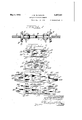
- Figure 1 is a fragmentary side elevation of the knife blade terminal unit of a knife blade 05 type cartridge fuse having mounted therein replaceable fuse elements embodying the principles of this invention.
- Figure 2 is a plan view of an improved replaceable fuse element of a type adapted to be mounted on the knife blade terminal units illustrated in Figure 1.
- Figure 3 is a plan view of a modified type of replaceable fuse element also adapted for use in cartridge fuses of the knife blade type.
- Figure 4 is a plan View of another modified form of large capacity replaceable fuse element adapted for use in-cartridge fuses of the knife blade type.
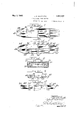
- Figure 5 is another modified form of replaceable fuse element for use in cartridge fuses of the knife blade type.
- Figure 6 illustrates another modified form of high capacity replaceable fuse element adapted for use in cartridge fuses of the knife blade type.
- Figure 7 is a plan view of another modifiedform of high capacity replaceable fuse element adapted for use in cartridge fuses of the knife blade type.
- Figure 8 is a longitudinal sectiontaken through a ferrule type cartridge fuse having mounted therein an improved replaceable fuse element embodying the principles of this invention.
- Figure 9 is a developed plan view of the 1 replaceable fuse element illustrated in Figure I 8 with said fuse element provided with l notches to clear the inner end of a fuse indicator mounted on the ferrule type tridge fuse.
- Figure 10 is a developed plan view of a modified form of higher ca acity replaceable fuse element adapted or use in cartridge fuses of the ferrule type.
- the reference numeral 1 indicates a pair of knife blade terminals of a cartridge fuse with said knifeblade terminals having the inner ends thereof reduced in width to form tongues or projections 2.
- a notched disk 3 Mounted oneach of the knife blade members 1 is a notched disk 3 and an outer metal disk 4.
- a stop plate or block 5 Secured on each knife blade 1 adjacent the inner surface of the notched disk 3 is a stop plate or block 5.
- Each of'the knife blade tongues 2 is provided with an aperture for the reception of a retaining bolt 6 or other suitable means for securing a single or a multiple type replaceable fuse strip or element in place between the knife blade terminal units of the cartridge fuse.
- Figure 1 illustrates the use of a double or multiple type replaceable fuse unit, the two fuseelements of which are provided with suitable apertures 7 provided in the middle portion of the fuse elements for the reception of connecting pins-or rivets 8 around which spacin sleeves 9 are engaged to hold the" replacea le fuse elements separated and in substantially parallel relation with one another.
- the improved replaceable fuse element adapted for use in the combination illustrated in Figure 1 comprises a strip of fusible metal embracing an intermediate or main body strip 10 having parallel longitudinal edges.
- the ends of the body strip 10 are shaped to form tapered end sections 11 the ends of which are squared at 12 to permit the same when engaged on knife blade termi nal units to abut against the stop plates or blocks 5 to-hold the replaceable fuse element inproper aligned position.
- Each end 11 of the replaceable fuse element is provided with a longitudinally directed notch 13 provided to permit the fuse element to be engaged around the bolts. 6 of the knife blade units.
- the body section 10 of the replaceable fuse element illustrated in Figure 2 is provided with the apertures 7 when the fuse element is to be used in multiple as illustrated in Figure 1. It will of course be understood that when the fuse element is to be used singly, the apertures 7 may be omitted.
- the body section 10 of the fuse element is also provided with a plurality of irregular slots or openings 14 of substantially I-shaped formation positioned in parallel relation transversely of the fuse' element so that the ends of the irregular slots 14 are parallel to the longitudinal edges of the body portion 10 of the replaceable fuse element.
- TlllS arrangement of the irregular openings 14 provides two pairs of parallel melting or fusing
- the body of the re- I placeable fuse element is substantially of equal width and cross section and is provided with the irregular slots or openings 14 which of course may be of any desired configuration other than the I-shape illustrated, provided that the slots afford fusing strips of sections15 along thelongitudinal edges of the body of the fuse element.
- This novel arrangement of a re laceable fuse element affords an element w ich may be easily and economically formed with the irregular 7 slots or openingsarranged to provide sets of oppositely positioned melting sections of a given or predetermined resistance whereby said fusing sections will melt on overloads or on short circuits, permitting the middle portion of the bod section 10 to drop away and separate from t e adjacent portions which remain connected to the knife blade units.
- Figure 3 covers a modified form of renewable fuse element and comprises a strip or main body section of fusible metal 16 of uniform width and having integrally formed on the ends thereof tapered ends or mounting sections 17 and 18 with the end section 17 provided with a longitudinally positioned end notch 19 while the tapered end section 18 is provided with a transversely positioned notch 20.
- the intermediate or main body section of the replaceable fuse element 16 is provided with a pair of apertures 21 adapted for use in connecting two or more re laceable fuse elements in parallel assemble relation to provide a multiple fuse unit. If desired, the apertures 21 may be omitted when the fuse element is to be used sin ly.
- the main body sections 16 of the fuse element illustrated in Figure 3 is provided with an irregular or H-shaped slot or'opening comprising a connecting slot or passage 22 disposed longitudinally in the center of the fuse element and connecting a pair of transverse slots 23, the ends of which are parallel and spaced from the longitudinal edges of the body section .16 of the fuse element to form melting or fuse strips 24 of a required length an cross section offering a predetermined resistance so that when the fuse element is subjected to an overload or to short circuits,
- replaceable fuse element of a higher capacity embraces afusible metal body section 25 of uniform width and having integrally formed on the ends thereof taperedend sections 26, each of which is provided with a central longitudinally directed notch 27 to facilitate mounting of the fuse elements.
- the ends of the tapered end sections 26 are squared at 28 to permit the replaceable fuse element to-be held in proper aligned position abutting against stop blocks 5 of the knife blade terminal units .of the kind illustrated in. Figure 1.
- the replaceable fuse element is to be used in multiple, 'the body section is provided with apertures 29 for the reception of pins or rivets used to connect parallel fuseelements.
- the main body section 25 of the fuse element is provided with transversely arranged irregular slots or openings 30 and 31, the ends of which are parallel to the longitudinal edges of the body section 25 and afford-pairs of parallel melting or fusing strips 32 and 33, with the fusing strips 33 being of greater cross section than the cross section of the fusing strips 32.
- the fusing strips 32 and 33 are formed of different cross section to provide different resistances by having the two irregular slots or openings31 shorter than the two outer ir- I regular slots 30.
- Figure 5 illustrates another modified form of replaceable fuse element embracing a body or intermediate section 34,0f uniform width having the ends thereof tapered to provide end sections 35 and 36.
- the end section 35 is provided with a longitudinal center notch .37 while the end section 36 is provided with a transverse notch 38.
- a rturs' 39 are provided in the middle portionof the body section 34 for the reception of rivets or pins when the element is to be used in multiple.
- the main body portion 34 of the fuse element is provided with a plurality of H-shaped irregular openings on opposite sides of the apertures 39 and each comprising a longitudinally positioned middle or connecting slot 40 connecting a pair of transverse slots or openings 41 and 42 with the transverse slot 42 shorter than the transverse slot 41.
- the two transverse slots have the ends thereof parallel to the longitudinal edges of the body section 34 thereby providing two pairs of melting or fusing strips 43 and 44 of different cross sections and of different resistgrally formed on the ends thereof ltapered v end sections 46 provided with longitudinally disposed end notches 47.
- 'Small apertures 48 are provided. in the body section for the reception of rivets or pins when the fuse are to be used in multiple.
- Proelements vided in the middle portion of the body section 45 is a transverse irregular or Z-shaped I slot or opening 49, the end portions of which project in opposite directions and are spaced and parallel to the longitudinal edges of the body section 45 to afford primary melting or fusing strips 50.
- transversely positioned channel or U-shaped transversely disposed irregular slots or openings 51 are provided in the body section 45 near the end sections 46 .
- secondary melting 'or fusing sections 52 which are smaller in cross section than the melting or fusing sections 50.
- the primary meltmg sections 50 will melt or blow creating a gap in the middle portion of the body section 45.
- both the primary andrtlre secondary melting sections 50 and 52 will melt or blow permitting a plurality of drop out sections to fall out to insure positive breaking of the circuit.
- Figure 7 illustrates another modified form of renewable fuse element comprising a strip of fusible metal consisting of a body section 53 of uniform width having integrally formed on the ends thereof tapered end sections 54 and 55 rovided with notches 56 and 57 respective y.
- the body section 53 is provided with a plurality of small apertures 58, two-diagonally positioned apertures adapted to be provided with rivets or pins when the fuse elements are used in multiple. When the fuse element is used singly, the apertures 58 may be omitted.
- the body section 53 is provided with an irregular slot or openin comprising a transversely positioned mi dle or intermediate irregular slot or I-shaped opening 59 connected by longitudinally positioned connectirregular slots 61 are longer than the middle transverse slot 59 and have the ends thereof fuse strips 7 8.
- the end portions of the fuse positioned adjacent and parallel to the longitudinal edges of the body section 53 to afford secondary fusing or melting sections 62 while the ends of the middle irregular slot 59 are also disposed parallel to the longitudinal edges of the body section 53 and afford primary melting sections or-strips 63 which are of greater cross section than the cross section of the melting sections. 62.
- Figure 8 illustrates a longitudinal section of a cartridge fuse of the ferrule type comprising a cylindrical body 64 having radially engaged in the wall thereof a fuse indicator 65.
- e body section 64 is provided with slotted thimble plates 66 and 67 through which the end sections 68 of a metal fuse strip 69 are adapted to be projected and bent over to form a Z-shaped element.
- Retaining heads 70 are engaged against the ends 68 of the fuse element and are secured in place by internally threaded locking rings 71 or the like.
- the body portion of the replaceable fuse element 69' is provided with a pair of oppositely positioned notches 7 2 whereby the inner end of the fuse indicator 65 is adapted to be properly cleared when the replaceable fuse element is mounted in position within the ferrule type cartridge fuse.
- a transversely positioned irregular slot or opening 73 having the end portions of said slot posi tioned parallel to the longitudinal edges of the body section 69 to afford melting or fusingstrips 74 which are adapted to melt or fuse when the fuse element is subjected to overloads or to short circuits thereby permitting the middle portion of the body section 69 to drop out to insure proper breaking of the circuit.
- Figure 10 illustrates a developed plan view of a modified form of replaceable fuse element adapted for use in cartridge fuses of the ferrule type and embraces a body section of uniform width'with said body section-75 pro-- vided with a pluralityof transversely positioned irregular slots or openings 76 and 7 7" with the slots 77 being longer than the slots 76 and having the ends thereof positioned par-- allel to the longitudinal edges of the body strip 75 to afford primary fusing strips 78.
- the irregular slots 76 are shorter than the irregular slots 77 and have 'the ends thereof positioned parallelto the longitudinal edges of the body section 75 to provide a plurality of secondary melting or fuse strips 79 which are of a greater cross section than the primary element are provided with transverse creases or grooves 80 permitting the rounded end sections 81 of the fuse element to be bent over in opposite directions to permit mounting of a fuse element within a ferrule type cartridge fuse.
- the primary melting strips 78 are adapted to melt to permit the portion of the fuse element between the irregular slots 77 to drop out.
- both the primary and secondary illustrated and described in which the elements are of substantially the same width except for the tapered end sections and are provided with irregular slots or openings of various shapes permitting melting or fusing strips to be formed in the mainbody of the fuse elements parallel to the longitudinal edges of the elements whereby when the elements are subjected to overloads or short circuits, a positive breaking of the circuit is insured due to the blowing of the primary or the primary and secondary fusing strips topermit sections of the fuse elements to drop out to insure a gap between the end portions 'of the fuse elements which are secured to the terminal heads or units of the cartridge fuses in which-the fuse element may be mounted.
- the rovision of irregular slots or openings in a use element permits the-fuse element to'be constructed of substantially a uniform width thereby providing a strong element which may be readil manufactured at. economical cost and whic furthermore permits the element to be provided with the required melting or fusing strips of the same or different cross sections andresistances to insure positive dropping out of the intermediate section or sections of the fuse element when said element is subjected to overloads or to short circuits.
- the various fuse elements illustrated and described may be used singly or in multi le as illustrated in Figure 1 and it will a so be noted that the elements may be adapted for use in cartridge fuses of the knife blade t e or in cartridge fuses of the ferrule type.
- a replaceable fuse element comprising a fusible metal strip having an irregular opening therein forming aligned melting sections 2 of different resistances.
- a replaceable fuse element comprising a fusible metal strip having the ends thereof formed to permit the strip to be mounted in position in a cartridge type fuse, said fusible 3 metal strip having irregular slots of different lengths formed therein with the ends of said slots wider than the main portion of the slots and positioned parallel to the longitudinal edges of the fusible metal strip to form melt- 5 ing sections of different resistances.
- a fuse element comprising a fusible metal strip having transverse slots of different lengths therein to form aligned melting sections of different resistances.
Landscapes
- Fuses (AREA)
Description
y 3, 1932- J. B. GLOWACKI 7,097
REPLACEABLE FUSE ELEMENT Filed Jan. 10, 1929 2 Sheets-Sheet l y 1932- J. B. GLOWACKE 7 REPLACEABLE FUS E ELEMENT Filed Jan. 10, 1929 2 Sheets-Sheet 2 Patented May 3, 1932 PATENT OFFICE- JOHN B. GLOWACKI, or CHICAGO, ILLmoIs nnrmcmm ruse Ema Application filed January 10, 1929. Serial no. 331,493.
fuses of the knife blade cartridge type, said.
6 fuse elements adapted to be interposed in electric circuits toprevent destructive action of the current due to overloading or short circuits.
It is an object of this invention to provide 10 a replaceable fuse element constructed of a strip of metal having one or more irregular openings or slots provided therein with portions of the slots positioned parallel to the longitudinal edges of the fuse strip to afford 1 fusing sections of a predetermined resistance whereby upon overloadin .or short circuiting I of the fuse element, the %using sections will blow, thereby creating a drop out portion adapted to interrupt the circuit.
It is also an object of this invention to provide an improved. replaceable fuse element constructed of substanti'allya straight strip of material having irregular openings in the portion of greatest .cross section affording fusing strips of uniform cross section parallel to thelongitudinal edges of the element to afford a drop-out section between the ends of the fuse element when the elementis subjected to overloads or short circuits.
It is a further object of this invention to rovide a replaceable fuse element wherein irregular slots or openings are provided either longitudinally or transversely of the element to afford parallel fusin strips of a predetermined resistance with t e strips ar ranged in airs of equal cross section or in pairs of different cross sections de nding upon whether the element is intende for u se in a small capacity fuse or in a high capacity fuse. a
It is furthermore an object of this invention to provide a replaceable fuse element adapted for use in ferrule type cartridge fuses or in cartridge fuses of the knife blade type and having irregular slots arranged therein with the ends of-the slots arranged in parallel relation to afl'ord parallel melting strips of equal or diiferent cross sections. 1
It is an important object of this invention to provide a replaceable fuse element wherein drop out sections are adapted to be created by arranging irregular openings in grouped relation to afford pairs of mounting strips of equal or unequal cross section parallel to the v longitudinal edges of the fuse element.
Other and further important objects of this invention will be apparent from the disclosures in the specification and the accompanying drawings.
This invention (in a preferred form) is illustrated in the drawings and hereinafter more fully described. J
On the drawings: I
Figure 1 is a fragmentary side elevation of the knife blade terminal unit of a knife blade 05 type cartridge fuse having mounted therein replaceable fuse elements embodying the principles of this invention. a
Figure 2 is a plan view of an improved replaceable fuse element of a type adapted to be mounted on the knife blade terminal units illustrated in Figure 1.
Figure 3 is a plan view of a modified type of replaceable fuse element also adapted for use in cartridge fuses of the knife blade type.
Figure 4 is a plan View of another modified form of large capacity replaceable fuse element adapted for use in-cartridge fuses of the knife blade type.
Figure 5 is another modified form of replaceable fuse element for use in cartridge fuses of the knife blade type.
Figure 6 illustrates another modified form of high capacity replaceable fuse element adapted for use in cartridge fuses of the knife blade type. i
Figure 7 is a plan view of another modifiedform of high capacity replaceable fuse element adapted for use in cartridge fuses of the knife blade type. l
Figure 8 is a longitudinal sectiontaken through a ferrule type cartridge fuse having mounted therein an improved replaceable fuse element embodying the principles of this invention.
Figure 9 is a developed plan view of the 1 replaceable fuse element illustrated in Figure I 8 with said fuse element provided with l notches to clear the inner end of a fuse indicator mounted on the ferrule type tridge fuse.
Figure 10 is a developed plan view of a modified form of higher ca acity replaceable fuse element adapted or use in cartridge fuses of the ferrule type.
As shown on the drawings:
The reference numeral 1 indicates a pair of knife blade terminals of a cartridge fuse with said knifeblade terminals having the inner ends thereof reduced in width to form tongues or projections 2. Mounted oneach of the knife blade members 1 is a notched disk 3 and an outer metal disk 4. Secured on each knife blade 1 adjacent the inner surface of the notched disk 3 is a stop plate or block 5. Each of'the knife blade tongues 2 is provided with an aperture for the reception of a retaining bolt 6 or other suitable means for securing a single or a multiple type replaceable fuse strip or element in place between the knife blade terminal units of the cartridge fuse. Figure 1 illustrates the use of a double or multiple type replaceable fuse unit, the two fuseelements of which are provided with suitable apertures 7 provided in the middle portion of the fuse elements for the reception of connecting pins-or rivets 8 around which spacin sleeves 9 are engaged to hold the" replacea le fuse elements separated and in substantially parallel relation with one another.
The improved replaceable fuse element adapted for use in the combination illustrated in Figure 1 comprises a strip of fusible metal embracing an intermediate or main body strip 10 having parallel longitudinal edges. The ends of the body strip 10 are shaped to form tapered end sections 11 the ends of which are squared at 12 to permit the same when engaged on knife blade termi nal units to abut against the stop plates or blocks 5 to-hold the replaceable fuse element inproper aligned position. Each end 11 of the replaceable fuse element is provided with a longitudinally directed notch 13 provided to permit the fuse element to be engaged around the bolts. 6 of the knife blade units.
The body section 10 of the replaceable fuse element illustrated in Figure 2 is provided with the apertures 7 when the fuse element is to be used in multiple as illustrated in Figure 1. It will of course be understood that when the fuse element is to be used singly, the apertures 7 may be omitted.
The body section 10 of the fuse element is also provided with a plurality of irregular slots or openings 14 of substantially I-shaped formation positioned in parallel relation transversely of the fuse' element so that the ends of the irregular slots 14 are parallel to the longitudinal edges of the body portion 10 of the replaceable fuse element. TlllS arrangement of the irregular openings 14 provides two pairs of parallel melting or fusing It will be noted that the body of the re- I placeable fuse element is substantially of equal width and cross section and is provided with the irregular slots or openings 14 which of course may be of any desired configuration other than the I-shape illustrated, provided that the slots afford fusing strips of sections15 along thelongitudinal edges of the body of the fuse element. This novel arrangement of a re laceable fuse element affords an element w ich may be easily and economically formed with the irregular 7 slots or openingsarranged to provide sets of oppositely positioned melting sections of a given or predetermined resistance whereby said fusing sections will melt on overloads or on short circuits, permitting the middle portion of the bod section 10 to drop away and separate from t e adjacent portions which remain connected to the knife blade units.
Figure 3 covers a modified form of renewable fuse element and comprises a strip or main body section of fusible metal 16 of uniform width and having integrally formed on the ends thereof tapered ends or mounting sections 17 and 18 with the end section 17 provided with a longitudinally positioned end notch 19 while the tapered end section 18 is provided with a transversely positioned notch 20. The intermediate or main body section of the replaceable fuse element 16 is provided with a pair of apertures 21 adapted for use in connecting two or more re laceable fuse elements in parallel assemble relation to provide a multiple fuse unit. If desired, the apertures 21 may be omitted when the fuse element is to be used sin ly. The main body sections 16 of the fuse element illustrated in Figure 3 is provided with an irregular or H-shaped slot or'opening comprising a connecting slot or passage 22 disposed longitudinally in the center of the fuse element and connecting a pair of transverse slots 23, the ends of which are parallel and spaced from the longitudinal edges of the body section .16 of the fuse element to form melting or fuse strips 24 of a required length an cross section offering a predetermined resistance so that when the fuse element is subjected to an overload or to short circuits,
of replaceable fuse element of a higher capacity and embraces afusible metal body section 25 of uniform width and having integrally formed on the ends thereof taperedend sections 26, each of which is provided with a central longitudinally directed notch 27 to facilitate mounting of the fuse elements. ,The ends of the tapered end sections 26 are squared at 28 to permit the replaceable fuse element to-be held in proper aligned position abutting against stop blocks 5 of the knife blade terminal units .of the kind illustrated in. Figure 1. When the replaceable fuse element is to be used in multiple, 'the body section is provided with apertures 29 for the reception of pins or rivets used to connect parallel fuseelements. The main body section 25 of the fuse element is provided with transversely arranged irregular slots or openings 30 and 31, the ends of which are parallel to the longitudinal edges of the body section 25 and afford-pairs of parallel melting or fusing strips 32 and 33, with the fusing strips 33 being of greater cross section than the cross section of the fusing strips 32. The fusing strips 32 and 33 are formed of different cross section to provide different resistances by having the two irregular slots or openings31 shorter than the two outer ir- I regular slots 30. When the replaceable fuse element illustrated in Figure 4 is subjected to an overload, the melting sections 33 will blow or melt thereby permitting the middle portion of the body section 25 to dropout rom between the portions of the body section between the slots 30 and 31. When the fuse element is subjected to a short circuit all of the fusing strips 32 and 33 will blow or melt thereby ermitting three dro out sections to fall rom between the en sections 26 to interrupt the circuit.
Figure 5 illustrates another modified form of replaceable fuse element embracing a body or intermediate section 34,0f uniform width having the ends thereof tapered to provide end sections 35 and 36. The end section 35 is provided with a longitudinal center notch .37 while the end section 36 is provided with a transverse notch 38. A rturs' 39 are provided in the middle portionof the body section 34 for the reception of rivets or pins when the element is to be used in multiple. The main body portion 34 of the fuse element is provided with a plurality of H-shaped irregular openings on opposite sides of the apertures 39 and each comprising a longitudinally positioned middle or connecting slot 40 connecting a pair of transverse slots or openings 41 and 42 with the transverse slot 42 shorter than the transverse slot 41. The two transverse slots have the ends thereof parallel to the longitudinal edges of the body section 34 thereby providing two pairs of melting or fusing strips 43 and 44 of different cross sections and of different resistgrally formed on the ends thereof ltapered v end sections 46 provided with longitudinally disposed end notches 47. 'Small apertures 48 are provided. in the body section for the reception of rivets or pins when the fuse are to be used in multiple. Proelements vided in the middle portion of the body section 45 is a transverse irregular or Z-shaped I slot or opening 49, the end portions of which project in opposite directions and are spaced and parallel to the longitudinal edges of the body section 45 to afford primary melting or fusing strips 50. Provided in the body section 45 near the end sections 46 are transversely positioned channel or U-shaped transversely disposed irregular slots or openings 51, the ends of which are parallel toone another and to the longitudinal edges of the body section 45 to provide. secondary melting 'or fusing sections 52 which are smaller in cross section than the melting or fusing sections 50. When the fuse element is subjected to overloads, theprimary meltmg sections 50 will melt or blow creating a gap in the middle portion of the body section 45. When the fuse element is subjected to a short circuit, both the primary andrtlre secondary melting sections 50 and 52 will melt or blow permitting a plurality of drop out sections to fall out to insure positive breaking of the circuit.
Figure 7 illustrates another modified form of renewable fuse element comprising a strip of fusible metal consisting of a body section 53 of uniform width having integrally formed on the ends thereof tapered end sections 54 and 55 rovided with notches 56 and 57 respective y. The body section 53 is provided with a plurality of small apertures 58, two-diagonally positioned apertures adapted to be provided with rivets or pins when the fuse elements are used in multiple. When the fuse element is used singly, the apertures 58 may be omitted.
The body section 53 is provided with an irregular slot or openin comprising a transversely positioned mi dle or intermediate irregular slot or I-shaped opening 59 connected by longitudinally positioned connectirregular slots 61 are longer than the middle transverse slot 59 and have the ends thereof fuse strips 7 8. The end portions of the fuse positioned adjacent and parallel to the longitudinal edges of the body section 53 to afford secondary fusing or melting sections 62 while the ends of the middle irregular slot 59 are also disposed parallel to the longitudinal edges of the body section 53 and afford primary melting sections or-strips 63 which are of greater cross section than the cross section of the melting sections. 62. On an.
overload to the fuse element, the primary melting sections 63 will blow creating a gap in the body section 53. When the fuse element is subjected to a short circuit, both the primary and secondary melting strips 63 and 62 will blow to insure positive breaking of the circuit and falling out of the drop out sections. V
Figure 8 illustrates a longitudinal section of a cartridge fuse of the ferrule type comprising a cylindrical body 64 having radially engaged in the wall thereof a fuse indicator 65. e body section 64 is provided with slotted thimble plates 66 and 67 through which the end sections 68 of a metal fuse strip 69 are adapted to be projected and bent over to form a Z-shaped element. Retaining heads 70 are engaged against the ends 68 of the fuse element and are secured in place by internally threaded locking rings 71 or the like. The body portion of the replaceable fuse element 69'is provided with a pair of oppositely positioned notches 7 2 whereby the inner end of the fuse indicator 65 is adapted to be properly cleared when the replaceable fuse element is mounted in position within the ferrule type cartridge fuse. Provided in each end portion of the fuse element 69 near the notches 72 is a transversely positioned irregular slot or opening 73 having the end portions of said slot posi tioned parallel to the longitudinal edges of the body section 69 to afford melting or fusingstrips 74 which are adapted to melt or fuse when the fuse element is subjected to overloads or to short circuits thereby permitting the middle portion of the body section 69 to drop out to insure proper breaking of the circuit.
Figure 10 illustrates a developed plan view of a modified form of replaceable fuse element adapted for use in cartridge fuses of the ferrule type and embraces a body section of uniform width'with said body section-75 pro-- vided with a pluralityof transversely positioned irregular slots or openings 76 and 7 7" with the slots 77 being longer than the slots 76 and having the ends thereof positioned par-- allel to the longitudinal edges of the body strip 75 to afford primary fusing strips 78.
The irregular slots 76 are shorter than the irregular slots 77 and have 'the ends thereof positioned parallelto the longitudinal edges of the body section 75 to provide a plurality of secondary melting or fuse strips 79 which are of a greater cross section than the primary element are provided with transverse creases or grooves 80 permitting the rounded end sections 81 of the fuse element to be bent over in opposite directions to permit mounting of a fuse element within a ferrule type cartridge fuse. When a fuse element of the class illustrated in Figure 10 is subjected to an over-' load, the primary melting strips 78 are adapted to melt to permit the portion of the fuse element between the irregular slots 77 to drop out. When the fuse element is subjected to a short circuit, both the primary and secondary illustrated and described in which the elements are of substantially the same width except for the tapered end sections and are provided with irregular slots or openings of various shapes permitting melting or fusing strips to be formed in the mainbody of the fuse elements parallel to the longitudinal edges of the elements whereby when the elements are subjected to overloads or short circuits, a positive breaking of the circuit is insured due to the blowing of the primary or the primary and secondary fusing strips topermit sections of the fuse elements to drop out to insure a gap between the end portions 'of the fuse elements which are secured to the terminal heads or units of the cartridge fuses in which-the fuse element may be mounted. The rovision of irregular slots or openings in a use element permits the-fuse element to'be constructed of substantially a uniform width thereby providing a strong element which may be readil manufactured at. economical cost and whic furthermore permits the element to be provided with the required melting or fusing strips of the same or different cross sections andresistances to insure positive dropping out of the intermediate section or sections of the fuse element when said element is subjected to overloads or to short circuits. The various fuse elements illustrated and described may be used singly or in multi le as illustrated in Figure 1 and it will a so be noted that the elements may be adapted for use in cartridge fuses of the knife blade t e or in cartridge fuses of the ferrule type. 0 vapertured reduced sections are therefore necessar in this type of replaceable fuse element there y obviating the use of weak sections included in many types of earlier fuse elements. The provision of irregular slots or openings in the fuse elements of uniform width affords an improved means for providing the necesare subjected to overloads and short circuits.
While tapered square ended and round ended end sections are illustrated and described in connection with the various types 5 of replaceable fuse elements, it will, of course, be understood that any desired or required type of end portions may be formed on the improved renewable fuse elements so long as the body portions of the element are provided 1 with the irregular slots or openings required to afford primary and secondary melting or fusing strips hereinbefore described.
It will, of course, be understood that many changes may be made and numerous details 1 of construction may be varied through a wide range Without departing from the principles of this invention and, it is, therefore, not purposed limiting the patent granted hereon otherwise than necessitated by the scope of the appended claims.
I claim as my invention 1. A replaceable fuse element comprising a fusible metal strip having an irregular opening therein forming aligned melting sections 2 of different resistances.
2. A replaceable fuse element comprising a fusible metal strip having the ends thereof formed to permit the strip to be mounted in position in a cartridge type fuse, said fusible 3 metal strip having irregular slots of different lengths formed therein with the ends of said slots wider than the main portion of the slots and positioned parallel to the longitudinal edges of the fusible metal strip to form melt- 5 ing sections of different resistances.
3. A fuse element comprising a fusible metal strip having transverse slots of different lengths therein to form aligned melting sections of different resistances.
In testimony whereof I have hereunto subscribed my name at Chicago, Cook County,
Illinois.
JOHN B. GLOWACKI.
Priority Applications (1)
| Application Number | Priority Date | Filing Date | Title |
|---|---|---|---|
| US331498A US1857097A (en) | 1929-01-10 | 1929-01-10 | Replaceable fuse element |
Applications Claiming Priority (1)
| Application Number | Priority Date | Filing Date | Title |
|---|---|---|---|
| US331498A US1857097A (en) | 1929-01-10 | 1929-01-10 | Replaceable fuse element |
Publications (1)
| Publication Number | Publication Date |
|---|---|
| US1857097A true US1857097A (en) | 1932-05-03 |
Family
ID=23294216
Family Applications (1)
| Application Number | Title | Priority Date | Filing Date |
|---|---|---|---|
| US331498A Expired - Lifetime US1857097A (en) | 1929-01-10 | 1929-01-10 | Replaceable fuse element |
Country Status (1)
| Country | Link |
|---|---|
| US (1) | US1857097A (en) |
Cited By (6)
| Publication number | Priority date | Publication date | Assignee | Title |
|---|---|---|---|---|
| US2489501A (en) * | 1945-05-30 | 1949-11-29 | Economy Fuse And Mfg Company | Fuse link |
| US2720567A (en) * | 1953-05-15 | 1955-10-11 | Detch Lewis | Cartridge fuse fusible element |
| US3171924A (en) * | 1962-08-07 | 1965-03-02 | Chelsea Products Incorporate | Fuse controlled safety disconnect switch |
| US4349802A (en) * | 1981-01-08 | 1982-09-14 | Mcgraw-Edison Company | Current limiting fuse having transverse parallel weak spots |
| US5254967A (en) * | 1992-10-02 | 1993-10-19 | Nor-Am Electrical Limited | Dual element fuse |
| US5355110A (en) * | 1992-10-02 | 1994-10-11 | Nor-Am Electrical Limited | Dual element fuse |
-
1929
- 1929-01-10 US US331498A patent/US1857097A/en not_active Expired - Lifetime
Cited By (6)
| Publication number | Priority date | Publication date | Assignee | Title |
|---|---|---|---|---|
| US2489501A (en) * | 1945-05-30 | 1949-11-29 | Economy Fuse And Mfg Company | Fuse link |
| US2720567A (en) * | 1953-05-15 | 1955-10-11 | Detch Lewis | Cartridge fuse fusible element |
| US3171924A (en) * | 1962-08-07 | 1965-03-02 | Chelsea Products Incorporate | Fuse controlled safety disconnect switch |
| US4349802A (en) * | 1981-01-08 | 1982-09-14 | Mcgraw-Edison Company | Current limiting fuse having transverse parallel weak spots |
| US5254967A (en) * | 1992-10-02 | 1993-10-19 | Nor-Am Electrical Limited | Dual element fuse |
| US5355110A (en) * | 1992-10-02 | 1994-10-11 | Nor-Am Electrical Limited | Dual element fuse |
Similar Documents
| Publication | Publication Date | Title |
|---|---|---|
| US1857097A (en) | Replaceable fuse element | |
| US3148257A (en) | Electric fuses | |
| US2809257A (en) | Composite fuse links of silver and copper | |
| US2866037A (en) | Electric current limiting fuse | |
| US2658974A (en) | High current carrying capacity current-limiting fuses | |
| US2502747A (en) | Electric fuse | |
| US2670418A (en) | Fuse and fuse holder | |
| US1857098A (en) | Renewable fuse element | |
| US1815233A (en) | Terminal block | |
| US2181825A (en) | Electric fuse | |
| US1950489A (en) | Cartridge fuse, knife blade type | |
| US2028720A (en) | Fusible link | |
| US2489501A (en) | Fuse link | |
| US1952279A (en) | Fuse plug for electric light switch boxes | |
| DE1943231C3 (en) | Electrical load switch | |
| US3611239A (en) | High-voltage fuse having inner core and outer shell fuse links | |
| US2028721A (en) | Fusible link | |
| US2858396A (en) | Electric fuses | |
| US3194923A (en) | Current limiting fuse | |
| US2234026A (en) | Street lamp puller | |
| USRE18886E (en) | Renewable fuse element | |
| US3714613A (en) | Canted fuse element | |
| US1573392A (en) | Renewable fuse element | |
| USRE18128E (en) | Renewable fuse element | |
| US1396255A (en) | Fuse or cut-out |