US1857090A - Valve reseating tool - Google Patents
Valve reseating tool Download PDFInfo
- Publication number
- US1857090A US1857090A US370265A US37026529A US1857090A US 1857090 A US1857090 A US 1857090A US 370265 A US370265 A US 370265A US 37026529 A US37026529 A US 37026529A US 1857090 A US1857090 A US 1857090A
- Authority
- US
- United States
- Prior art keywords
- tool spindle
- caps
- threaded
- tool
- valve
- Prior art date
- Legal status (The legal status is an assumption and is not a legal conclusion. Google has not performed a legal analysis and makes no representation as to the accuracy of the status listed.)
- Expired - Lifetime
Links
- 238000010276 construction Methods 0.000 description 3
- 239000002184 metal Substances 0.000 description 2
- 238000012986 modification Methods 0.000 description 2
- 230000004048 modification Effects 0.000 description 2
- 101100379079 Emericella variicolor andA gene Proteins 0.000 description 1
- 238000000034 method Methods 0.000 description 1
- 230000000717 retained effect Effects 0.000 description 1
Images
Classifications
-
- B—PERFORMING OPERATIONS; TRANSPORTING
- B23—MACHINE TOOLS; METAL-WORKING NOT OTHERWISE PROVIDED FOR
- B23C—MILLING
- B23C3/00—Milling particular work; Special milling operations; Machines therefor
- B23C3/02—Milling surfaces of revolution
- B23C3/05—Finishing valves or valve seats
-
- Y—GENERAL TAGGING OF NEW TECHNOLOGICAL DEVELOPMENTS; GENERAL TAGGING OF CROSS-SECTIONAL TECHNOLOGIES SPANNING OVER SEVERAL SECTIONS OF THE IPC; TECHNICAL SUBJECTS COVERED BY FORMER USPC CROSS-REFERENCE ART COLLECTIONS [XRACs] AND DIGESTS
- Y10—TECHNICAL SUBJECTS COVERED BY FORMER USPC
- Y10T—TECHNICAL SUBJECTS COVERED BY FORMER US CLASSIFICATION
- Y10T408/00—Cutting by use of rotating axially moving tool
- Y10T408/55—Cutting by use of rotating axially moving tool with work-engaging structure other than Tool or tool-support
- Y10T408/557—Frictionally engaging sides of opening in work
- Y10T408/558—Opening coaxial with Tool
- Y10T408/5587—Valve fitting
Landscapes
- Engineering & Computer Science (AREA)
- Mechanical Engineering (AREA)
- Prostheses (AREA)
Description
Filed June 12, 1929 3 m .w T lf2 m W I@ ,147@ 70 W. JH x #y j I 7M Y B x 3 l l 4. 3 1a ..102 d 1.,] 11m l t] ,A v www.
3 4 6 7m ,y E
Patented May 3, 1932 JonN TEKAVEG, on CLEVELAND,
OHIO, AssIGNoR 4on yONE-HALF To L. D. FAERELL, or
CLEVELAND, oHIo f VALVE vRESEATING rrooL Application filed June 12,
This invention relates to improvements in valve reseating tools, an object of the invention being to provide a tool which is prima-V rily designed to facilitatethe reseating of 5 valves, faucets and the like, with ease and despatch. Y An object of this invention therefore is, to provide a tool which will be applicable to valve-casings, and the like, of a variety of 1o sizes, either-externally or internally threaded.
Another object is to provide a tool, which will be simple and practical in construction, strong and durable and ellicient in use, and comparatively inexpensive to make.
The foregoing and other objects, together with their attendant advantages, will be apparent as the invention becomes better understood, by reference to the accompanying specification and drawings forming a part thereof, it being premised that changes may be made in the various details and manner of operation, Within the scope of the appended claims, without-.departing from the spirit of the invention.
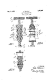
An example of my invention is illustrated in the accompanying drawings in which Figure l is a central vertical section. Figure 2 is a side view in elevation. Figure 3 is a view corresponding to Fig. l,
. of a slightly modified form, showing a converse arrangement of securing the caps.
In the said drawings a indicates an adapting device of any suitable form internallythreaded and tapered or otherwise asatal, Y
adapted to engage various sizes of eXteriorly threaded valve casings and the like, and having formed thereon or `attached thereto, or Y integral therewith, a hub a2, having an 'annular groove a3, and having a hole or bore at therethrough snugly engaging the tool spindle. Y
b is a cap member, mutually formed to rotatably lit the hub and annular groove, and having a threaded bore .b1 to threadedly engage the tool spindle. Thecap is also formed with an integraLboss b2 having a friction surface b3, and a knurled section b4, their purposes are hereinafter described.
0 indicates an adapting device, of any suitable form, externally threaded and tapered or 1929. seriai No. 370,265.
otherwise as at 01, adapted to engage various sizes of interiorly threaded valve casings and the like, and having formed thereon o r attached thereto or integral therewith, ya hub c2, having anv annular groove c3, and having a holek or bore c4 therethrough snugl'yengaging the tool spindle.
' d is acap member mutually formed'V to ro` tatablyht the hub and annular groove, and having'a threadedbore d1 to threadedly engage the tool spindle. The cap is also formed with `an'integral boss Z2 having a friction surface d3, land a knurled section d, their purposes are hereinafter described; 1'
e indicates an adapting device, of any: suitable form, havingy an annular skirt el terminating in an `internally projecting flange e2, having a ycap f mutually formed to lit rotatably thel skirt and flange, otherwise the construction is-the same as that of a and b above described. K
g indicates an adaptingdevice of any suitable form, having an annular skirt g1 and terz' indicatesa threadedtool spindle havingv its ends similarly reduced in diameter to form a shoulder and beingthreaded as at il and 2 to reversibly receive the actuating means jor the cutter 7c. f
jindicates a detachablfemounted actuating device havinga threaded axial bore jl to engage the -tool spindle on either end.
7c indicates adetachably mounted cutter having a threaded bore k1 to engage the tool spindle on either end.
It is evident from the construction as shown, that. the cap will not'fit on 0r over the hub, or on or into'the skirt formed on the adapting device, due to the flange formed thereon or therein. This is accomplished by splitting the cap as at @,a" and y, y, the skirt may be .likewise split (not shown but understood in the art), the metal is thendistended inl order that the flange may be made to encompass the hub on the device, or the skirt likewise distended to encompass the an nular groove on the cap; the distended portions are then forced back to place, and the threaded tool spindle With its cutter -is-` brought into cutting relation Withthe valve j seat through the operation of the actuating means. The knurled portions of the caps are grasped, one in each hand. kOne cap is held stationary andthe other'isturned down on the threadedtoolspindle. The contiguous ends4 ofthel bosses on the caps engage one another'frctionally and act as aloclzingdevice o-r as lock nuts, thereby holding the tool spindle rigid in the caps,.but allovvingthe tool spindle to rotate onl the hub of the device or in the skirt, which ever method is used.
If/itbe found necessary to remove additional' metal fromthe valve seat, the caps are loosened on the tool spindle, the cap held in one hand, andA the' vtool spindle threaded slightly into the cap downwardly, the caps are-again locked, both of said caps being -rotationally free relative tofsaidl adapting devices, and the operation repeated, until the result desired is obtained.
While I have herein shown and -described one. example of my invention, itwill be readily understood lthat changes and modifica-tions therein may be found desirable or essential in meeting the various exigencies Yof use, and
I desire to be understood as reserving the Aright to make any and all such changes-or V,modifications as may be found desirable or essenti-aL-in so far as the same may falfl With- Y in the spirit and scope of the invention as expressed in the accompanying claims when broadly construed.
-Having thus described my invention, what .I claim is l. A valve reseating device comprising a threaded tool spindle equipped With reversibly'mounted actuating means and cutter, the tool spindle also having threaded adapting devicesmounted thereon, each device having an axialbo-red annular grooved hub ,rotatably mounted bossed caps with locking surfaces and axial aligned bores, secured to each adapting device, and. means in the caps to position the tool spindle.
.2. A valve reseating device comprising a threaded tool spindle equipped With reversibly mounted actuating means and cutter, the tool spindle also having adapting devices Ymounted thereon, one of the said devices beinrg interiorly tapered and threaded, the other Y being exteriorly tapered and threaded, each f member having an axial bored annular grooved hub; rotatably mounted bossed caps' With locking surfaces and axial aligned bores secured to each adapting device, and means in the caps to position the tool spindle.
3. A valve reseating device comprising a threaded tool spindle equipped with reversibly mounted Vactin-.ating means and cutter, the toolrspindle also havingthreaded adapting devices mounted thereon, each device having an axialboreand anI annular flanged skirt, rotatably mounted bossed caps With locking surfaces and axial aligned bores, secured'to each adapting device, means in the caps vvvherebyrthe position of the tool spindle may be adjustedV in conformity With a predetermined positiomthe .locking surfaces adaptedto arrest the downward travel of the tool spindlev While allowing` desired.` rotational movement ofthe caps infvthe skirt.
el. A. valve'y reseatingi device :comprising a threaded tool spindle equipped With reversibly mounted actuating. means: and cutter, the tool spindle also having threaded' adaptingk devices mounted thereon, each device h ving an` axial bored annular grooved hub; rotatably mounted caps, means onl the caps for c lamping said caps in frictional Contact with. each other, andaxial aligned boresfsecured to each adapting device, and 'means' in the caps. for adjusting. theposition of' the tool spindle. A
A valvev reseating device comprising, a threaded tool spindle equi-ppedwith a reversibly mounted actuating means andcutter, the teal spindle also'having threaded' adapting devices: mounted thereon, one ofv thesaid.
devicesbeinglexteriorlytapered and? threaded, the other being Y interiorly tapered: and threaded, each device having'associated; with it arsecured rotatably mounted cap,means in the caps engagingztliethreads on' the tool spindle, and friction surface on each cap whereby on l'ooseningithe caps the tool spindle can be adjusted, and. onscrewing ,upl the caps through the instrumentality of the.
friction surfaces thel adjustment isy retained.
6... A valve reseater Acomprising twowreversible adapters, one. idleand one working, a threaded tool-'spindle with a fixed actuating means and a detachable cutter, `each adapter' journal'led ina cap, vmeans for enigaging either-.ofsad adapters With-the tool spindle, one of the said adapters beingl at all times idle'but cooperating with the working adapter,means for lselectivelyA engaging any one of the said adapters with the tool spindle'iwhereby the preselected adapter cap may be made.fastwiththetool spindelemieans controlled by the idle adapter .to renderthe connection: between the Working adapter and the tool spindle inoperative while the 'tool is operating, and operative afterv the idle adapter has been loosened on the tool spindle.
In testimony whereof I aix'my signature.
JOHN TEKAVECL ISC
Priority Applications (1)
| Application Number | Priority Date | Filing Date | Title |
|---|---|---|---|
| US370265A US1857090A (en) | 1929-06-12 | 1929-06-12 | Valve reseating tool |
Applications Claiming Priority (1)
| Application Number | Priority Date | Filing Date | Title |
|---|---|---|---|
| US370265A US1857090A (en) | 1929-06-12 | 1929-06-12 | Valve reseating tool |
Publications (1)
| Publication Number | Publication Date |
|---|---|
| US1857090A true US1857090A (en) | 1932-05-03 |
Family
ID=23458902
Family Applications (1)
| Application Number | Title | Priority Date | Filing Date |
|---|---|---|---|
| US370265A Expired - Lifetime US1857090A (en) | 1929-06-12 | 1929-06-12 | Valve reseating tool |
Country Status (1)
| Country | Link |
|---|---|
| US (1) | US1857090A (en) |
-
1929
- 1929-06-12 US US370265A patent/US1857090A/en not_active Expired - Lifetime
Similar Documents
| Publication | Publication Date | Title |
|---|---|---|
| US2157574A (en) | Torque release wrench | |
| US1677473A (en) | Socket wrench and screw driver | |
| US1756773A (en) | Hand tool | |
| US2166449A (en) | Basin wrench | |
| US1857090A (en) | Valve reseating tool | |
| US1156764A (en) | Wrench. | |
| US2468983A (en) | Tappet holding wrench | |
| US1643901A (en) | Socket wrench | |
| US2082461A (en) | Valve seat dresser | |
| US1953284A (en) | Refacing tool for flush valve seats | |
| US2255737A (en) | Tool bit and toolholder therefor | |
| US2341564A (en) | Wrench | |
| US2480058A (en) | Valve reseating tool | |
| US1268277A (en) | Lathe-turret. | |
| US2209021A (en) | Bibb seating tool | |
| US1777047A (en) | Tool for reaming and fitting valve seats | |
| US2152375A (en) | Chuck clip | |
| US1731032A (en) | Valve-seating tool | |
| US1572752A (en) | Valve-reseating tool | |
| US1328208A (en) | Reamer | |
| JPS608902Y2 (en) | Tool height adjustment device for spindle | |
| US400989A (en) | Pliny j | |
| US1841224A (en) | Valve | |
| US1748877A (en) | Combined guide and supporting bracket for valve-boring tools | |
| US2869881A (en) | Adjustable floating tool holders |